baltur TBL 45P User Instruction Manual
Two stage diesel burners
Hide thumbs
Also See for TBL 45P:
- Instructions manual (92 pages) ,
- Instruction manual (76 pages) ,
- Instruction (29 pages)
Table of Contents
Advertisement
Available languages
Available languages
Quick Links
Advertisement
Chapters
Table of Contents

Related Manuals for baltur TBL 45P


Summary of Contents for baltur TBL 45P
- Page 1 ITALIANO TBL 45P 35710010 BRUCIATORI DI GASOLIO BISTADIO TBL 45P DACA 35710110 TWO STAGE DIESEL BURNERS TBL 60P 35750010 TBL 60P DACA 35750110 0006081323_202404 Manuale istruzioni per l'uso User instruction manual ISTRUZIONI ORIGINALI (IT) ORIGINAL INSTRUCTIONS (IT)
-
Page 3: Table Of Contents
ITALIANO ITALIANO SOMMARIO Avvertenze per l'uso in condizioni di sicurezza ....................... 2 Scopo del manuale ......................................2 Condizioni ambientali di funzionamento, stoccaggio e trasporto ........................2 Avvertenze generali .......................................2 Rischi residui .........................................3 Descrizione tecnica del bruciatore ..........................4 Designazione bruciatori ....................................4 Dati tecnici ........................................5 Caratteristiche tecniche ....................................6 Campo di lavoro ......................................6 Materiale a corredo ......................................7... -
Page 4: Avvertenze Per L'uso In Condizioni Di Sicurezza
• Se il bruciatore deve essere utilizzato all'interno di un impianto/ • Prestare attenzione alle AVVERTENZE DI SICUREZZA, non processo, si prega di contattare gli uffici commerciali Baltur. adottare USI IMPROPRI. • La data di produzione dell'apparecchio (mese, anno) sono indicati •... -
Page 5: Rischi Residui
• L’eventuale riparazione dei prodotti dovrà essere effettuata sola- IsposItIvI dI protezIone IndIvIduale mente da un centro di assistenza autorizzato da BALTUR o dal suo • Durante lo svolgimento dell'attività lavorativa sul bruciatore, utiliz- distributore locale, utilizzando esclusivamente ricambi originali. -
Page 6: Descrizione Tecnica Del Bruciatore
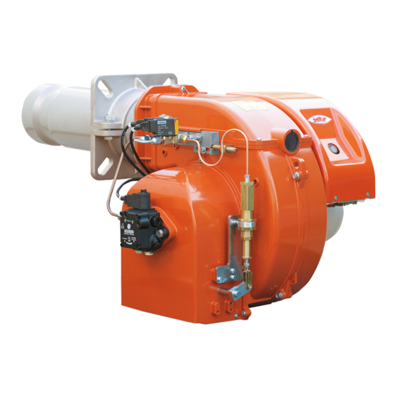
ITALIANO DESCRIZIONE TECNICA DEL BRUCIATORE DESIGNAZIONE BRUCIATORI asolIo Bruciatori di gasolio monostadio. BTL... • TBL... Bruciatori di gasolio bistadio. BTL...P • TBL... P • TBL...LX Bruciatori di gasolio a due stadi progressivi/modulante con camma meccanica. BT...DSPG TBL... ME Bruciatori di gasolio a due stadi progressivi/modulante con camma elettronica. N.B. -
Page 7: Dati Tecnici
ITALIANO DATI TECNICI MODELLO TBL 45P TBL 45P DACA TBL 60P TBL 60P DACA Portata minima Kg/h Portata massima Kg/h Potenza termica minima Potenza termica massima ³) emissioni mg/kWh Classe 1 Classe 1 Classe 1 Classe 1 Viscositá 1,5° E - 20° C 1,5°... -
Page 8: Caratteristiche Tecniche
• Controllo della presenza fiamma tramite sensore fiamma. CAMPO DI LAVORO mbar TBL 45P TBL 60P TBL 45P DACA TBL 60P DACA kg/h IMPORTANTE I campi di lavoro sono ottenuti su caldaie di prova rispondenti alla norma EN267 e sono orientativi per gli accoppiamenti bruciatore-caldaia. -
Page 9: Materiale A Corredo
ITALIANO MATERIALE A CORREDO MODELLO TBL 45P TBL 45P DACA TBL 60P TBL 60P DACA Guarnizione flangia attacco bruciatore N°4 - M12 N°4 - M12 N°4 - M12 N°4 - M12 Prigionieri N°4 - M12 N°4 - M12 N°4 - M12 N°4 - M12... -
Page 10: Descrizione Componenti
ITALIANO DESCRIZIONE COMPONENTI Testa di combustione Guarnizione Flangia attacco bruciatore Dispositivo regolazione testa Elettrovalvola 2° stadio Elettrovalvola di sicurezza Elettrovalvola 1° stadio Coperchio chiocciola Martinetto idraulico comando aria 9a Servomotore regolazione aria 10 Pompa combustibile liquido 11 Quadro elettrico pannello di comando 11a Quadro elettrico pannello di comando 12 Motore ventola 13 Targa identificazione bruciatore... -
Page 11: Quadro Elettrico
ITALIANO QUADRO ELETTRICO ersIone con martInetto IdraulIco Apparecchiatura Trasformatore d'accensione Contattore motore (Solo con alimentazione trifase) Relè termico (Solo con alimentazione trifase) Connettore 7 poli Connettore 4 poli Led bruciatore acceso Led bruciatore in blocco Pulsante di sblocco 10 Interruttore MARCIA / ARRESTO ersIone con servomotore elettrIco 0006081323_202404 9 / 52... -
Page 12: Dimensioni Di Ingombro
ITALIANO DIMENSIONI DI INGOMBRO Modello TBL 45P TBL 45P DACA TBL 60P TBL 60P DACA Modello E Ø F Ø TBL 45P 120 ÷ 350 TBL 45P DACA 120 ÷ 350 TBL 60P 140 ÷ 350 TBL 60P DACA 140 ÷ 350 Modello LØ... -
Page 13: Linea Di Alimentazione Combustibile
ITALIANO LINEA DI ALIMENTAZIONE COMBUSTIBILE IMPORTANTE Il circuito di alimentazione del combustibile deve essere realizzato in conformità alle norme di installazione e da personale abilitato. Il bruciatore è dotato di una pompa autoadescante in grado di aspirare il combustibile entro le lunghezze delle tubazioni indicate in tabella. IpI dI cIrcuIto dI alImentazIone del combustIbIle A) Impianto di alimentazione per gravità... - Page 14 ITALIANO ompa ausIlIarIa Se la distanza bruciatore-serbatoio supera le dimensioni (L) e/o l'al- tezza (H) indicate nel capitolo "Linea di alimentazione combustibile", prevedere un circuito di adduzione combustibile ad anello con pompa ausiliaria. ATTENZIONE Tutte le operazioni devono essere eseguite esclusivamente da personale qualificato.
-
Page 15: Pompa
Gasolio - HVO TBL 60P TBL 60P DACA ANV 77 12 bar G 1/8 G 1/8 G 1/8 Gasolio - HVO HVO: Olio Vegetale Idrotrattato. IMPORTANTE In caso di funzionamento con biofuel, contattare il Servizio Assistenza Tecnica Baltur. 0006081323_202404 13 / 52... -
Page 16: Apparecchiatura
ITALIANO APPARECCHIATURA • Rilevamento delle sottotensioni. • Pulsante di sblocco apparecchiatura con led multicolore (A). • Indicatore in vari colori dei messaggi delle condizioni di guasto ed operative. • Limitazione delle ripetizioni. • Funzionamento intermittente controllato massimo ogni 24 ore di funzionamento continuo (il dispositivo inizierà... - Page 17 ITALIANO chema dI collegamento Comando µC µC2 µC1 equenza A´ t1´ Messaggio di errore (allarme) Fusibile esterno Tempo di preventilazione BV... Valvola combustibile Termostato di Limiti / Pressostato Tempo di ventilazione EK1 Pulsante di sblocco Trasformatore dell’accensione Tempo pre-accensione EK2 Pulsante di sblocco remoto A-A' Inizio sequenza di avviamento bruciatore con Tempo di post-accensione preriscaldatore dell’olio (OH)
-
Page 18: Stato Di Funzionamento E Sblocco Apparecchiatura
ITALIANO STATO DI FUNZIONAMENTO E SBLOCCO APPARECCHIATURA L’apparecchiatura è dotata di segnalazione a 3 colori integrata nel pul- sante di sblocco (A). L’indicatore multicolore è il principale elemento per poter visualizzare, attivare e disattivare la diagnostica. blocco dell apparecchIatura Per effettuare lo sblocco dell’apparecchiatura premere per 1" il pulsan- te di sblocco presente nell’apparecchiatura (A) . - Page 19 ITALIANO ote prImo avvIo In seguito alla prima messa in funzione o a lavori di manutenzione, eseguire i seguenti controlli di sicurezza: Controlli di sicurezza Risultato atteso Blocco non modificabile al termine dell’intervallo di sicurezza Avvio del bruciatore con linea del rivelatore di fiamma precedentemente interrotta Funzionamento del bruciatore con simulazione di perdita della fiamma.
-
Page 20: Sensore Fiamma
ITALIANO SENSORE FIAMMA Il sensore fiamma è il rilevatore di presenza fiamma e deve quindi es- sere in grado di intervenire se, durante il funzionamento, la fiamma si spegne. In caso di spegnimento o assenza della fiamma, il rilevatore genera un blocco sull'apparecchiatura che comporta l'interruzione immediata del combustibile e l'arresto del bruciatore. -
Page 21: Installazione
• Verificare che l’impianto di smaltimento fumi NON sia ostruito. Modello LØ N Ø TBL 45P 200 ÷ 245 TBL 45P DACA 200 ÷ 245 TBL 60P 225 ÷ 300 TBL 60P DACA 225 ÷ 300 0006081323_202404... -
Page 22: Applicazione Del Bruciatore Alla Caldaia
Facendo riferimento alla quota D indicata in tabella, il range di penetra- TBL 45P 120 ÷ 350 zione della testa di combustione è 20-250 mm TBL 45P DACA 120 ÷ 350 X min (mm) = 120 - 100= 20 TBL 60P 140 ÷... - Page 23 ITALIANO ontaggIo gruppo testa • Adeguare la posizione della flangia di attacco (25) allentando le viti (6), la testa del bruciatore dovrà penetrare nel focolare della misura consigliata dal costruttore del generatore. • Posizionare sul canotto la guarnizione isolante (13) interponendo la corda (2) tra la flangia di attacco (25) e la guarnizione isolante (13).
-
Page 24: Conversione Bitubo-Monotubo
ITALIANO CONVERSIONE BITUBO-MONOTUBO Per convertire il circuito di alimentazione da bitubo a monotubo procedere come da schemi. ANV 77 • Togliere il tappo e la rondella del ritorno (1) e rimuove- re il grano by-pass. • Chiudere con rondella e tappo. ASV67A •... -
Page 25: Ugelli
ITALIANO UGELLI IMPORTANTE Le portate del 1° e del 2° stadio devono essere comprese tra i valori indicati nel capitolo "Campi di lavoro". Scegliere ugelli che rispettano i parametri indicati nelle tabelle. La portata massima del bruciatore è la somma delle portate dei due ugelli. - Page 26 ITALIANO abella portata ugellI Ugello Pressione Pompa bar Ugello G.P.H. G.P.H. 1,59 1,67 1,73 1,80 1,86 1,92 1,98 2,04 2,10 2,15 0,40 0,40 1,99 2,08 2,17 2,25 2,33 2,40 2,48 2,55 2,62 2,69 0,50 0,50 2,39 2,50 2,60 2,70 2,79 2,88 2,97 3,06...
-
Page 27: Posizione Disco - Elettrodi
PERICOLO / ATTENZIONE L'utilizzo di ugelli con angolo di polverizzazione a 45° è consigliato su camere di combustione strette. DANFOSS S 60° (TBL 45P). DANFOSS S 45° (TBL 60P) 1 - Diffusore 2 - Disco fiamma... -
Page 28: Collegamenti Elettrici
ITALIANO COLLEGAMENTI ELETTRICI cortocircuito "parziale" o un insufficiente isolamento tra linea e vvertenze sIcurezza elettrIca terra, la tensione sull'elettrodo di rivelazione può essere ridotta fino IMPORTANTE a provocare l'arresto di blocco dell'apparecchio, a causa dell'im- Il costruttore declina ogni responsabilità da modifiche o possibilità... - Page 29 ITALIANO cura dell Installatore • Installare un idoneo sezionatore per ciascuna linea di alimentazio- ne del bruciatore. • Il bruciatore può essere installato esclusivamente in sistemi TN oppure TT. Non può essere installato in sistemi isolati di tipo IT. • Per nessun motivo può essere abilitata la funzionalità di ripristino automatico (rimuovendo in modo irreversibile il relativo talloncino in plastica) sul dispositivo termico posto a protezione del motore ventola.
-
Page 30: Versione Con Martinetto
ITALIANO VERSIONE CON MARTINETTO • Per i modelli funzionanti con alimentazione monofase inserire i due connettori a 7 e 4 poli nelle apposite prese situate al di sotto della basetta di supporto quadro elettrico. • Nei modelli funzionanti con alimentazione trifase, per accedere ai componenti del quadro, svitare le due viti (6), arretrare leggermen- te il coperchio per sganciarlo dalla basetta di supporto. -
Page 31: Versione Con Dispositivo Automatico Chiusura Aria All'arresto (Daca)
ITALIANO VERSIONE CON DISPOSITIVO AUTOMATICO CHIUSURA ARIA ALL'ARRESTO (DACA) • Per accedere ai componenti del quadro, rimuovere il coperchio svitando le quattro viti (1). • Allentare le viti (6). Rimuovere la piastrina stringicavi (11), far passare attraverso il foro i due connettori a 7 e a 4 poli. •... -
Page 32: Sequenza Di Funzionamento
ITALIANO SEQUENZA DI FUNZIONAMENTO Chiudendo l’interruttore generale e l’interruttore ACCESO / SPENTO del quadro elettrico, se i termostati sono chiusi, la tensione raggiunge l’apparecchiatura di comando e controllo che inizia il suo funzionamen- Vengono così inseriti il motore ventola e il trasformatore di accensione. Il motore ventola mette in rotazione la ventola che effettua un lavaggio con aria della camera di combustione e contemporaneamente la pom- pa determina la circolazione del combustibile nei condotti, espellendo... -
Page 33: Accensione E Regolazione
ITALIANO ACCENSIONE E REGOLAZIONE AVVERTENZE PER L'AVVIAMENTO Indossare indumenti di protezione con pro- prietà elettrostatiche. ATTENZIONE La prima messa in funzione del bruciatore deve essere effettuata da personale abilitato come riportato nel presente manuale e in conformità alle norme e disposizioni di legge vigenti. PERICOLO / ATTENZIONE Le pompe che lavorano a 2800 giri non devono assolutamente lavorare a secco, perchè... -
Page 34: Regolazione Camme Servomotore
ITALIANO REGOLAZIONE CAMME SERVOMOTORE Il servomotore controlla l’albero a camme tramite il sistema di ingranaggi che attiva gli interruttori ausiliari e gli switch di finecorsa. L’indicatore di posizione (2) segna l’angolo di rotazione. Agire sulle camme per modificare la regolazione della potenza. Scala di riferimento Indicatore di posizione Perno inserzione ed esclusione accoppiamento motore - albero camme... -
Page 35: Regolazione Aria Sulla Testa Di Combustione
Modello Valore indice (15) flusso d’aria adeguato all’erogazione, con serranda aria in aspirazione 63 ÷ 40 0 ÷ 2,5 TBL 45P sensibilmente aperta. 84 ÷ 55 0 ÷ 3,3 TBL 60P Distanza testa-disco; regolare la distanza X seguendo le in- dicazioni: •... -
Page 36: Regolazione Prima Accensione Del Bruciatore
ITALIANO REGOLAZIONE PRIMA ACCENSIONE DEL BRUCIATORE • Evitare il funzionamento del secondo stadio. Posizionare l’inter- CAUTELA / AVVERTENZE ruttore del quadro elettrico in primo stadio. Se il bruciatore non è provvisto di interruttore primo e secondo stadio, togliere il collega- Con martinetto idraulico, mento del termostato per impedire l’inserzione del secondo stadio, Alla prima accensione del bruciatore possono verificarsi degli... -
Page 37: Martinetto Oscillante
ITALIANO MARTINETTO OSCILLANTE egolazIone posIzIone della serranda arIa prImo stadIo • Per aumentare la portata d’aria erogata, agire sulla ghiera (3) con rotazione antioraria, utilizzare la controchiave sul corpo (1) del martinetto. • Con questa manovra il corpo (1) si abbassa e favorisce l’apertura della serranda aria (9) per il primo stadio. -
Page 38: Primo Riempimento Circuito Idraulico
ITALIANO PRIMO RIEMPIMENTO CIRCUITO IDRAULICO Dopo aver controllato che i tappi di protezione in plastica posti dentro gli attacchi della pompa siano stati asportati, procedere come segue: • Portare nella posizione “O” l’interruttore posto sul bruciatore, evitando così l’inserzione automatica del bruciatore. on brucIatore monofase •... -
Page 39: Manutenzione
ITALIANO MANUTENZIONE AVVERTENZE PER LA MANUTENZIONE me vigenti, l’analisi dei gas di scarico della combustione verificando la correttezza dei valori di emissioni. • Pulire le serrande aria, il pressostato aria con presa di pressione Indossare indumenti di protezione con pro- ed il relativo tubo se presenti. - Page 40 ITALIANO Nel caso si renda necessaria la pulizia della testa di combustione, estrarne i componenti seguendo la procedura sotto indicata: • Scollegare i tubini gasolio (24) dai raccordi posti sotto il gruppo testa (attenzione al gocciolamento). IMPORTANTE Memorizzare la posizione delle tacche della piastrina mobile (23) rispetto al riferimento presente sulla chiocciola bruciatore.
-
Page 41: Tempi Di Manutenzione
ITALIANO TEMPI DI MANUTENZIONE Descrizione particolare Azione da eseguire Frequenza TESTA DI COMBUSTIONE CONTROLLO VISIVO, INTEGRITA' CERAMICHE, PULIZIA ESTREMITA', VERIFICA DISTANZA, ELETTRODI 1 ANNO VERIFICA CONNESSIONE ELETTRICA CONTROLLO VISIVO INTEGRITA', EVENTUALI DEFORMAZIONI, PULIZIA 1 ANNO DISCO FIAMMA COMPONENTI TESTA CONTROLLO VISIVO INTEGRITA', EVENTUALI DEFORMAZIONI, PULIZIA 1 ANNO COMBUSTIONE CONTROLLO VISIVO ED EVENTUALE SOSTITUZIONE... -
Page 42: Ciclo Di Vita
ITALIANO CICLO DI VITA La vita attesa dei bruciatori e dei relativi componenti dipende molto dal tipo di applicazione su cui il bruciatore è installato, dai cicli, dalla potenza erogata, dalle condizioni dell’ambiente in cui si trova, dalla frequenza e modalità di manutenzione, ecc. ecc. Le normative relative ai componenti di sicurezza prevedono una vita attesa di progetto espressa in cicli e/o anni di funzionamento. -
Page 43: Irregolarità Di Funzionamento - Cause - Rimedi
ITALIANO IRREGOLARITÀ DI FUNZIONAMENTO - CAUSE - RIMEDI Indossare indumenti di protezione con pro- prietà elettrostatiche. PERICOLO Quadro elettrico sotto tensione. Rischio elettrocuzione. In caso di blocco, premere il pulsante di sblocco (A). Se il blocco si ripete, procedere come segue: •... - Page 44 ITALIANO Indicazione ottica Descrizione Causa Rimedio Aprire alimentazione generale/ Assenza combustibile verificare pressione condotto combustibile Cavo elettrodo di accensione e/o sensore fiamma Verificare collegamenti scollegato Bruciatore in blocco durante la Verificare la posizione facendo riferimento Elettrodo di accensione in posizione errata fase di accensione per assenza 2 lampeggi al capitolo "...
-
Page 45: Irregolarità Di Funzionamento Apparecchiatura
ITALIANO IRREGOLARITÀ DI FUNZIONAMENTO APPARECCHIATURA In caso di blocco non modificabile, si disattivano le uscite delle valvole del combustibile, il motore del bruciatore e il dispositivo di accensione. In caso di irregolarità di funzionamento, l'apparecchiatura svolge le seguenti azioni: CAUSA RISPOSTA Interruzione dell’alimentazione Riavvio... - Page 46 ITALIANO IrregolarItÁ possIbIle causa rImedIo L'apparecchio va in "blocco" con la fiamma. Sensore fiamma interrotto o sporco di Pulire o sostituire. Il guasto è circoscritto al dispositivo di con- fumo. Controllare tutti i passaggi dei fumi trollo fiamma. Tiraggio insufficiente. nella caldaia e nel camino.
- Page 47 ITALIANO IrregolarItÁ possIbIle causa rImedIo Fiamma difettosa con presenza di faville. Pressione di polverizzazione troppo Ripristinarla al valore previsto. bassa. Diminuire l’aria comburente Eccesso di aria comburente. Pulire o sostituire. Ugello inefficiente perché sporco o Scaricare l'acqua dalla cisterna logoro. servendosi di una pompa adatta.
-
Page 48: Schemi Elettrici
ITALIANO SCHEMI ELETTRICI 46 / 52 0006081323_202404... - Page 49 ITALIANO 0006081323_202404 47 / 52...
- Page 50 ITALIANO TBL 35P TBL 45P 48 / 52 0006081323_202404...
- Page 51 ITALIANO 0006081323_202404 49 / 52...
- Page 52 ITALIANO 50 / 52 0006081323_202404...
- Page 53 ITALIANO APPARECCHIATURA L1 - L2- L3 Fasi SENSORE FIAMMA N - Neutro RELE’ TERMICO Terra SPIA BLOCCO ESTERNA Senza T2 SPIA DI FUNZIONAMENTO “SPIA FUNZIONAMENTO 2° STADIO“ SPIA DI BLOCCO CONTATTORE MOTORE VENTOLA CONTATTORE ESTERNO MOTORE VENTOLA CONTAORE INTERRUTTORE MARCIA ARRESTO PULSANTE SBLOCCO PULSANTE SBLOCCO LDU11 INTERRUTTORE GENERALE...
- Page 54 ITALIANO 52 / 52 0006081323_202404...
- Page 55 ENGLISH ENGLISH SUMMARY Warnings for use in safety conditions ........................2 Purpose of this manual ....................................2 Environmental conditions of operation, storage and transport ........................2 General warnings ......................................2 Residual risks ........................................3 Technical description of the burner ........................... 4 Burner designation ......................................4 Technical data ........................................5 Technical specifications ....................................6 Operating range ......................................6...
-
Page 56: Warnings For Use In Safety Conditions
• If the burner is to be used inside a system/process, please contact • Before starting to use the equipment, carefully read the "In- the sales offices Baltur. structions for use" in this manual and those directly applied • The equipment production date (month, year) is written on the to the product in order to minimize risks and accidents. -
Page 57: Residual Risks
Materials at high temperature. with it directly. Contact only qualified personnel. • Any product repairs must only be carried out by BALTUR authori- RISK OF ELECTROCUTION sed assistance centres or by its local distributor using only original spare parts. -
Page 58: Technical Description Of The Burner
ENGLISH TECHNICAL DESCRIPTION OF THE BURNER BURNER DESIGNATION Iesel Single-stage diesel burners. BTL... • TBL... Two-stage diesel burners. BTL...P • TBL... P • TBL...LX Progressive/modulating two-stage diesel burners with mechanical cam. BT...DSPG TBL... ME Progressive/modulating two-stage diesel burners with electronic cam. N.B. -
Page 59: Technical Data
ENGLISH TECHNICAL DATA MODEL TBL 45P TBL 45P DACA TBL 60P TBL 60P DACA Minimum flow rate Kg/h Maximum flow rate Kg/h Minimum thermal power Maximum thermal power ³) emissions mg/kWh Class 1 Class 1 Class 1 Class 1 Viscosity 1.5°... -
Page 60: Technical Specifications
• Flame presence control with flame sensor. OPERATING RANGE mbar TBL 45P TBL 60P TBL 45P DACA TBL 60P DACA kg/h IMPORTANT The operating ranges are obtained from test boilers corresponding to Standard EN267 and are indicative of the burner-boiler combination. -
Page 61: Standard Accessories
ENGLISH STANDARD ACCESSORIES MODEL TBL 45P TBL 45P DACA TBL 60P TBL 60P DACA Burner coupling flange gasket N°4 - M12 N°4 - M12 N°4 - M12 N°4 - M12 Stud bolts N°4 - M12 N°4 - M12 N°4 - M12 N°4 - M12... -
Page 62: Component Description
ENGLISH COMPONENT DESCRIPTION Combustion head Seal Burner connection flange Combustion head adjustment device 2nd stage solenoid valve Safety solenoid valve 1st stage solenoid valve Scroll cover Hydraulic air control jack 9a Air regulation servomotor 10 Liquid fuel pump 11 Control panel electrical switchboard 11a Control panel electrical switchboard 12 Fan motor 13 Burner identification plate... -
Page 63: Electrical Panel
ENGLISH ELECTRICAL PANEL ersIon wIth a hydraulIc jack Control box Ignition transformer Motor contactor (only with three-phase power supply) Thermal relay (only with three-phase power supply) 7-pole connector 4-pole connector Burner on LED Burner lock-out LED Unlock button 10 START/STOP switch ersIon wIth electrIc servomotor 0006081323_202404 9 / 52... -
Page 64: Overall Dimensions
ENGLISH OVERALL DIMENSIONS Model TBL 45P TBL 45P DACA TBL 60P TBL 60P DACA Model E Ø F Ø TBL 45P 120 ÷ 350 TBL 45P DACA 120 ÷ 350 TBL 60P 140 ÷ 350 TBL 60P DACA 140 ÷ 350 Model LØ... -
Page 65: Fuel Supply Line
ENGLISH FUEL SUPPLY LINE IMPORTANT The fuel supply circuit must be made in accordance with installation regulations and by qualified personnel. The burner is equipped with a self-priming pump capable of sucking fuel within the pipe lengths indicated in the table. uel supply cIrcuIt types A) Gravity feed system B) Gravity system with feed from the top of the tank... - Page 66 ENGLISH uxIlIary pump If the burner-tank distance exceeds the values (L) and/or the height (H) specified in chapter “Fuel supply line”, provide a loop fuel supply circuit with auxiliary pump. CAUTION All operations must be performed exclusively by qualified personnel. lock dIagram of hydraulIc cIrcuIt Foot valve Possible air regulation servomotor...
-
Page 67: Pump
Diesel - HVO TBL 60P TBL 60P DACA ANV 77 12 bar G 1/8 G 1/8 G 1/8 Diesel - HVO HVO: Hydrotreated Vegetable Oil. IMPORTANT In case of operation with biofuel, contact the Baltur Technical Service Department. 0006081323_202404 13 / 52... -
Page 68: Control Box
ENGLISH CONTROL BOX • Under-voltage detection. • Device release button with multi-coloured LED (A). • Indicator in various colours of fault and operational condition messages. • Limitation of repetitions. • Intermittent operation checked every 24 hours maximum of conti- nuous operation (the device will automatically initiate a controlled shutdown followed by a restart). - Page 69 ENGLISH onnectIon dIagram Comando µC µC2 µC1 equence A´ t1´ Error message (alarm) External fuse Preventilation time BV... Fuel valve Limit thermostat / Pressure switch Ventilation time EK1 Release button Ignition transformer Pre-ignition time EK2 Remote release button A-A' Burner start sequence with oil pre-heater After-ignition time (OH) Flame Signal...
-
Page 70: Operating Status And Equipment Resetting
ENGLISH OPERATING STATUS AND EQUIPMENT RESETTING The equipment is equipped with 3-colour signalling integrated in the reset button (A). The multi-coloured indicator is the main element for displaying, activa- ting and deactivating diagnostics. esettIng the equIpment To reset the equipment, press for 1" the reset button on equipment (A). The equipment is only reset if: •... - Page 71 ENGLISH emarks regardIng fIrst IgnItIon After first ignition or after any maintenance work, carry out the following safety checks: Safety checks Expected result Lock-out cannot be modified at the end of the safety time Burner start with previously interrupted flame detector line Lock-out cannot be modified Burner operation with flame loss simulation.
-
Page 72: Flame Sensor
ENGLISH FLAME SENSOR The flame sensor is the device detecting the flame and therefore must be able to intervene if the flame turns off during operation. In case of flame extinction or failure, the detector locks out the equip- ment, which results in the fuel being immediately cut off and the burner stopped. -
Page 73: Installation
• Check that the fume disposal system is NOT obstructed. Model LØ N Ø TBL 45P 200 ÷ 245 TBL 45P DACA 200 ÷ 245 TBL 60P 225 ÷ 300 TBL 60P DACA 225 ÷ 300 0006081323_202404 19 / 52... -
Page 74: Burner Connection To The Boiler
Model the combustion head is 20-250 mm TBL 45P 120 ÷ 350 X min (mm) = 120 - 100= 20 TBL 45P DACA 120 ÷ 350 X max (mm) = 350 - 100= 250 TBL 60P 140 ÷ 350 TBL 60P DACA 140 ÷... - Page 75 ENGLISH ead unIt assembly • Adjust the position of the coupling flange (25) by loosening the screws (6) so that the burner head enters the furnace to the extent recommended by the generator manufacturer. • Position the insulating gasket (13) on the sleeve, by inserting the cord (2) between the coupling flange (25) and the insulating gasket (13).
-
Page 76: Two-Pipe/One-Pipe Conversion
ENGLISH TWO-PIPE/ONE-PIPE CONVERSION To convert the supply circuit from two-pipe to one-pipe, proceed as shown in the diagrams. ANV 77 • Remove the cap and the return washer (1) and remove the by-pass screw. • Close with washer and cap. ASV67A •... -
Page 77: Nozzles
ENGLISH NOZZLES IMPORTANT The 1st and 2nd stage flow rates must range between the values indicated in chapter “Working ranges”. Choose nozzles that comply with the parameters specified in the tables. The maximum capacity of the burner is the sum of the capacities of the two nozzles. - Page 78 ENGLISH ozzle flow rate table Nozzle Pump pressure in bar Nozzle G.P.H. G.P.H. 1,59 1,67 1,73 1,80 1,86 1,92 1,98 2,04 2,10 2,15 0,40 0,40 1,99 2,08 2,17 2,25 2,33 2,40 2,48 2,55 2,62 2,69 0,50 0,50 2,39 2,50 2,60 2,70 2,79 2,88...
-
Page 79: Electrode - Disk Position
DANGER / ATTENTION For narrow combustion chambers, it is recommended to use nozzles with a 45° atomisation angle. DANFOSS S 60° (TBL 45P). DANFOSS S 45° (TBL 60P) 1 - Diffuser 2 - Flame disc 3 - Nozzle holder sleeve... -
Page 80: Electrical Connections
ENGLISH ELECTRICAL CONNECTIONS than 2 m and insulating voltage > 25 kV); lectrIc safety warnIngs • The power lines must be distanced from the hot parts. IMPORTANT • The burner can be installed exclusively in environments with pollu- The manufacturer shall not be liable for changes or connections tion degree 2 as specified in Standard EN 60204-1. - Page 81 ENGLISH o be carrIed out by the Installer • Install a suitable disconnecting switch for each burner supply line. • The burner can be installed only in TN or TT systems. It cannot be installed in isolated system of IT type. •...
-
Page 82: Version With Hydraulic Jack
ENGLISH VERSION WITH HYDRAULIC JACK • For the models with single-phase power supply, insert the two 7- and 4-pole connectors into the appropriate sockets located below the electrical switchboard support base. • For the models with three-phase power supply, in order to access the panel components, unscrew the 2 screws (6) and pull back slightly the cover to detach it from the electrical panel base. -
Page 83: Version With Automatic Air Closure Device At Stop (Daca)
ENGLISH VERSION WITH AUTOMATIC AIR CLOSURE DEVICE AT STOP (DACA) • To access the panel components, remove the cover by undoing the four screws (1). • Loosen the screws (6). Remove the cable retaining plate (11), pass the two 7- and 4-pole connectors through the hole. •... -
Page 84: Operation Sequence
ENGLISH OPERATION SEQUENCE Closing the main switch and the ON / OFF switch of the electric panel, if the thermostats are closed, the voltage reaches the command and control equipment which starts operating. This switches on the fan motor and the ignition transformer. The fan motor starts fan rotation, which performs a wash with air in the combustion chamber and, at the same time, the pump makes the fuel circulate in the pipes, expelling any air bubbles through the return line. -
Page 85: Starting Up And Regulation
ENGLISH STARTING UP AND REGULATION START-UP WARNING NOTES Wear protective clothing with electrostatic properties. CAUTION The burner initial start-up must be carried out by authorised personnel as stated in this manual and in accordance with current standards and legal regulations. DANGER / ATTENTION Pump operating at 2800 r.p.m. -
Page 86: Servomotor Cam Regulation
ENGLISH SERVOMOTOR CAM REGULATION The servomotor controls the camshaft via the gear system, which activates the auxiliary and limit switches. The (2) position indicator marks the angle of rotation. Act on the cams to change the power setting. Reference scale Position indicator Motor-camshaft coupling On/Off pin Adjustable camshaft... -
Page 87: Air Regulation On The Combustion Head
Model Index value (15) table for the supply with the air damper considerably open. 63 ÷ 40 0 ÷ 2,5 TBL 45P 84 ÷ 55 0 ÷ 3,3 TBL 60P Head-disk distance; adjust distance X following the in- structions: •... -
Page 88: Adjustment Before Switching On The Burner
ENGLISH ADJUSTMENT BEFORE SWITCHING ON THE BURNER • Avoid second stage operation. Set the switch on the electrical CAUTION / WARNINGS panel to the first stage position. If the burner does not have the first and second stage switch, disconnect the thermostat to avoid With a hydraulic jack, activating the second stage, if installed. -
Page 89: Oscillating Jack
ENGLISH OSCILLATING JACK djustment of fIrst stage aIr dumper posItIon • To increase the flow rate, turn ring nut (3) anticlockwise using the counter wrench on the body (1) of the jack. • This operation lowers the body (1) and favours the opening of the first stage air damper (9). -
Page 90: First Hydraulic Circuit Filling
ENGLISH FIRST HYDRAULIC CIRCUIT FILLING After checking that the protective plastic caps inside the pump fittings have been removed, proceed as follows: • Set the burner switch on “O” to prevent an automatic activation of the burner. Ith a sIngle phase burner •... -
Page 91: Maintenance
ENGLISH MAINTENANCE SERVICING RECOMMENDATIONS condition, have not been deformed and are free from impurities or deposits deriving from the installation environment and/or from combustion. Wear protective clothing with electrostatic • Analyse combustion gases and check emissions values. properties. • Check the integrity and cleanliness of the nozzles.In case of repla- cement, carry out a combustion check. - Page 92 ENGLISH If the combustion head needs to be cleaned, remove the components following the procedure indicated below: • Disconnect the diesel hoses (24) from the connectors beneath the head unit (mind the dripping). IMPORTANT Store in memory the exact position of the mobile plate marks (23) with respect to the reference on the burner scroll.
-
Page 93: Maintenance Time
ENGLISH MAINTENANCE TIME Part description Action to be performed Frequency COMBUSTION HEAD VISUAL CHECK, CERAMIC PARTS INTEGRITY, EDGES CLEANING, DISTANCE CHECK, ELECTRI- ELECTRODES 1 YEAR CAL CONNECTION CHECK INTEGRITY VISUAL CHECK FOR ANY DEFORMATIONS, CLEANING 1 YEAR FLAME DISC COMBUSTION HEAD INTEGRITY VISUAL CHECK FOR ANY DEFORMATIONS, CLEANING 1 YEAR COMPONENTS... -
Page 94: Life Cycle
ENGLISH LIFE CYCLE The expected lifespan of burners and relevant components depends very much from the type of application on which the burner is installed, from cycles ,of delivered power, from the conditions of the environment in which it is located, from maintenance frequency and mode, etc. Standards about safety components provide for a project expected lifespan expressed in cycles and/or years of operation. -
Page 95: Operating Faults - Causes- Solutions
ENGLISH OPERATING FAULTS - CAUSES- SOLUTIONS Wear protective clothing with electrostatic properties. DANGER Powered electric panel. Risk of electrocution. In case of lock-out, hold down the lockout reset button (A). If the lock-out occurs again, proceed as follows: • Check the number of flashes on the equipment. To activate the diagnosis phase (red light blinking fast) press the button for more than 3 seconds. - Page 96 ENGLISH Visual indication Description Cause Solution Open the general supply/ No fuel check the fuel line pressure Ignition electrode cable and/or flame sensor discon- Check connections nected Check the position by referring to the Burner in lockout during ignition Ignition electrode in the wrong position 2 blinks chapter “Disc-electrode position”...
-
Page 97: Equipment Operating Problems
ENGLISH EQUIPMENT OPERATING PROBLEMS In case of a lockout that cannot be changed, the fuel valve outputs, burner motor and ignition device are switched off. In case of a malfunction, the equipment performs the following actions: CAUSE RESPONSE Power supply interruption Restart Voltage below the minimum voltage threshold (AC 165 V) Safety switching off... - Page 98 ENGLISH IrregularIty possIble cause remedy The equipment locks out with the flame on. Flame sensor off or soiled with smoke Clean or replace. The fault is limited to the flame control de- Insufficient draught. Check all the smoke ducts in the vice.
- Page 99 ENGLISH IrregularIty possIble cause remedy Defective flame with sparks. Spraying pressure is too low. Restore it at the required value. Too much combustion air. Reduce combustion air Nozzle inefficient because dirty or Clean or replace. worn. Drain water from the tank using a Water in the fuel.
-
Page 100: Wiring Diagrams
ENGLISH WIRING DIAGRAMS 46 / 52 0006081323_202404... - Page 101 ENGLISH 0006081323_202404 47 / 52...
- Page 102 ENGLISH TBL 35P TBL 45P 48 / 52 0006081323_202404...
- Page 103 ENGLISH 0006081323_202404 49 / 52...
- Page 104 ENGLISH 50 / 52 0006081323_202404...
- Page 105 ENGLISH CONTROL BOX L1 - L2- L3 Phases Flame sensor N - Neutral THERMAL RELAY Ground EXTERNAL LOCK INDICATOR LIGHT Without T2 OPERATION INDICATOR LIGHT “2ND STAGE OPERATION LIGHT“ LOCK-OUT WARNING LIGHT FAN MOTOR CONTACTOR EXTERNAL CONTACTOR FAN MOTOR HOUR METER START/STOP SWITCH RELEASE BUTTON LDU11 RELEASE BUTTON...
- Page 106 ENGLISH 52 / 52 0006081323_202404...
- Page 108 44042 Cento (Fe) - Italy info@baltur.it Baltur si riserva ogni possibilità di modifica dei dati tecnici e di quant'altro riportato nel presente manuale. Baltur reserves the right to modify the technical data and anything else reported in this manual.
Need help?
Do you have a question about the TBL 45P and is the answer not in the manual?
Questions and answers