
Related Manuals for Matrox Radient eCL Series


Summary of Contents for Matrox Radient eCL Series
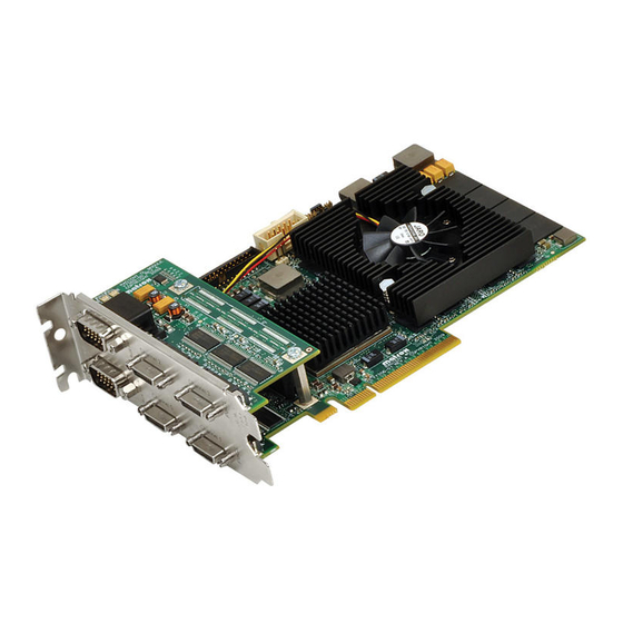
- Page 1 Matrox Radient eCL Installation and Hardware Reference Manual no. Y11144-101-0200 February 5, 2014...
- Page 2 © Copyright Matrox Electronic Systems Ltd., 2010-2014. All rights reserved. Limitation of Liabilities: In no event will Matrox or its suppliers be liable for any indirect, special, incidental, economic, cover or consequential damages arising out of the use of or inability to use the product, user documentation or related...
-
Page 3: Table Of Contents
Chapter 2: Hardware installation ......19 Installing your Matrox Radient eCL board ....... . 20 Installing the cable adapter bracket . - Page 4 Matrox Radient eCL hardware reference ........32...
- Page 5 Dimensions and environmental specifications ......72 Connectors on Matrox Radient eCL boards ....... 73 Camera Link video input connectors.
-
Page 7: Chapter 1: Introduction
Chapter Introduction Chapter 1: This chapter briefly describes the features of the Matrox Radient eCL boards, as well as the software that can be used with the boards. -
Page 8: Matrox Radient Ecl Boards
Matrox Radient eCL supports power-over Camera Link (PoCL) compliant video sources and Camera Link frequencies of 20 MHz to 85 MHz. This manual uses the term Matrox Radient eCL to refer to all members of Matrox Radient eCL. It uses the term Matrox Radient eCL-DB/QB to refer to both Matrox Radient eCL-DB and eCL-QB. - Page 9 Note that, without the expansion module, this is a flow diagram of Matrox Radient eCL-DB. Host x8 PCIe bus With the expansion module, this is a flow diagram of Matrox Radient eCL-QB. eCL-DB is not upgradable to eCL-QB; the eCL-DB does not have the required connector for the eCL-QB module.
- Page 10 2 GB/s 2 GB/s Opto Aux In (2) Note that, without the expansion module, this is a flow diagram of Matrox Radient eCL-SF. Host x8 PCIe bus With the expansion module, this is a flow diagram of Matrox Radient eCL- DF.
-
Page 11: General Acquisition Features
FPGA configuration can be rearranged to perform the operations in the required sequence, without having to necessarily generate a new FPGA configuration. When the need arises, Matrox’s FPGA design services can be employed to generate an application-specific FPGA configuration. Before the Processing FPGA can process grabbed images, they must be stored in main on-board memory. -
Page 12: Additional Functionality
Processing FPGA performs operation. As Processing FPGA memory, Matrox Radient eCL uses 4 banks of QDR-II SRAM that total 16 or 32 Mbytes of memory and have a total transfer rate of up to 4.0 Gbytes/sec in each direction. -
Page 13: Data Transfer
Host memory (frame start address and line pitch). Software To operate Matrox Radient eCL, you can use one or more Matrox Imaging software products that supports the board. These are the Matrox Imaging Library (MIL) and its derivatives (for example, MIL-Lite and Matrox Intellicam). -
Page 14: Essentials To Get Started
• MIL or one of its derivatives. This software should be installed after you install your board. *. Note that you can also install Matrox Radient eCL in a x4 PCIe slot that has a mechanical x8 connector; however, the maximum transfer rate between Matrox Radi-... -
Page 15: Inspecting The Matrox Radient Ecl Package
Consult your software package for other computer requirements (for example, operating system and memory requirements). Inspecting the Matrox Radient eCL package You should check the contents of your Matrox Radient eCL package when you first open it. If something is missing or damaged, contact your Matrox representative. -
Page 16: Available Separately
Available separately You might have also ordered one or more of the following: • MIL or MIL-Lite. Matrox Intellicam is included with both of these software packages. ❖ If needed, you can purchase a 26-pin high-density male mini Camera Link or PoCL-compliant Camera Link cable (HDR or SDR) from the video source manufacturer, Components Express inc., 3M Interconnect Solutions for Factory... - Page 17 To do so, you should first complete and submit the online Technical Support Request Form, accessible from the above-mentioned page. Once the information is submitted, a Matrox support agent will contact you shortly thereafter by email or phone, depending...
- Page 18 18 Chapter 1: Introduction...
-
Page 19: Chapter 2: Hardware Installation
Chapter Hardware Chapter 2: installation This chapter explains how to install your Matrox Radient eCL board in your computer. -
Page 20: Installing Your Matrox Radient Ecl Board
PCIe 64-bit PCI-X slot *. Note that you can also install Matrox Radient eCL in a x4 PCIe slot that has a mechanical x8 connector; however, the maximum transfer rate between Matrox Radi- ent eCL and the Host is reduced by 50%. - Page 21 Installing your Matrox Radient eCL board Matrox Radient eCL might drop frames if there are not at least 8 active lanes on the PCIe connector to the Host (for example, if the board is connected to a x8 PCIe connector that has only four active lanes ).
- Page 22 4. Position your Matrox Radient eCL board in the selected slot(s), and then press the board firmly but carefully into the connector of the slot.
- Page 23 5. Anchor the board using the screw that you removed in step 3. 6. If required, install the cable adapter bracket of your Matrox Radient eCL board, as described in the section Installing the cable adapter bracket, later in this chapter.
-
Page 24: Installing The Cable Adapter Bracket
Matrox Radient eCL board. To do so, position the cable so that the black wire is on the same side as the bracket of the Matrox Radient eCL board. 3. Slide the bracket into the opening at the back of the selected slot. -
Page 25: Connecting Video Sources
Connecting video sources Connecting video sources The Matrox Radient eCL board has the following connectors on its bracket(s): • Two or four Camera Link-compliant video input connectors. Used to receive video input, timing, and synchronization signals, from the video source. These are also used to transmit/receive communication signals between the video source and the frame grabber. - Page 26 26 Chapter 2: Hardware installation Attach video sources to Matrox Radient eCL as follows: M a t r o x C a m e r a L i n k C a m e r a L i n k...
- Page 27 SDR) at one end. When connecting to PoCL-compliant video sources, you should use PoCL-compliant Camera Link cables (HDR or SDR). Camera Link cables are not available from Matrox; for possible sources, see the Connectors on Matrox Radient eCL boards section in Appendix B: Technical information.
- Page 28 28 Chapter 2: Hardware installation...
-
Page 29: Chapter 3: Using Multiple Matrox Radient Ecl Boards
Chapter Using multiple Chapter 3: Matrox Radient eCL boards This chapter explains how to use multiple Matrox Radient eCL boards. -
Page 30: Installation Of Multiple Boards
30 Chapter 3: Using multiple Matrox Radient eCL boards Installation of multiple boards You can install and use multiple Matrox Radient eCL boards in one computer. Install each additional Matrox Radient eCL board as you installed the first board (refer to Chapter 2: Hardware installation). The number of Matrox Radient eCL boards that you can install is primarily dependent on the number of physical slots in your computer and your BIOS;... -
Page 31: Chapter 4: Matrox Radient Ecl Hardware Reference
Chapter Matrox Radient eCL Chapter 4: hardware reference This chapter explains the architecture, features, and modes of the Matrox Radient eCL hardware. -
Page 32: Matrox Radient Ecl Hardware Reference
Matrox Radient eCL hardware related to the processing and transfer of data. A summary of the features of Matrox Radient eCL, as well as pin assignments for the various connectors, can be found in Appendix B: Technical information. - Page 33 Note that, without the expansion module, this is a flow diagram of Matrox Radient eCL-DB. Host x8 PCIe bus With the expansion module, this is a flow diagram of Matrox Radient eCL-QB. eCL-DB is not upgradable to eCL-QB; the eCL-DB does not have the required connector for the eCL-QB module.
- Page 34 2 GB/s 2 GB/s eCL-SF/DF Opto Aux In (2) Note that, without the expansion module, this is a flow diagram of Matrox Radient eCL-SF. Host x8 PCIe bus With the expansion module, this is a flow diagram of Matrox Radient eCL- DF.
-
Page 35: Matrox Radient Ecl Acquisition Section
Matrox Radient eCL acquisition section Matrox Radient eCL acquisition section Matrox Radient eCL can capture video from digital video sources compliant with the Camera Link specification. Matrox Radient eCL can provide power over Camera Link to attached video sources. Matrox Radient eCL supports monochrome, RGB color, and Bayer color-encoded acquisition. -
Page 36: Performance
; t h i s m i g h t c a u s e y o u t o m i s s f r a m e s . The maximum pixel clock frequency is dependent on the length of the cable used. Refer to the Technical features of Matrox Radient eCL subsection of the Board summary section in Appendix B: Technical information. -
Page 37: Supported Video Sources
Matrox Radient eCL acquisition section Supported video sources Each acquisition path supports the following video sources: V i d e o s o u r c e s s u p p o r t e d p e r a c q u i s i t i o n p a t h C a m e r a L i n k S t a n d a r d •... -
Page 38: Channellink Receivers
Radient eCL-SF has three ChannelLink receivers that can only operate synchronously. In single-Medium mode, Matrox Radient eCL-SF only uses two of the receivers, whereas in single-Full mode, it uses all three receivers. Matrox Radient eCL-DF has an additional three ChannelLink receivers that operate in the same manner as those on eCL-SF, permitting eCL-DF to operate in dual-Medium or dual-Full mode. -
Page 39: Demultiplexers To Support Time-Multiplexed Video Sources
UARTs For each acquisition path, Matrox Radient eCL offers an LVDS-compatible Matrox serial interface. Each interface is mapped as a COM port so that it can be accessed through the Win32 API. Each interface is comprised of both a transmit port and a receive port, permitting the interface to work in full-duplex (bidirectional) mode. -
Page 40: Psgs
40 Chapter 4: Matrox Radient eCL hardware reference PSGs For each acquisition path, Matrox Radient eCL features a programmable synchronization generator (PSGs). Each PSG allows for independent acquisition from one video source, since each PSG is responsible for managing all video timing and synchronization signals. -
Page 41: Camera Control And Auxiliary Signals For Matrox Radient Ecl-Db And Ecl-Qb
Camera control and auxiliary signals for Matrox Radient eCL-DB and eCL-QB The following tables summarize the auxiliary functionality that the PSGs support, and the corresponding signals that the PSGs can receive/generate, for Matrox Radient eCL-DB and eCL-QB. The table also documents the MIL constants to use. - Page 42 42 Chapter 4: Matrox Radient eCL hardware reference T T L A u x I / O O P T O A u x I n L V D S A u x I n L V D S A u x O u t...
- Page 43 Matrox Radient eCL acquisition section L V D S c a m . c t r l C L c o n n e c t . 0 C L c o n n e c t . 1 C L c o n n e c t . 2 C L c o n n e c t .
- Page 44 44 Chapter 4: Matrox Radient eCL hardware reference L V D S c a m . c t r l T T L A u x I / O L V D S A u x O u t C a m e r a L i n k...
-
Page 45: Camera Control And Auxiliary Signals For Matrox Radient Ecl-Sf And Ecl-Df
The following tables summarize the auxiliary functionality that the PSGs support, and the corresponding signals that the PSGs can receive/generate, for Matrox Radient eCL-SF and eCL-DF. The table also documents the MIL constants to use. L V D S c a m . c t r l L V D S c a m . - Page 46 46 Chapter 4: Matrox Radient eCL hardware reference T T L A u x I / O O P T O A u x I n L V D S A u x I n L V D S A u x O u t...
- Page 47 Matrox Radient eCL acquisition section L V D S c a m . c t r l C L c o n n e c t . 0 C L c o n n e c t . 2 t i o...
- Page 48 48 Chapter 4: Matrox Radient eCL hardware reference L V D S c a m . c t r l T T L A u x I / O L V D S A u x O u t C a m e r a L i n k...
-
Page 49: Specifications Of The Auxiliary And Camera Control Signals
You can set the direction of a bidirectional auxiliary I/O signal using the MIL-Lite function MdigControl() with M_IO_MODE. You specify the purpose of the camera control and auxiliary signals in the DCF with Matrox Intellicam. You can then program these signals using the MIL-Lite function MdigControl() with M_IO... , M_TRIGGER..., M_TIMER... -
Page 50: Timers
50 Chapter 4: Matrox Radient eCL hardware reference Timers Each PSG has two timers. These timers can each generate a timer output signal which allows you to control the exposure time and other external events related to the video source (such as a strobe). The timer signals can be output using camera control signals or auxiliary output signals (or auxiliary I/O signals in output mode). -
Page 51: Trigger
Matrox Radient eCL acquisition section Trigger Each PSG has 4 trigger controllers. Each trigger controller can trigger the image acquisition, the timers, and/or the synchronization signals of the PSG’s acquisition path. Only one auxiliary signal per trigger controller can be programmed as a trigger input signal. -
Page 52: Synchronization
The board can also receive a dedicated clock signal. Rotary decoder The PSGs of the Matrox Radient eCL board feature a rotary decoder (quadrature decoder). A rotary decoder is used to decode quadrature input received from a rotary encoder with quadrature output. -
Page 53: User Signals
Matrox Radient eCL acquisition section The rotary decoder supports a maximum encoder frequency equal to 1/3 of the pixel clock frequency of the video source. The LVDS receivers of the Matrox Radient eCL board support 5 V rotary encoders. Note that an external source must be used to power the rotary encoder (for ❖... -
Page 54: Acquisition Controller
On Matrox Radient eCL-DB/QB, the acquisition controller can write to four non-sequential memory regions (zones) per acquisition path. On Matrox Radient eCL-SF/DF, the acquisition controller can typically write to eight non-sequential memory regions in single-Medium or single-Full mode, per acquisition path. -
Page 55: Processing Fpga
Processing FPGA To reduce the number of image processing tasks that the Host CPU must perform, Matrox Radient eCL has a Processing FPGA. The Processing FPGA can be configured to offload and even accelerate the most compute-intensive part of typical image processing applications, without generating additional data traffic within the host computer (Host). -
Page 56: Fpga Chip
56 Chapter 4: Matrox Radient eCL hardware reference FPGA chip The Processing FPGA on Matrox Radient eCL is implemented using a highly customizable, Altera Stratix III or IV FPGA, with core clock of up to 133 MHz. Depending on your application requirements, you can purchase the board with one of the following six supported FPGA chips. -
Page 57: Host Interface
Matrox Radient eCL uses PCIe technology to communicate with the Host. Under optimum conditions, Matrox Radient eCL can exchange data with the Host at a peak transfer rate of up to 2 Gbytes/sec, but can sustain a transfer rate of up to 1750 Mbytes/sec. -
Page 58: Color Space Converter And Pixel Formatter
58 Chapter 4: Matrox Radient eCL hardware reference Color space converter and pixel formatter The color space converter and pixel formatter can convert data being transferred off-board as follows: • Resizing. Image data can be cropped (ROI capture) and/or subsampled. This can be useful to implement custom software-based motion detection because at a reduced scale, image comparison is faster. - Page 59 Host interface When you grab into a Host buffer (for example, using the MIL-Lite function Formatting/ converting data MdigGrab()), use MdigControl() with M_SOURCE_OFFSET_X/Y, when grabbing into M_SOURCE_SIZE_X/Y, and/or M_GRAB_SCALE_X/Y to crop or resize Host buffers image data when grabbing. The color space converter and pixel formatter are not used to flip images grabbed into Host buffers;...
- Page 60 60 Chapter 4: Matrox Radient eCL hardware reference...
-
Page 61: Appendix A: Glossary
Appendix A: Glossary Appendix A: This appendix defines some of the specialized terms used in the Matrox Radient eCL documentation. -
Page 62: Glossary
62 Appendix A: Glossary Glossary • Bandwidth A term describing the capacity to transfer data. Greater bandwidth is needed to sustain a higher transfer rate. Greater bandwidth can be achieved, for example, by using a wider bus or by increasing the clock frequency at which an interface or a core operates (for example, increasing the DDR2 SDRAM clock frequency). - Page 63 Double Data Rate2 Synchronous Dynamic Random Access Memory. A type of memory used for image capture and processing. SDRAM allows Matrox Radient eCL to access data at a very high speed, which is important for I/O-bound functions. This type of memory allows for very high density at low prices, and is very efficient as long as the data is accessed contiguously.
- Page 64 64 Appendix A: Glossary • Grab To acquire an image from a video source. • Horizontal blanking period The portion of a video signal after the end of a line and before the beginning of a new line. During this period, the video signal is "blank". See also vertical blanking period.
- Page 65 Static Random Access Memory Quad Data Rate II. A type of memory used for processing. SRAM allows Matrox Radient eCL to access data at a very high speed, in a random or contiguous manner. The memory interface is actually double data-rate, but is tagged quad data-rate because it has independent read and write ports.
- Page 66 66 Appendix A: Glossary...
-
Page 67: Appendix B: Technical Information
Appendix B: Technical Appendix B: information This appendix contains information that might be useful when installing your Matrox Radient eCL board. -
Page 68: Board Summary
(EP3SL150, EP3SL200, EP3SL340, EP3SE110, or EP3SE260) or an Altera Stratix IV FPGA (EP4SE530 or EP4SE820). *. Note that you can also install Matrox Radient eCL in a x4 PCIe slot that has a mechanical x8 connector; however, the maximum transfer rate between Matrox Radi-... - Page 69 Board summary • Has a x8 PCIe GEN 1 Host interface. • Can provide power over Camera Link (PoCL) with SafePower. The PoCL protection on-board fuse can sustain a current of 0.4 A. • Supports a maximum clock frequency of up to 85 MHz. Clock frequency is also dependent on the length of the cable used.
- Page 70 - Two opto-isolated auxiliary input signals (trigger input or user input) per acquisition path. *. See the Camera control and auxiliary signals for Matrox Radient eCL-DB and eCL-QB and Camera control and auxiliary signals for Matrox Radient eCL-SF and eCL-DF sec- tions in Chapter 4: Matrox Radient eCL hardware reference chapter for supported func- tionality.
-
Page 71: Electrical Specifications
Electrical specifications Electrical specifications M a t r o x R a d i e n t e C L ( s t a r t i n g f r o m v e r s i o n 0 0 2 ) O p e r a t i n g v o l t a g e a n d T y p i c a l : 3 . -
Page 72: Dimensions And Environmental Specifications
72 Appendix B: Technical information Dimensions and environmental specifications The following dimensions and environmental specifications apply to both Matrox Radient eCL-DB/QB and eCL-SF/DF: • Dimensions of Matrox Radient eCL-DB and eCL-SF: 16.76 L x 11.12 H x 1.871 W cm (6.6" x 4.376" x 0.737") from bottom edge of goldfinger to top edge of board. -
Page 73: Connectors On Matrox Radient Ecl Boards
Connectors on Matrox Radient eCL boards On the Matrox Radient eCL boards, there are several interface connectors. On the bracket of Matrox Radient eCL-DB and eCL-SF, there are two Camera Link video input connectors and an auxiliary I/O connector. On the double bracket of Matrox Radient eCL-QB and eCL-DF, there are two pairs of Camera Link video input connectors and two auxiliary I/O connectors. -
Page 74: Camera Link Video Input Connectors
The number of Camera Link video input connectors and their pinout depends on the version of Matrox Radient eCL and the configuration. The pinout of these connectors follows the Camera Link standard. On Matrox Radient eCL-DB, there are two Camera Link connectors; whereas on... - Page 75 Camera control and auxiliary signals Chapter 4: Matrox Radient eCL hardware reference † . S e e t h e t a b l e i n t h e s e c t i o n o f f o r m o r e i n f o r m a t i o n o n w h i c h a u x i l i a r y i n p u t s i g n a l s ( o r a u x i l i a r y I / O s i g n a l s s e t t o i n p u t ) c a n b e r e r o u t e d o n t o t h e c a m e r a c o n t r o l o u t p u t s i g n a l s .
- Page 76 Matrox Radient eCL-SF and eCL-DF whereas on Matrox Radient eCL-DF, there are two pairs (0-1 and 2-3) of Camera Link connectors. To each pair of connectors, you can connect one video source in Medium or Full configuration. Each of the connector pairs uses a single acquisition path.
-
Page 77: External Auxiliary I/O Connectors
You can purchase such a cable from your video source manufacturer, Components Express inc., 3M Interconnect Solutions for Factory Automation, Intercon 1, or other third parties. Note that this cable is not available from Matrox. ❖ If using both Camera Link connectors to connect to the same video source (Medium configuration or Full configuration), the cables you choose must be of the same type and length. - Page 78 78 Appendix B: Technical information Pinouts for auxiliary I/O connectors of Matrox Radient eCL-DB and eCL-QB The pinout for auxiliary I/O connector A is as follows for Matrox Radient eCL-DB and eCL-QB. M I L c o n s t a n t...
- Page 79 Connectors on Matrox Radient eCL boards The pinout for auxiliary I/O connector B is as follows for Matrox Radient eCL-QB. M I L c o n s t a n t D i g i t i z e r...
- Page 80 80 Appendix B: Technical information The pinout for auxiliary I/O connector C is as follows for Matrox Radient eCL-DB and eCL-QB. M I L c o n s t a n t D i g i t i z e r...
- Page 81 Connectors on Matrox Radient eCL boards The pinout for auxiliary I/O connector D is as follows for Matrox Radient eCL-QB. M I L c o n s t a n t D i g i t i z e r...
- Page 82 82 Appendix B: Technical information Pinouts for auxiliary I/O connectors of Matrox Radient eCL-SF and eCL-DF The pinout for auxiliary I/O connector A is as follows for Matrox Radient eCL-SF and eCL-DF. M I L c o n s t a n t...
- Page 83 Connectors on Matrox Radient eCL boards The pinout for auxiliary I/O connector B is as follows for Matrox Radient eCL-DF. M I L c o n s t a n t D i g i t i z e r...
- Page 84 84 Appendix B: Technical information The pinout for auxiliary I/O connector C is as follows for Matrox Radient eCL-SF and eCL-DF M I L c o n s t a n t D i g i t i z e r...
- Page 85 Connectors on Matrox Radient eCL boards The pinout for auxiliary I/O connector D is as follows for Matrox Radient eCL-DF. M I L c o n s t a n t D i g i t i z e r...
- Page 86 86 Appendix B: Technical information...
-
Page 87: Appendix C: Acknowledgments
Appendix C: Acknowledgments Appendix C: This appendix lists the copyright information regarding third-party material used to implement components on the Matrox Radient eCL board. -
Page 88: Uart Copyright Information
88 Appendix C: Acknowledgments UART copyright information The following is the copyright notice for the UART design used on the Matrox Radient eCL boards. Copyright © 2002 Daniel Wallner (jesus@opencores.org) All rights reserved. Redistribution and use in source and synthesized forms, with or without... -
Page 89: Appendix D: Major Revisions Of Matrox Radient Ecl Boards
Appendix D: Major revisions of Appendix D: Matrox Radient eCL boards This appendix lists the major revisions of the Matrox Radient eCL boards. -
Page 90: Major Revisions Of Matrox Radient Ecl
90 Appendix D: Major revisions of Matrox Radient eCL boards Major revisions of Matrox Radient eCL V e r s i o n s o f M a t r o x R a d i e n t e C L... - Page 91 64 LVDS defined 64 data transfer 13 data valid synchronization signal defined 62 Major revisions of Matrox Radient eCL 90 defined 62 Matrox Intellicam 13 see digitizer configuration format Matrox Radient eCL 71 digitizer configuration format 32 acquisition features 35...
- Page 92 41 timer outputs 50 vertical blanking period 65 video sources supported 37 video sources supported video timing information 36 Matrox Radient eCL 35 MIL 13 monochrome 35 MIL-Lite 13 RGB 11 monochrome 35 multiple boards 30 PCIe slot 14 –...
-
Page 93: Regulatory Compliance
Regulatory Compliance FCC Compliance Statement Warning Changes or modifications to these units not expressly approved by the party responsible for the compliance could void the user's authority to operate this equipment. The use of shielded cables for connections of these devices to other peripherals is required to meet the regulatory requirements. -
Page 94: Directive On Waste Electrical And Electronic Equipment (Weee)
Bitte wenden Sie sich an dem Matrox-Website (www.matrox.com/environment/weee) für Recycling Informationen. (Italiano) Informazioni per gli utenti europei – Direttiva sui rifiuti di apparecchiature elettriche ed elettroniche (RAEE) Si prega di riferirsi al sito Web Matrox (www.matrox.com/environment/weee) per le informazioni di riciclaggio. -
Page 95: Limited Warranty
Limited warranty Refer to the warranty statement that came with your product.
Need help?
Do you have a question about the Radient eCL Series and is the answer not in the manual?
Questions and answers