Table of Contents
Advertisement
Advertisement
Table of Contents

Related Manuals for Gree CE52–24/F(C)


Summary of Contents for Gree CE52–24/F(C)
- Page 1 Centralized Controller Model: CE52–24/F(C)
- Page 2 (5)The final right to interpret for this instruction manual belongs to Gree Electric Appliances, Inc. of Zhuhai.
-
Page 3: Table Of Contents
Contents 1 Safety Notices (Please be sure to abide) ..........1 2 User Notice..................1 3 INSTALLATION .................. 2 3.1 Installation Requirements ..............3 3.2 Wiring Instructions ................. 4 3.2.1 Wiring Ports................4 3.2.2 Power Supply ................ 4 3.2.3 Connection Method Of Multi-VRF(CAN Network)......4 3.2.4 Connection Method of Umatch Unit(Modbus network).... -
Page 4: Safety Notices (Please Be Sure To Abide)
Centralized Controller 1 Safety Notices (Please be sure to abide) Warning: If not abide strictly, it may cause severe damage to the unit or the people. Note: If not abide strictly, it may cause slight or medium damage to the unit or the people. -
Page 5: Installation
Centralized Controller 3 INSTALLATION Parts of Centralized Controller Figure 3-1 Parts of Centralized Controller Unit:mm ① ② ③ ④ Self-tapping screw ST4.2×9.5 Rear cover Touch screen MC(used to secure the rear Rubber band of controller cover of controller) ⑤ ⑥ ⑦... -
Page 6: Installation Requirements
Centralized Controller Dimension of Electric Box Cover Figure 3-3 Dimension of Electric Box Cover Installation Requirements (1)Communication cord of the centralized controller and Multi-VRF(CAN Network) must be selected according to the table below. Never use the cable that is not in compliance with instructions of this manual. -
Page 7: Wiring Instructions
Centralized Controller Cord size Cord Cord type Note (mm2) standard When the communication distance Two_core five exceeds 800m,the need to 24AWG TIA/EIA- twisted pair increase the photoelectric isolation (2×0.6mm) 568-A repeter (3)Never install the centralized controller in the following places: 1) Places with corrosive gas or serious dust, salt mist or oil smoke. - Page 8 Centralized Controller Method 1: Connect with indoor network Figure 3-4 Centralized Controller Connected with Indoor Network Method 2: Connect with outdoor network Figure 3-5 Centralized Controller Connected with Outdoor Network...
- Page 9 Centralized Controller Method 3: Connect with heat recollection mode converter Network Figure 3-6 Centralized Controller Connected with Heat Recollection Mode Converter Network Wiring Instructions: (1)The centralized controller is applicable to multi VRF units, connectable with network of indoor units or the network of outdoor units. One centralized controller can control up to 16 sets of outdoor system and up to 255 sets of indoor unit.
- Page 10 Centralized Controller 1) The DIP switch must be set on the master unit and set the Master Unit Setting DIP Switch(SA8) to "00".Otherwise, the setting is invalid. 2) On the same refrigerating system, the centralized control address DIP switch (SA2_Addr-CC) on a non-master unit is invalid, and it is unnecessary to change the settings.
-
Page 11: Connection Method Of Umatch Unit(Modbus Network)
Centralized Controller 6) If the address conflict occurs, it will popup the address conflict page. Note:There are three ways to solve address conflict. Enter into an unoccupied address by manually for the conflict address, the ① address conflict can be solved after it set up success. Press and hold the “Save”... -
Page 12: Installation Procedure
Centralized Controller 2) When setting is over, press “OK/Cancel” or “Swing/Enter” to save the setting and exit. Under the setting status, if no action is taken within 20 seconds, system will exit from the setting and return to the display mode of OFF status. Setting can’t be saved in this case. - Page 13 Centralized Controller Figure 3-9 Diagram of Wooden or Plastic Plug Figure 3-10 Installation Holes of the Electric Box Rear Cover Fig.3–8 is a simple installation procedure of centralized controller. Please pay attention to the following matters: (1)Before installation, first cut off the power supply of indoor unit. The power must be cut off during the whole installation process.
-
Page 14: Removal Procedure
Centralized Controller (6)In step ⑥ pull out the wire connecting the touch screen and controller’s rear cover. Put the touch screen on a safe place. (7)In step ⑦, connect the communication cords to G1, G2 terminals, and connect the neutral wire and live wire to the N, L terminal; connect the ground wire to position on the electric box rear cover . -
Page 15: Main Page Display And Buttons
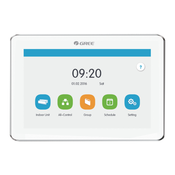
Centralized Controller Main Page Display and Buttons Name Instructions The present date, week and time Time zone Press this button to enter Help Info page Help button Press this button to enter setting page Setting button Press this button to enter Umatch unit page Umatch unit button Press the Touch Button to turn on/off the... -
Page 16: Buttons Working Instructions
Centralized Controller Press this button to Press this button to increase value or select decrease value or Down the previous option select the next option Press this button to Press this button to the return back to previous Right Left next page page On the IDU sort page,... -
Page 17: Functions Description
Centralized Controller (5)Zone button On the management pages of schedule, as indicated in fig.4–2 (the home page of schedule), each rectangle frame constitutes a zone button. Press the zone button, then the turning on/off of corresponding function or the corresponding page will pop in. Figure 4-2 Zone Buttons on the Homepage of Schedule 5 FUNCTIONS DESCRIPTION Help Info... -
Page 18: Single Unit Control
Centralized Controller Name Instructions Display in separate page the list of indoor units that are IDU display controlled by the centralized controller. l Press the button to enter the page of indoor unit control. IDU icon l Light icon indicates that IDU is on while the dark icon indicated that IDU is off. -
Page 19: General Control Parameters
Centralized Controller Parameters of single unit control include parameters of general control and advanced control. 5.3.1 General Control Parameters Figure 5-2 Control Page of Single IDU (1)ON/OFF Press the on/off button to turn unit on or off. When unit is turned off, mode, temperature, fan speed and swing can’t be set. (2)Mode setting Press the Mode buttons to set umatch unit operation mode. -
Page 20: Advanced Control Parameters
Centralized Controller (5)Swing setting Pressing the button “Up&Down Swing” or “Left&Right Swing” can turn on or off the swing function. Note: Swing types for indoor units of different series are not all the same. (6)Malfunction View When indoor unit fails to function well, the will turn red. then press the button to view the information of malfunctions. -
Page 21: Group Control
Centralized Controller Figure 5-4 All-Control Page All-Control Function can operate all indoor units as below: (1)ON/OFF Press ON/OFF button to turn on or turn off all units. When turning off the unit, the setting for mode, temperature, fan speed and swing is unavailable. - Page 22 Centralized Controller Figure 5-5 Group Page Name Instructions Display in separate page the list of groups that are ① Group display controlled by the centralized controller. Sliding up or down can turn over the page. ② Group names Display the names of every group. ③...
-
Page 23: Schedule Management
Centralized Controller (4)Add group Press the button to add new groups. Then the page of group editing will pop in. User can set the group name and add indoor units to the group. (5)Delete group Press to delete the selected group. Schedule Management On the homepage,press button to enter into the page of schedule... - Page 24 Centralized Controller (1)Open the schedule Press the zone button to open or close the schedule. When the icons and texts turn bule indicating the schedule is open. When the icons and texts turn grey indicating the schedule is closed. . When schedule is open, centralized controller will send out the control order automatically according to the time and parameters set by the schedule.
-
Page 25: Umatch Unit
Centralized Controller Umatch Unit 5.7.1 Umatch unit Control On the homepage, press to enter the Control Page. Figure 5-8 Umatch unit homepage Name Instructions Umatch unit display Display the list of units controlled by the central zone controller. Press the button to enter the control page of a single unit. -
Page 26: General Control Parameters
Centralized Controller Display the current umatch unit icon Umatch unit icon Display the current umatch unit name Umatch unit name Before using, press the registration icon and enter the registration page. Register the Umatch units that are going to be controlled. Centralized controller can support the control of 36 units at most. -
Page 27: Advanced Control Parameters
Centralized Controller 2) Heat recollection system have no master indoor unit. When the indoor unit of the same branch is connected into one indoor unit, the auto mode can be set; when the quantity of indoor unit in the same branch is more than one set, the auto mode cannot be set;... -
Page 28: Local Setting
Centralized Controller (3)When All Shield function is enabled, other shield buttons are ineffective. Local Setting Figure 5-11 Setting Page On the homepage,press button to enter into the setting page. Press the “Local Setting” button to switch to the setting options of the current unit. Select the needed option at the left side column. -
Page 29: Engineering Setting
Centralized Controller (5)Backlight setting Pressing this button can set the timeout period of screen backlight. Screen will be shut off and the centralized controller will enter sleep mode when the timeout period is over. Note:When centralized controller is in sleep mode, use can wake it up by touching any part of the touch screen or the touch button at the right bottom of the screen.. -
Page 30: About
Centralized Controller (2)Name&Icon setting Switch to name&Icon setting interface to select the engineering No., and set the name and icon of indoor unit Figure 5-12 Setting Page of Indoor Unit Press the Engineering No. to select the required indoor unit that needs to be set. 1) Name: can input number or letter (it should not be over 10 letters) 2) Icon: press to select the preset icon.
Need help?
Do you have a question about the CE52–24/F(C) and is the answer not in the manual?
Questions and answers