
Related Manuals for Gree CE52-24/F(C)


Summary of Contents for Gree CE52-24/F(C)
- Page 1 Owner's Manual Original Instructions Commercial Air Conditioners Centralized Controller Model: CE52-24/F(C)
- Page 2 To Users Thank you for selecting Gree product. Please read this instruction manual carefully before installing and using the product, so as to master and correctly use the product. In order to guide you to correctly install and use our product and...
-
Page 3: Table Of Contents
Contents 1 Safety Notices (Please be sure to abide) ......1 2 User Notice ................. 1 3 Installation ................2 3.1 Installation Requirements ............3 3.2 Wiring Instructions ..............5 3.3 Installation Procedure ............14 3.4 Removal Procedure .............. 16 4 Display and Working Instructions ........ -
Page 4: Safety Notices (Please Be Sure To Abide)
Centralized Controller 1 Safety Notices (Please be sure to abide) WARNING: If not abide them strictly, it may cause severe damage to the unit or the people. NOTE: If not abide them strictly, it may cause slight or medium damage to the unit or the people. -
Page 5: Installation
Centralized Controller 3 Installation Fig.3.1 Parts of Centralized Controller ① ② ③ ④ Self-tapping screw Touch ST4.2×9.5 MC(used to Rear cover of Rubber Name screen secure the rear cover of controller band controller) ⑤ ⑥ ⑦ ⑧ Screw M4×12 Screw ST4.2×16 FA (used to Electric box Matching... -
Page 6: Installation Requirements
Centralized Controller Unit:mm Fig.3.2 Dimension of Centralized Controller Unit:mm Fig.3.3 Dimension of Electric Box Cover 3.1 Installation Requirements (1) Communication cord of the centralized controller and Multi-VRF (CAN Network) must be selected according to the table below. Never use the cable that is not in compliance with instructions of this manual. - Page 7 Centralized Controller Cord Cord Cord size Total length Network Remark type standard /AWG) L(m/feet) If cord size is 2 × Light/ (2 × AWG16), Ordinary L≤1000m communication cord Indoor polyvinyl (L≤3280-5/6 2 × 0.75~ can be stretched network chloride feet) 2 ×...
-
Page 8: Wiring Instructions
Centralized Controller 3.2 Wiring Instructions 3.2.1 Wiring Ports Port print G1, G2 F1, F2 A2, B2 A3, B3 L, N 【reserved L-CAC&Split Power Meaning comm. fire alarm port port】 unit port port port 3.2.2 Power Supply The centralized controller shall use independent power supply. The range of input voltage: 100~240 VAC;... - Page 9 Centralized Controller Method 2: Connect with outdoor network Fig.3.5 Centralized Controller Connected with Outdoor Network Method 3: Connect with heat recollection mode converter Network Fig. 3.6 Centralized Controller Connected with Heat Recollection Mode Converter Network...
- Page 10 Centralized Controller Wiring Instructions: The centralized controller is applicable to multi VRF units, connectable with network of indoor units or the network of outdoor units. One centralized controller can control up to 16 sets of outdoor system and up to 255 sets of indoor unit.
- Page 11 Centralized Controller Address DIP1 DIP2 DIP3 DIP4 DIP5 5) The centralized control address DIP switch (SA2_Addr-CC) cannot be the same between different refrigerating systems. Otherwise, address conflicts may occur and the unit cannot run properly. NOTES: ① Centralized control address DIP5 invalid. ②...
- Page 12 Centralized Controller ② Press and hold the “Save” button for 5 seconds on the address conflict page, select reset all the IDU’s address in the system, after entering the engineering password, system will reassign all the address. ③ On the master unit of master system, if the mainboard has 7 buttons,press “SW3”...
- Page 13 Centralized Controller Fig. 3.8 Centralized Controller Connected with U-match Unit Fig.3.9 Centralized Controller Connected with PAC Unit Wiring Instructions: The centralized controller is applicable to U-match units (Including PAC units), One centralized controller can control up to 36 U-match units. If the centralized controller is to be connected with U-match units which have COM_BMS ports, connect according to fig.3.7.
- Page 14 Centralized Controller NOTE: If the centralized controller is to be connected with U-match units,communication line(one end is two-core terminal, the other end is the bare wire. Code: 420400060252)need to be purchased separately. The quantity of communication line is the quantity of U-match units plus 1. If the centralized controller is to be connected with U-match units which have 6-core neilsbed, connect according to fig.3.8.
- Page 15 Centralized Controller seconds, system will exit from the setting and return to the display mode of OFF status. Setting can’t be saved in this case. NOTE: Address setting and long-distance monitor setting of unitary units can only be achieved through wired controllers, the setting mode of different remote controllers may be different.
- Page 16 Centralized Controller Wiring Instructions: The connection sketch map of control system is shown by the fig. 3.10. The complete control system is composed of long-distance central controller, wired controller and telecommunication cable. The wired controller matched with long-distance central controller can support 36 addresses of communication node at the most.
-
Page 17: Installation Procedure
Centralized Controller 3.3 Installation Procedure Fig.3.11 Installation Diagram Unit:mm Fig.3.12 Diagram of Wooden or Plastic Plug... - Page 18 Centralized Controller Unit:mm Fig. 3.13 Installation Holes of the Electric Box Rear Cover Fig.3.11 is a simple installation procedure of centralized controller. Please pay attention to the following matters: Before installation, first cut off the power supply of indoor unit. The power must be cut off during the whole installation process.
-
Page 19: Removal Procedure
Centralized Controller In step ⑦, connect the communication cords to G1, G2 terminals, and connect the neutral wire and live wire to the N, L terminal; connect the ground wire to on the electric box rear cover. Secure it with screw M4 × 12. position In step ⑧, locate the controller’s rear cover onto the electric box rear cover with screw ST4.2 ×... -
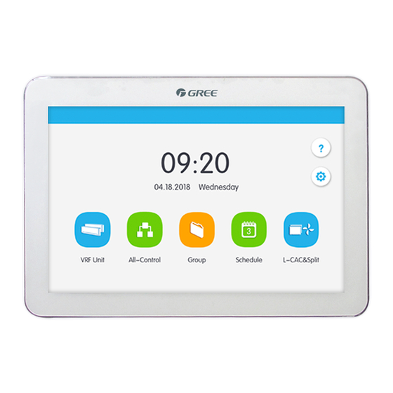
Page 20: Main Page Display And Buttons
Centralized Controller 4.1 Main Page Display and Buttons Name Instructions Time zone The present date, week and time. Help button Press this button to enter Help Info page. Setting button Press this button to enter setting page. L-CAC&Split unit button Press this button to enter L-CAC&Split unit page. -
Page 21: General Buttons
Centralized Controller 4.2 General Buttons Display Name Meaning Display Name Meaning Press this button to Press this button to cancel the Retur return to the Cancel current setting previous page and return to the previous page Press this button to save the current Press this Save... -
Page 22: Buttons Working Instructions
Centralized Controller Display Name Meaning Display Name Meaning On the IDU sort On the IDU sort page, Press Forw Backw page, Press this this button to button to move the move the Page Page selected IDU selected IDU Shift Shift forward one page backward one page... - Page 23 Centralized Controller Meaning of status (take Sleep Button as an example): Thin light indicates invalid/not selectable. Sleep function is invalid and can’t be selected. Different cases for models. Light indicates off/not selected. Sleep function is off. Pressing the grey sleep button can turn on the sleep function. Dark indicates on/selected.
-
Page 24: Functions Description
Centralized Controller 5 Functions Description 5.1 Help Info On the homepage, press to enter into help info page. User can view the information of the simple operation manual. 5.2 VRF Unit On the homepage, press to enter into VRF Unit page. Fig.5.1 Page of VRF Unit Name Instructions... -
Page 25: Single Unit Control
Centralized Controller Name Instructions Error icon will be displayed if indoor unit is Error status malfunctioning. When indoor unit is on, the current operation mode will be displayed: Operation Auto Cooling mode Heating Floor heating Space heating 3D heating This icon will be displayed when indoor unit is in shield Shield status status. - Page 26 Centralized Controller 5.3.1 General Control Parameters Fig.5.2 Control Page of Single IDU (1) ON/OFF Press the on/off button to turn unit on or off. When unit is turned off, mode, temperature, fan speed and swing can’t be set. (2) Mode setting Press the Mode buttons to set operation mode.
- Page 27 Centralized Controller Press the up or down buttons to adjust temperature. Each time pressing the button will increase/decrease the temperature by 1. Holding down the button can increase/decrease temperature continuously. Pressing the button can display the “indoor temp” and “outdoor temp”. (4) Fan speed setting Press the fan speed button to set fan speed.
-
Page 28: Water/Floor Control
Centralized Controller (1) Functions of Sleep, Quiet, Auto Quiet, X-Fan, Absence, Rapid and Save can only be effective when unit is turned on. (2) When sleep function is on, auto quiet function will be turned on subsequently. Sleep function will not be effective under auto, fan or floor heating mode. (3) Absence function can only be turned on in heating mode. - Page 29 Centralized Controller 5.4.1 Water Control Parameter Fig. 5.4 Page of Water heating Control (1) On/Off Press the on/off button to trun unit on or off. When the unit is off, it cannot set the mode, temperature and preset function, while it can set the sterilization function. (2) Mode Setting Press the Mode buttons to set unit’s operation mode.
- Page 30 Centralized Controller Night mode: the fixed period for providing hot water is from 00:00 to 06:00, the water tank or hot water generator will start up in this period, and will decide the on and off of water tank or hot water generator according to the temperature difference between actual water temperature and the setting water temperature.
- Page 31 Centralized Controller Auto function: the setting temperature of water heating will be automatically provided by water heater according to the outdoor ambient temperature, there is no need to set by the user, and the water temperature cannot be adjusted via buttons.
- Page 32 Centralized Controller 5.4.2 Floor control parameter Fig. 5.5 Page of Floor Heating Control (1) On/off Press the on/off button to trun unit on or off. When the unit is off, the mode and temperature cannot be set. (2) Temperature Setting It displays the current water yielding temperature as default.
-
Page 33: Fresh Air Control
Centralized Controller Under the on/off status of floor heating, the functions can be set as below: Floor on/off Function Remarks Auto, Fast, Absence, Floor on Shield It will be valid only when the indoor unit Floor off Absence, Shield is set together with shunt valve. Auto function:the floor heating water yielding temperature will be automatically provided by hot water generator according to the outdoor ambient temperature, there is no need to set by the user, and the water temperature cannot be adjusted... - Page 34 Centralized Controller Fig. 5.6 Page of Fresh Air Control Name Instruction Display indoor PM2.5, CO and humidity. “- -” will be Parameter displayed when air box is not connected ① display zone of Upper and lower limits of PM2.5, CO and humidity air box display keep the same as those in Section 6.2.5...
-
Page 35: All-Control Function
Centralized Controller Note: The fresh air unit which is connected with air box will display PM2.5, CO indoor humidity and air quality class; when air box is not connected, PM2.5, CO and indoor humidity will display “- -”. Air quality class will be concealed. (2)... - Page 36 Centralized Controller When turning off the unit, the setting for mode, temperature, fan speed and swing is unavailable. (2) Mode setting Press mode button to set operation mode. (3) Temperature setting Press UP or Down button to adjust temperature. Press this button once to increase or decrease temperature 1 ℃...
-
Page 37: Group Control
Centralized Controller 5.7 Group Control On the homepage, press to enter into the page of group function. Fig.5.8 Group Page Name Instructions Display in separate page the list of groups that are controlled by the centralized ① Group display controller. Sliding up or down can turn over the page. -
Page 38: Schedule Management
Centralized Controller Press to enter the page of group editing. Use can set the group name and add indoor units to the group. Press to save the setting. NOTE: 1 set of indoor unit can be set in up to 5 groups (3) IDU sort Press the button to enter the IDU sort page. - Page 39 Centralized Controller Fig.5.10 Page of Schedule Editing (1) Open the schedule Press the zone button to open or close the schedule. When the icons and texts turn bule indicating the schedule is open. When the icons and texts turn grey indicating the schedule is closed. When schedule is open, centralized controller will send out the control order automatically according to the time and parameters set by the schedule.
- Page 40 Centralized Controller 3) Repeat schedule Press “Repeat Setting” button to enter the setting page. User can set the schedule work repeatedly according to weeks. 4) Time setting Press the “ON Time” or “OFF Time” button to enter the page of time setting. User can set the time for unit to turn on/off automatically.
-
Page 41: L-Cac&Split Unit
Centralized Controller 5.9 L-CAC&Split Unit 5.9.1 L-CAC&Split unit Control On the homepage, press to enter the Control Page. Fig.5.11 L-CAC&Split unit homepage Name Instructions L-CAC&Split unit Display the list of units controlled by the central display zone controller. Press the button to enter the control page of a single unit. - Page 42 Centralized Controller Name Instructions Icon of sheidling If the unit is in shielding status, this icon will be status shown. L-CAC&Split unit Press the icon to enter the registration page for registration icon the unit. All off button Press the icon to turn off all the units. Page turning Press this icon to turn pages.
- Page 43 Centralized Controller 5.9.2 General Control Parameters Fig.5.12 Control Page of Single IDU (1) ON/OFF Press the On/Off button to turn unit on or off. When unit is off, mode, fan mode and fan speed cannot be set. (2) Mode setting Press the mode icon to set the running mode.
- Page 44 Centralized Controller (6) Malfunction View If unit is malfunctioning, turns red. Press this icon to view detailed information about the malfunction. 5.9.3 Advanced Control Parameters Press the advanced button to enter the advanced page. Press the icons to turn on or off related functions. Fig.5.13 L-CAC&Split unit advanced page (1) The functions of Sleep, Quiet, Blow, Absence, Energy Saving are only effective under ON status.
-
Page 45: Local Setting
Centralized Controller 5.10 Local Setting Fig.5.14 Setting Page On the homepage,press button to enter into the setting page. Press the “Local Setting” button to switch to the setting options of the current unit. Select the needed option at the left side column. Sliding up and down can turn over the page. - Page 46 Centralized Controller When password is activated, it can be set or changed in 4~10 numbers or characters. Original password is blank. Press the button to save the password. NOTE: If user password is activated, user needs to input password to enter the control page when centralized controller is turned on or activated.
-
Page 47: Engineering Setting
Centralized Controller 5.11 Engineering Setting On the home page, press to enter into setting page. Press the “Project Setting” button to switch to engineering setting, the operation method is the same as the setting of this unit. (1) Indoor unit register Enter into the indoor unit register interface, select the chosen indoor unit according to the displayed engineering No. - Page 48 Centralized Controller Press button to successfully save the setting. Then the indoor unit list in the home page will display the new name and icon of indoor units. (3) Advanced Project Settings Press and hold the “Project Setting” button for 5 seconds to display the advanced project settings when “Local Setting”...
-
Page 49: About
Centralized Controller 5.12 About On the home page, press to enter into setting page. Press the “About” button to switch to about page. The operation method is the same with that of the local setting. On the page of about, user can view the information of the local unit, customer service information and other notices.
Need help?
Do you have a question about the CE52-24/F(C) and is the answer not in the manual?
Questions and answers