Advertisement
Quick Links
Advertisement

Related Manuals for Gree XE7A-24/H


Summary of Contents for Gree XE7A-24/H
- Page 1 Owner's Manual Original Instructions Wired Controller XE7A-24/H Wired Controller XE7A-24/HC GREE+...
- Page 2 To Users Thank you for selecting Gree product. Please read this instruction manual carefully before installing and using the product, so as to master and correctly use the product. In order to guide you to correctly install and use our product and achieve expected...
- Page 3 center for professional support. Users should not disassemble or maintain the unit by themselves, otherwise it may cause relative damage, and our company will bear no responsibilities. This marking indicates that this product should not be disposed with other household wastes throughout the EU.
- Page 4 Contents 1 Safety Notices (Please be sure to abide them) ......1 2 Operation Notices ............... 1 3 Display ..................3 3.1 LCD of Wired Controller ............4 3.2 LCD Display Instruction ............4 4 Installation and Commissioning ..........7 4.1 Instruction of wired controller ..........
- Page 5 5.8 Sleep Setting ............... 41 5.9 Air Setting* ................42 5.10 Save Setting ..............43 5.11 Filter Clean Reminder Setting ........... 45 5.12 X-FAN Setting ..............47 5.13 Health Setting* ..............48 5.14 I-DEMAND Setting* ............48 5.15 Absence Setting ..............48 5.16 Remote Shield Function ............
- Page 6 Owner’s Manual 1 Safety Notices (Please be sure to abide them) WARNING: If not abide them strictly, it may cause severe damage to the unit or the people. NOTE: If not abide them strictly, it may cause slight or medium damage to the unit or the people.
- Page 7 Owner’s Manual neutral line. When two wired controllers control one (or more) indoor unit(s), the address of wired controller should be different. Functions with “*” are optional for indoor units. If a function is not included in an indoor unit, wired controller can’t set the function, or setting of this function is invalid to the indoor unit.
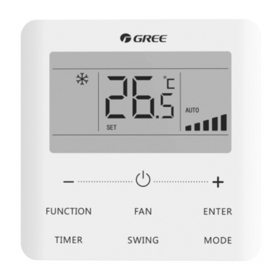
- Page 8 Owner’s Manual when the operation mode of the indoor unit conflicts with the system operation mode after voting. System mode priority defaults to master-slave mode, and only certain units have other system mode priorities. 3 Display Fig. 3.1 Appearance of wired controller...
- Page 9 Owner’s Manual 3.1 LCD of Wired Controller Fig. 3.2 LCD graphics of wired controller 3.2 LCD Display Instruction Table 3.1 LCD display instruction Symbols Instructions Gate-control function. Child Lock status. Slave wired controller (address of wired controller is 02). One wired controller controls multiple indoor units.
- Page 10 Owner’s Manual Symbols Instructions Outdoor unit defrosting status. Shielding status. Current wired controller connects master indoor unit. Fresh air control function of AHU-KIT. Indicates that the current system mode priority is voting mode. WiFi status (If the wired controller has no WiFi function, it displays only when the unit connected to “G-Cloud”).
- Page 11 Owner’s Manual Symbols Instructions Auto clean status. Save status of indoor unit. Air status, Indoor unit optional function. I-DEMAND function, Indoor unit optional function. Quiet status (including Quiet and Auto Quiet two status). Sleep status. Left and right swing function. Up and down swing function.
- Page 12 Owner’s Manual Symbols Instructions Cooling mode. It shows the value of temperature, and displays the current type of value (In case the wired controller is controlling a Fresh Air Indoor Unit, then it will display FAP). NOTE: When wired controller is connected with different indoor units, some functions will be different.
- Page 13 Owner’s Manual Fig. 4.2 Parts and Components of Wired Controller Panel of Soleplate Self-tapping screw Screw Name wired of wired ST3.9×25 MA M4×25 controller controller 4.1 Instruction of wired controller 4.1.1 Requirements for model selection of communication wire Fig. 4.3 Length of communication wire...
- Page 14 Owner’s Manual Wire material Total length Wire size Material Remarks type L (m/feet) /AWG) standard (1) Total length of communication line can't exceed 250m Light/ (820-1/5feet). Ordinary (2) The cord shall be Polyvinyl 2×0.75 Circular cord (the chloride L≤250m ~2× cores shall be twisted sheathed (L≤820-1/5...
- Page 15 Owner’s Manual 4.1.3 Requirements for Wired Connection Network connecting methods between wired controller and indoor unit are as below: Fig. 4.4 one wired controller Fig. 4.5 two wired controllers controls one indoor unit control one indoor unit...
- Page 16 Owner’s Manual Fig. 4.6 one wired controller controls multiple VRF indoor units simultaneously Fig. 4.7 two wired controllers control multiple VRF indoor units simultaneously...
- Page 17 Owner’s Manual Fig. 4.8 one wired controller controls multiple U-match indoor units simultaneously Fig. 4.9 two wired controller control multiple U-match indoor units simultaneously...
- Page 18 Owner’s Manual Instruction for wire connection: The wiring methods in fig. 4.4, fig. 4.5, fig. 4.8 and fig. 4.9 can be adopted for the wired controller connecting U-match unit. The wiring methods in fig. 4.4~fig. 4.7 can be adopted for the wired controller connecting VRF unit.
- Page 19 Owner’s Manual indoor unit(s) controlled by one wired controller. 4.1.4 Installation Fig. 4.10 Installation of Wired Controller Fig. 4.10 shows a simple installation course of wired controller, and the following points should be noted:...
- Page 20 Owner’s Manual Before installation, please cut off the power supply of indoor unit, it is not allowed to operate with power supply; Pull out the 2-core twisted pair inside the installation hole in the wall, and thread the wire through the hole in the back of soleplate of wired controller;...
- Page 21 Owner’s Manual 4.2 Commissioning 4.2.1 Set Master Indoor Unit Under Off status, long press “MODE” button for 5s to set the corresponding indoor unit of wired controller as master indoor unit. If the system mode priority is the master-slave mode, “ ”...
- Page 22 Owner’s Manual Table 4.1 Parameters viewing list Parameter Parameter Parameter Viewing method code name range Press “MODE” button in “C01” status. Press “+” or “-” button to select the project number of indoor unit. The current selected indoor unit will beep. View the Temperature zone: displays project...
- Page 23 Owner’s Manual Parameter Parameter Parameter Viewing method code name range View the indoor unit Timer zone: display indoor quantity of 1-100 unit quantity of the system. the system network* Operation method: Enter viewing: press “MODE” button in “C06” status to enter the interface of viewing priority operation.
- Page 24 Owner’s Manual Parameter Parameter Parameter Viewing method code name range Enter viewing: press “MODE” button in “C07” status. Press “+” or “-” button to select View indoor indoor unit. ambient — Temperature zone: displays temperature current indoor unit project number; Timer zone: displays indoor ambient temperature.
- Page 25 Owner’s Manual Parameter Parameter Parameter Viewing method code name range View the Timer zone: displays the indoor unit 1-16 indoor unit quantity controlled quantity by the wired controller. View outdoor Timer zone: displays outdoor — ambient ambient temperature. temperature Press “MODE” button to enter into the review interface of indoor relative humidity under 0~100:...
- Page 26 Owner’s Manual Parameter Parameter Parameter Viewing method code name range Press “MODE” button in “C18” status to turn on the function of one-button viewing indoor unit project code. Press “+” or “-” button to select the indoor unit. Temperature zone: displays number of the current indoor unit One-button...
- Page 27 Owner’s Manual Parameter Parameter Parameter Viewing method code name range Cancel method: 1)If user exits the “C18” interface manually, the one-button viewing function will be immediately turned off. 2)If system exits the “C18” interface due to no action in 20 seconds, user has to One-button 1-255: press the “...
- Page 28 Owner’s Manual Parameter Parameter Parameter Viewing method code name range Enter viewing, short-press “MODE” button in “C20” status. Press “+” or “-” button to select the indoor unit. View the air Temperature zone: displays outlet current indoor unit project temperature —...
- Page 29 Owner’s Manual (1) Long press “FUNCTION” button for 5s and the temperature zone displays “C00”; long press “FUNCTION” button for another 5s to enter the interface of setting wired controller parameters. “P00” is displayed in temperature zone; (2) Press “+” or “-” button to select parameter code. Press “MODE”...
- Page 30 Owner’s Manual Parameter Parameter Default Parameter name Note code range value Set infrared 00: forbidden receiver of — 01: activated wired controller Assistant wired 01: master controller (02) is Set address of wired controller without unit parameter wired controller 02: slave wired setting function except controller setting its address.
- Page 31 Owner’s Manual Parameter Parameter Default Parameter name Note code range value Set static 01-09: static pressure of pressure level — indoor fan of indoor fan motor motor 00: standard High ceiling Only applicable to ceiling installation* partial cassette units. 01: high ceiling 00: general NOTE: not applicable Set Timer*...
- Page 32 Owner’s Manual Parameter Parameter Default Parameter name Note code range value Cooling setting temperature 17°C~30°C 25°C under auto (63°F~86°F) (77°F) When the temperature mode* unit is °C, cooling setting temperature minus heating setting temperature≥1°C. When the temperature unit is °F, cooling setting temperature Heating setting minus heating setting...
- Page 33 Owner’s Manual Parameter Parameter Default Parameter name Note code range value When power supply is insufficient, the indoor 00: normal units which are set to Set priority operation priority operation can operation* 01: priority operate, while other operation indoor units are forced to be turned off.
- Page 34 Owner’s Manual Parameter Parameter Default Parameter name Note code range value Air outlet temperature 16°C~30°C 22°C Only applicable to setting for Fresh (61°F~86°F) (71°F) Fresh Air Indoor Unit. Air Indoor Unit in heating* After union function is set, Fresh Air Indoor Unit will be turned 00: without Union setting of...
- Page 35 Owner’s Manual Parameter Parameter Default Parameter name Note code range value When it is set as 00, it will keep the status When inserting after inserting the gate the card, control card, that is, if 00: no whether to it is OFF status when 01: yes resume to pulling out the card,...
- Page 36 Owner’s Manual Parameter Parameter Default Parameter name Note code range value When it is set as 01 and the timer setting way is clock timer, the 00: 24-hour system time in the Set time format 01: 12-hour homepage will be displayed in 12 hour-clock with the AM/PM indicator.
- Page 37 Owner’s Manual Parameter Parameter Default Parameter name Note code range value NOTE: Only Set temperature applicable to the unit of humidity 10℃~30℃ 16℃ with humidity control control under (50°F~86°F) (61°F) function under Dry Dry mode mode. NOTE: Only 01: Normal Auto clean applicable to the unit 02: Quick...
- Page 38 Owner’s Manual 5 Operation Instructions 5.1 ON/OFF Press “ ” button to turn on the unit. Press “ ” button again to turn off the unit. The interfaces of “ON/OFF” status are shown in fig. 5.1 ~ 5.2. Fig. 5.1 Interface of On status Fig.
- Page 39 Owner’s Manual to the model of indoor unit. ② When the wired controller controls VRF unit and the system mode priority is the master-slave mode, only the master indoor unit can set the auto mode. ③ Under Auto mode, if the indoor unit is running under Cooling, the icons “...
- Page 40 Owner’s Manual the setting temperature be adjusted by pressing “+” or “-” under Auto mode. ② When Absence function is activated, the setting temperature cannot be adjusted by pressing “+” or “-”. ③ When the wired controller is connected with a Fresh Air Indoor Unit, fresh air indoor unit code “FAP”...
- Page 41 Owner’s Manual When Turbo function is activated, Turbo function icon “ ” will be bright. NOTES: ① Under Dry mode, fan speed is low and can’t be adjusted. ② When the wired controller is connected with a Fresh Air Indoor Unit, fan speed of indoor unit will be high fan speed only.
- Page 42 Owner’s Manual decrease timer time by 0.5h every 0.3s. 5.5.2 Clock Setting Clock display: when the timer setting way is clock timer, timer zone displays system clock in unit On and Off status. The clock can be set at this time. Clock setting: long press “TIMER”...
- Page 43 Owner’s Manual button again to switch to the setting of unit ON time or unit Off time; press “ENTER” button to cancel timer. Press “+” or “-” button to increase or decrease timer time by 1min; hold “+” or “-” button for 5s to increase or decrease timer time by 10min;...
- Page 44 Owner’s Manual Fig. 5.3 Unit On/Off time setting in unit On status...
- Page 45 Owner’s Manual NOTE: It is not applicable to partial units. 5.6 Swing Setting In unit on status, up & down swing function and left & right swing function can be set. (1) Up & down swing function Up & down swing function has two modes: simple swing mode and fixed-angle swing mode.
- Page 46 Owner’s Manual the quiet effect. Quiet function has two modes: Quiet mode and Auto Quiet mode. It is available only in Auto, Cooling, Dry, Fan, Heating, 3D heating, Space heating mode. Turn on Quiet Function: press “FUNCTION” button to turn to Quiet function and then Quiet icon “...
- Page 47 Owner’s Manual auto quiet mode is also activated. Under Auto, Fan or Floor Heating mode, the Sleep function is not available. 5.9 Air Setting* Air Function: Adjust the amount of indoor fresh air to improve air quality and keep indoor air fresh. Turn on Air Function: When unit is on or off, press “FUNCTION”...
- Page 48 Owner’s Manual Level of Air setting Opening time of fresh air Always on valve NOTE: time indicated in the table: unit’s operating time (min) / opening time of fresh air valve per operating time (min). 5.10 Save Setting Save Function: Air conditioner can be operated in small temperature range by setting the minimum temperature under Cooling and Dry modes and setting maximum temperature under Heating, 3D Heating and Space Heating modes.
- Page 49 Owner’s Manual Fig. 5.4 shows how to set Save function for Cooling: Fig. 5.4 Save Setting for Cooling...
- Page 50 Owner’s Manual Start up Save function for Heating: When the unit is off, simultaneously press “TIMER” and “+” buttons for 5s, the buzzer will give out a sound and then unit will enter into Save setting mode. “ ” icon is blinking. Mode icon is on. Press “MODE” button to switch to Heating or 3D Heating or Space Heating mode.
- Page 51 Owner’s Manual range is 00, 10-39. Press “ENTER” to turn on this function. Turn off Filter Clean Reminder Function: When unit is on and this function has been turned on, press “FUNCTION” button and select Clean. Then “ ” icon will blink. Set the cleaning level as 00 and press “ENTER”...
- Page 52 Owner’s Manual Cleaning Description of Levels Level Turn off Timer zone shows 00 Clean The former digit shows 1 while the latter one shows 0, which indicates the accumulating operating time is 5500 Slight hours. Each time the latter digit increases 1, the operating Pollution time increases 500 hours.
- Page 53 Owner’s Manual Under Cooling or Dry mode, press “FUNCTION” button to select X-fan. “ ” icon will blink. Then press “ENTER” button to turn on/off this function. 5.13 Health Setting* Health Function: Control the air purification module which can purify air. This function cannot be used under Floor Heating mode. When unit is on, press “FUNCTION”...
- Page 54 Owner’s Manual 5.16 Remote Shield Function Remote Shield Function: Remote monitor or central controller can disable the relevant functions of wired controller so as to realize the function of remote control. When the remote monitor or central controller activates Remote Shield on the wired controller, “...
- Page 55 Owner’s Manual used with wired controller that includes gate control signal detecting function (used as master and salve wired controller). 5.19 Inquiry of Indoor Temperature with One Button In the homepage, hold “ENTER” button for 5 seconds, and the wired controller will display the indoor temperature for 5 seconds. Within the 5 seconds, it can quit displaying the indoor temperature immediately and be responded to the instructions as usual after pressing any buttons.
- Page 56 Owner’s Manual Fig. 5.5 Turn on Auto Clean function NOTES: This function is only applicable to the unit with Auto Clean ① function. When the unit is faulty, Auto Clean function cannot be ② turned on. During Auto Clean function is on, there will be ③...
- Page 57 5.21 WiFi Function Setting "GREE+" App can be used to control wired controller XE7A-24/HC. Please scan the QR code or search "GREE+" in the application market to download and install it. When "GREE+" App is installed, register the account and add the device to achieve long-distance control and LAN control of Gree smart home appliances.
- Page 58 Owner’s Manual the unit is off, hold “FUNCTION” and “FAN” buttons for 5 seconds in the homepage; when the temperature display area displays “oC” for 5 seconds, it indicates that the current reset is valid. Then add the device in APP. NOTES: This function is only applicable to wired controller ①...
- Page 59 Owner’s Manual professionals to repair. Fig. 6.1 is the display of Outdoor Unit High Pressure Protection when unit is on. Fig. 6.1 Display of Outdoor Unit High Pressure Protection 6.1 Table of Display Codes for VRF unit 6.1.1 Table of Error Codes for Outdoor Unit Error Error Content...
- Page 60 Owner’s Manual Error Error Content Content Code Code Bad Performance of the Low Water-in Temperature Outdoor Mainboard Protection High Pressure Sensor Outdoor Ambient Error Temperature Sensor Error Inlet Tube Temperature Defrosting Temperature Sensor Error of Plate Sensor 1 Error Type Heat Exchanger Low Pressure Sensor Defrosting Temperature Error...
- Page 61 Owner’s Manual Error Error Content Content Code Code Compressor 6 Discharge Oil-return Temperature Temperature Sensor Sensor Error Error Compressor 2 Current System Clock Malfunction Sensor Error Malfunction of Entry Tube Compressor 3 Current Temperature Sensor of Sensor Error Condenser Malfunction of Exit Tube Compressor 4 Current Temperature Sensor of Sensor Error...
- Page 62 Owner’s Manual Error Error Content Content Code Code Mode Exchanger Inlet Water-out Temperature Pipe Temperature Sensor Sensor Error Error Water-in Temperature Compressor Drive Board Sensor Error Error Compressor 1 Compressor Drive Board Over-current Protection Malfunction Compressor 2 Protection of Compressor Over-current Protection Drive Board Power Supply Compressor 3...
- Page 63 Owner’s Manual Error Error Content Content Code Code Indoor Unit CO Sensor Indoor Fan Protection Error Special Code: Field E-heater Protection Debugging Code Water Full Protection Swing Assembly Error Wired Controller Power Water Temperature Sensor Supply Error Error Inlet Pipe Temperature Anti-Frosting Protection Sensor 2 Error Outlet Pipe Temperature...
- Page 64 Owner’s Manual Error Error Content Content Code Code Zero-crossing High Liquid Level Switch Malfunction of PG Motor Error Inconsistent Branch of Group-controlled Indoor Low Liquid Level Switch Units in Heat Recovery Error System Inconsistency of Group-controlled Indoor Motor Drive Error Units in Reheat Dehumidification System Indoor Fan 2 Error...
- Page 65 Owner’s Manual Error Error Content Content Code Code Water Temperature Communication Error of IDU Abnormality Master Controller High Temperature of IDU Jumper Cap Error Module Indoor Unit Hardware IDU Charging Circuit Error Address Error Wired Controller Temperature Sensor Error PC-Board Error of IDU Module Capacity DIP Switch —...
- Page 66 Owner’s Manual Error Error Content Content Code Code Communication error Wrong Address of between master control and Compressor Drive Board inverter fan motor drive Valve Abnormal Alarm Error of Lack of Indoor Unit Grid DRED0 Response Alarm of Indoor Unit Project Protection Number Collision Indoor Unit Tube...
- Page 67 Owner’s Manual Error Error Content Content Code Code Protection shutdown error Communication Error of thermal storage between Indoor Unit and module Remote Receiver Electronic expansion valve leak error of Outflow of Units IP Address thermal storage module Protection without Communication Failure shutdown error of thermal Between Mode Exchanger storage module...
- Page 68 Owner’s Manual Error Error Content Content Code Code Select degree Celsius or Defrosting Fahrenheit Discharge low temperature Oil return protection revision value b Online Testing Setting of defrosting mode Vacuum-pumping Mode Setting of static pressure Operate in Setback EVI Operating Mode Function System compulsory cooling Heating...
- Page 69 Owner’s Manual 6.2 Table of Display Codes for U-match unit 6.2.1 Table of Error Codes of Outdoor Unit Error Error Content Content Code Code Discharge Protection Outdoor Fan 2 Error Overload Protection Outdoor Fan 1 Error ODU AC Current System Low Pressure Protection Protection System High Pressure...
- Page 70 Owner’s Manual Error Error Content Content Code Code Overcurrent of Compressor Drive Module Reset Phase Current Overspeed DC Input Voltage Error Abnormal Outdoor Ambient Temperature (heating at too Compressor DIP high ambient temperature or Switch/Jumper Cap Error cooling at too low ambient temperature) Drive Board Ambient Liquid Valve Temperature...
- Page 71 Owner’s Manual Error Error Content Content Code Code Compressor Drive Storage Communication Error Chip Error between ODU and IDU Outdoor Fan Out-of-phase ODU Jumper Cap Error Protection AC Phase Sequence Outdoor Fan Current Protection (phase loss or Detecting Circuit Error phase reversal) Outdoor Fan Startup High Pressure Sensor Error...
- Page 72 Owner’s Manual 6.2.2 Table of Error Codes of Indoor Unit Error Error Content Content Code Code Indoor Fan Error Indoor Humidity Sensor Error Inverter Indoor Fan Drive Main Control and Inverter Current Detecting Circuit Indoor Fan Drive Error Communication Error Inverter Indoor Fan Drive Indoor Ambient Module High Temperature...
- Page 73 Owner’s Manual Error Error Content Content Code Code Inverter Indoor Fan AC Communication Error Current Protection (input between Indoor Unit and side) Wired Controller Inverter Indoor Fan Drive Inverter Indoor Fan PFC Protection Non-synchronism Protection Inverter Indoor Fan Refrigerant Lacking Startup Failure Protection Inverter Indoor Fan...
- Page 74 Owner’s Manual 6.2.3 Table of Status Codes Status Status Content Content Code Code Auto clean DRED operation mode 1 Refrigerant recycle mode DRED operation mode 2 Ordinary defrosting status DRED operation mode 3...
Need help?
Do you have a question about the XE7A-24/H and is the answer not in the manual?
Questions and answers