Table of Contents
Advertisement
Change for life
Smart Zone Controller
Installation Manual
Commercial Air Conditioners
Thank you for choosing Commercial Air Conditioners, please read this owner's manual
carefully before operation and retain it for future reference.
GREE reserves the right to interpret this manual which will be subject to any change due
to product improvement without further notice.
GREE Electric Appliances, Inc. of Zhuhai reserves the final right to interpret this manual.
Advertisement
Table of Contents

Related Manuals for Gree CE50-24/E


Summary of Contents for Gree CE50-24/E
- Page 1 Thank you for choosing Commercial Air Conditioners, please read this owner’s manual carefully before operation and retain it for future reference. GREE reserves the right to interpret this manual which will be subject to any change due to product improvement without further notice.
-
Page 2: Table Of Contents
CONTENTS 1 Safety Precautions ..................1 2 General Introduction ..................2 2.1 Function Introduction .................. 2 2.2 Communication Network ................3 3 LCD ......................... 4 3.1 Outline of the LCD ..................4 3.2 Introduction to Symbols on the LCD ............4 4 Buttons ...................... -
Page 3: Safety Precautions
Floor Ceiling Air-Conditioning Unit 1 Safety Precautions This mark indicates procedures which, if improperly performed, might lead to WARNING! the death or serious injury of the user. This mark indicates procedures which, if improperly performed, might possibly CAUTION! result in personal harm to the user, or damage to property. WARNING! For operating the air conditioner pleasantly, install it as outlined in this installation manual. -
Page 4: General Introduction
Floor Ceiling Air-Conditioning Unit 2 General Introduction 2.1 Function Introduction This smart zone controller is intended for VRF, free-match and ducttype unit, capable of controlling up to 3 sets of multi VRF units and multi sets of duct type/ free match units with maximum 16 indoor units. -
Page 5: Communication Network
Floor Ceiling Air-Conditioning Unit 2.2 Communication Network 2.2.1 Units Connection Fig.2.1 Unit Connection Diagram Note: the smart zone controller can connect with maximum three sets of multi VRF units and multiple duct type units, however, the total of the indoor units of all four ports can not exceed 16. 2.2.2 Integration of the Smart Zone Controller and Long-distance Monitoring System/ Centralized Controller PC &... -
Page 6: Lcd
Floor Ceiling Air-Conditioning Unit Notes: Only the multi VRF units can be integrated with the long-distance monitoring system/ ① . centralized controller. When the shielding function has been set neither for the smart zone controller nor for the ② . long-distance monitoring system/the centralized controller, the smart zone controller can fully be compatible with the long-distance monitoring system/the centralized controller with its control inferior to that of the latter ones. -
Page 7: Buttons
Floor Ceiling Air-Conditioning Unit Table 3.1: Introduction to the Symbols on the LCD Name Description It displays the fan speed of the indoor unit, high, medium, low and Fan speed auto. It displays the running mode of the indoor unit, auto, cool, dry, fan Running mode and heat. -
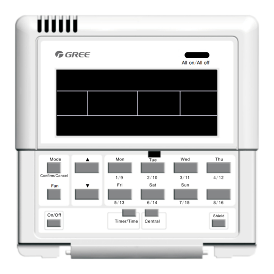
Page 8: Introduction To The Function Of Buttons
Floor Ceiling Air-Conditioning Unit 4.2 Introduction to the Function of Buttons Table 4.1 Functions of Buttons Name Function Description Mode It is used for the switchover among different modes It is used to set the fan speed, high, medium, low or auto. On/Off It is used to set the on/off status of the indoor unit. -
Page 9: Installation And Debugging
Floor Ceiling Air-Conditioning Unit 5 Installation and Debugging 5.1 Installation 5.1.1 Installation Dimension Diagram Fig.5.1 Installation Dimensions Diagram 5.1.2 Interfaces See Fig.5.2 for the interfaces of the display board and see Fig.4.3 for the interfaces of the power supply module. +9.8V COM1 COM2... - Page 10 Preparation and connection of the communication line for the duct type unit The communication line for the duct type unit is the two-core line provided by Gree (one ①...
- Page 11 Floor Ceiling Air-Conditioning Unit Fig.5.4 Concealed Cable Installation 1 (right-left wiring) Fig.5.5 Concealed Cable Installation 2 (up-down wiring) Note: the power cord must be separated from the communication line to avoid any interference. Hole for the power cord Hole for the communication line Fig. 5.6 Installation Diagram...
-
Page 12: Unit Matching
Floor Ceiling Air-Conditioning Unit Serial No. Description Wall Power Supply Box (86) Bottom Base(including power supply module board) Screw Top Cover(including the display board) After the installation, it is necessary to make the debugging to guarantee the normal communication. 5.2 Unit Matching Provided that only the multi VRF unit is needed for some project, for the outdoor unit with the connection board, one smart zone controller can control maximum 16 indoor units matched with maximum three connection boards;... -
Page 13: Debugging And Viewing The Port No. And The Indoor Unit Address
Floor Ceiling Air-Conditioning Unit 5.3 Debugging and Viewing the Port No. and the Indoor Unit Address Debugging setting: In the event that the unit is initially powered on, the setting for the project changes, or the serial port is replaced, and then it is available to go to the debugging status by pressing “Mode”... -
Page 14: Labeling
Floor Ceiling Air-Conditioning Unit 5.4 Labeling A label is provided to identify the relationship of the indoor unit No. and the corresponding room name. The user can write down the indoor unit No. and its corresponding room name on the label which then will be stuck to the inside of the cover of the smart zone controller so that the user can be clear about the control object. -
Page 15: Control Flow Chart
Floor Ceiling Air-Conditioning Unit 6 Control Flow Chart See the following figure for the control flow chart of the smart zone controller. No press operation in 30 seconds Set the control comma nd (No press operation in 2.5 seconds) Center Send out the control command Single Centralized... -
Page 16: Control Mode
Floor Ceiling Air-Conditioning Unit See Fig.7.1 for how to view the running status of the indoor unit. Fig.7.1 Viewing of the Running Status of the Indoor Unit 7.2 Control Mode 7.2.1 Single Control Select the expected indoor unit through the indoor unit code button and then the code on the LCD will flash. - Page 17 Floor Ceiling Air-Conditioning Unit See Fig. 7.2 for the temperature control under the single control: on/ All on/ All on/ All on/ All AUTO AUTO TUE WED THU FRI SAT TUE WED THU FRI SAT ROOM ROOM SET INNER UNIT TEMP ROOM ROOM...
-
Page 18: Control Setting
Floor Ceiling Air-Conditioning Unit See Fig. 7.4 for the centralized control to the temperature: Fig.7.4 Centralized Temperature Control For other settings, please refer to the following sections. 7.2.3 All on/off In any case, the current indoor unit which is on/off will be turned off/on by pressing “All on/off” with “CENTER”... - Page 19 Floor Ceiling Air-Conditioning Unit 7.3.2 Mode Under the On state of the unit, whenever it is in single or centralized control, the running mode will change circularly as the following sequence by pressing “Mode”. Cool Heat See Fig.7.5 for how to set the running mode. Al l Al l on /Al l...
- Page 20 Floor Ceiling Air-Conditioning Unit 7.3.4 Fan Under the On state of the unit, whenever it is in single or centralized control, the fan speed will change circularly as the following sequence by pressing “Fan”. See Fig.7.7 for how to set the fan speed: Auto Medium High...
- Page 21 Floor Ceiling Air-Conditioning Unit unit will be automatically turned on at 15:30 and later turned off at 21:30. 7.3.5.1 How to Set the Weekly Timer under the Single Control It is available to go to the weekly timer setting page by pressing “Timer/Time” under the single control mode, with “*”...
- Page 22 Floor Ceiling Air-Conditioning Unit Fig.7.8 How to Set the Weekly Timer under the Single Control 7.3.5.2 How to Cancel the Weekly Timer under the Single Control It is available to go to the weekly timing setting page by pressing “Timer/Time” under the single control mode, with “*”flashing (“*”...
- Page 23 Floor Ceiling Air-Conditioning Unit Fig.7.9 How to Cancel the Weekly Timer under the Single Control 7.3.5.3 How to Set the Weekly Timer under the Centralized Control It is available to go to the weekly timing setting page by pressing “Timer/Time” under the single control mode , with “*”...
- Page 24 Floor Ceiling Air-Conditioning Unit...
- Page 25 Floor Ceiling Air-Conditioning Unit Al l Al l on / Al l on / Al l AUTO TUE WED THU FRIS AT ROOM ROOM S SET INNER UNIT TEMP CH LD LOCK SHIELD MODE ERROR ON/OFF 1 2 34 SUNM ON TUEW ED THUF RI SAT CENTER 10 12 14 16 18 20 22 24 10 12 14 16 18 20 22 24...
- Page 26 Floor Ceiling Air-Conditioning Unit on/ All on/ All on/ All on/ All AUTO AUTO TUE WED THU FRI SAT TUE WED THU FRI SAT ROOM ROOM SET INNER UNIT TEMP CH LD LOCK ROOM SET INNER UNIT ROOM SHIELD MODE TEMP ERROR CH LD LOCK...
- Page 27 Floor Ceiling Air-Conditioning Unit on/ All on/ All on/ All on/ All AUTO AUTO TUE WED THU FRI SAT TUE WED THU FRI SAT ROOM ROOM SET INNER UNIT TEMP ROOM ROOM SET INNER UNIT TEMP CH LD LOCK CH LD LOCK SHIELD MODE SHIELD...
- Page 28 Floor Ceiling Air-Conditioning Unit 7.3.7 Shield The shield function can be set under either single control or the centralized control and the control command (including,: On/Off,, Mode, Fan, ▲/ ▼, and Shield etc.) based on the settings of the current indoor unit will be sent out to all online indoor units 2.5 seconds later.. 7.3.7.1 “TEMP”...
- Page 29 Floor Ceiling Air-Conditioning Unit quit this setting status by pressing “Shield” twice. on/ All on/ All on/All on/All AUTO AUTO TUE WED THU FRI SAT TUE WED THU FRI SAT ROOM ROOM SET INNER UNIT ROOM ROOM SET INNER UNIT TEMP TEMP CH LD LOCK...
- Page 30 Floor Ceiling Air-Conditioning Unit Fig.7.15 “ON/OFF” Shield under the Singe Control 7.3.7.4 “ALL” Shield under the Single Control It is available to activate or deactivate the All shield: first press “Shield” with “SHILED” displayed on the LCD, next press it to switch to “ALL”, and then press “Confirm/Cancel”, after that, “ON/OFF” will go on or go out and meanwhile quit this setting status.
- Page 31 Floor Ceiling Air-Conditioning Unit See Fig.7.16 for “ALL” Shield under the single control: on/All on/All on/All on/All AUTO AUTO TUE WED THU FRI SAT TUE WED THU FRI SAT ROOM ROOM SET INNER UNIT TEMP ROOM ROOM SET INNER UNIT TEMP CH LD LOCK CH LD LOCK...
- Page 32 Floor Ceiling Air-Conditioning Unit on/ All on/ All on/ All on/ All AUTO AUTO TUE WED THU FRI SAT TUE WED THU FRI SAT ROOM ROOM SET INNER UNIT TEMP TEMP ROOM ROOM SET INNER UNIT CH LD LOCK TEMP TEMP CH LD LOCK SHIELD...
- Page 33 Floor Ceiling Air-Conditioning Unit on/All on/All on/All on/All AUTO AUTO TUE WED THU FRI SAT TUE WED THU FRI SAT ROOM ROOM SET INNER UNIT TEMP ROOM ROOM SET INNER UNIT CH LD LOCK TEMP CH LD LOCK SHIELD SHIELD MODE MODE ERROR...
- Page 34 Floor Ceiling Air-Conditioning Unit on/All on/A l on/ All on/ A l Quit this setting status automatically 30 Press “Confirm/Cancel” to seconds later or by pressing “Shield” activate / deactivate the shielding once. function. Fig.7.19 “ON/OFF” Shield under the Centralized Control 7.3.7.8 “ALL”...
- Page 35 Floor Ceiling Air-Conditioning Unit Press “Confirm/Cancel” to activate / deactivate the shielding function and meanwhile quit this setting status. Fig.7.20 “ALL” Shield under the Centralized Control Note: if the shield setting is not confirmed by pressing “Confirm/Cancel”, the system will quit this setting status 30 seconds later.
-
Page 36: Error Display
Floor Ceiling Air-Conditioning Unit 7.3.9 Switchover between Celsius and Fahrenheit Under the off status of the current indoor unit, symbols of Celsius and Fahrenheit can be switched over by pressing “Mode” and ““▼” simultaneously for five seconds. See Fig.7.22 for the switchover between Celsius and Fahrenheit. 8 Error Display When some error arises during the operation of the system, error codes will be displayed where the ambient temperature once is displayed on the LCD. - Page 37 Floor Ceiling Air-Conditioning Unit Table 8.1 Errors for Multi VRF Indoor Units Code Description High pressure protection of the compressor Anti-freezing protection of the indoor unit Low pressure protection of the compressor Discharge temperature protection of the compressor Over-current protection, overload protection of compressor, drive error Communication error Mode conflict Water overflow protection...
- Page 38 Floor Ceiling Air-Conditioning Unit Table 8.2 Errors for the Duct Type Indoor Unit Code Description Water pump error High pressure protection of the compressor Anti-freezing protection of the indoor unit Low pressure protection of the compressor High discharge temperature protection of the compressor Overload protection of the compressor Communication error Indoor unit fan protection...
- Page 39 Floor Ceiling Air-Conditioning Unit Table 8.3 Error Code of Free Match Code Description High pressure protection Anti-freezing protection Low pressure protection High discharge temperature protection Whole unit over-current protection Indoor and outdoor communication error Overload protection Indoor unit full water error System charge shortage or blockage protection Return air temperature sensor open/short circuited evaporator temperature sensor open/short circuited...
- Page 40 GREE ELECTRIC APPLIANCES, INC. OF ZHUHAI Add: West Jinji Rd, Qianshan, Zhuhai, Guangdong, China, 519070 Tel: (+86-756) 8522218 Fax: (+86-756) 8669426 E-mail: gree@gree.com.cn www.gree.com...
Need help?
Do you have a question about the CE50-24/E and is the answer not in the manual?
Questions and answers