Table of Contents
Advertisement
●Thank you for choosing Commercial Air Conditioners ,please read this owner's manual carefully before
operation and retain it for future reference.
●GREE reserves the right to interpret this manual which will be subject to any change due to product
improvement without further notice.
●GREE Electric Appliances, Inc. of Zhuhai reserves the final right to interpret this manual.
Wired Controller XK49
Owner's Manual
Commercial Air Conditioners
Advertisement
Table of Contents

Related Manuals for Gree XK49


Summary of Contents for Gree XK49
- Page 1 ●Thank you for choosing Commercial Air Conditioners ,please read this owner’s manual carefully before operation and retain it for future reference. ●GREE reserves the right to interpret this manual which will be subject to any change due to product improvement without further notice.
- Page 2 User Notices ◆The power supply for all indoor units must be unified. ◆Prohibit installing the wired controller at wet or sunshine places. ◆Do not knock, throw or frequently disassemble the wired controller. ◆Do not operate the wired controller with wet hands. ◆In one system network, you must set one indoor unit as the master indoor unit, Other indoor units are slave indoor units .
-
Page 3: Table Of Contents
ONTENTS 1. DISPLAY ......................... 1 1.1 LCD ................1 IRED ONTROLLER 1.2 LCD D ................2 ISPLAY NSTRUCTION 2. BUTTONS ....................... 3 2.1 B .................... 3 UTTON RAPHICS 2.2 F .............. 3 UNCTION NSTRUCTION OF UTTONS 3. INSTALLATION AND COMMISSIONING ............3 3.1 I ............ -
Page 4: Display
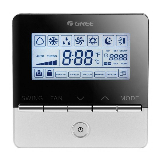
Wired Controller XK49 1. DISPLAY Fig. 1.1 Appearance of wired controller 1.1 LCD of Wired Controller Fig. 1.2 LCD graphics of wired controller... -
Page 5: Lcd Display Instruction
Wired Controller XK49 1.2 LCD Display Instruction Table 1.1 LCD display instruction Symbols Instructions Auto mode (Under Auto mode, the indoor units will automatically select their operating mode as per the temperature change so as to make the ambient comfortable.) -
Page 6: Buttons
Wired Controller XK49 2. BUTTONS 2.1 Button Graphics Fig. 2.1 Button graphics 2.2 Function Instruction of Buttons Table 2.1 Function instruction of buttons Buttons Instructions It’s used to set swing status. SWING Switch among auto, low speed, low-medium speed, medium speed, medium-high... -
Page 7: Installation Of Wired Controller
Wired Controller XK49 Fig. 3.2 Parts of wired controller Junction box embedded in Soleplate of wired Screw Panel of wired Name the wall controller M4*25 controller Q'ty User-supplied 3.1 Installation of Wired Controller 3.1.1 Communication Line Selection Fig. 3.3 Length of communication line... -
Page 8: Installation Requirements
Wired Controller XK49 Note: ① If the air conditioner is installed at the strong electromagnetic interference place, communication line of the wired controller must use shielding twisted pair. ② Materials of communication line for wired controller must be selected according to this instruction manual strictly. - Page 9 Wired Controller XK49 Fig. 3.6 One wired controller controls multiple indoor units simultaneously Fig. 3.7 Two wired controllers control multiple indoor units simultaneously Wiring instructions: (1) When one wired controller controls multiple indoor units simultaneously, the wired controller can connect to any one indoor unit, but the connected indoor unit must be the same series indoor unit.
- Page 10 Wired Controller XK49 two wired controllers should be different. Please refer to 3.2.3 parameter setting. (3) When two wired controllers control multiple indoor units, wired controller can connected to any one indoor unit, while the connected indoor unit should be the same series indoor unit.
- Page 11 Wired Controller XK49 Figure 3.8 Wrong Connection 1 Figure 3.9 Wrong Connection 2 of Units and Gate Control of Units and Gate Control 2) After wired controller is connected with gate-control device, indoor unit’s on and off can be controlled with a card: remove the card to turn unit off; insert the card to restore unit to the condition prior to card removal.
- Page 12 Wired controller 2 in figure 3.11 can be set as master controller or slave controller; ② Wired controller 1 in figure 3.11 can be model XK49 or other models. 4. Power input of gate control card insertion/removal device supported by wired controller: AC 100-240V~50/60Hz, DC 5~24V. In practice, connect the gate control output power cord with the corresponding power supply interface of wired controller according to the type of output power of gate-control device (Please refer to 3.1.4...
-
Page 13: Installation
Wired Controller XK49 Figure 3.13 Wired Controller Connecting to Gate Control DC5-24V Note: Users shall prepare the gate-control device by themselves. 3.1.4 Installation Fig. 3.14 Installation diagram for wired controller Fig. 3.14 is the simple installation process of wired controller; please pay attention to the following items: (1) Before installation, please cut off the power for indoor unit. -
Page 14: Disassembly
Wired Controller XK49 switch S1 is turned to the “ON” side. Connect the gate-control terminal to the N and L port or the VCC and GND port. Attention to the following items: ① The N and L port is the power supply interface of the 100-240V~50/60Hz gate control. - Page 15 Wired Controller XK49 (1) Long press MODE and SWING button for 5s to enter the interface of viewing unit parameters. “C00” is displayed in temperature zone and “CHECK” icon is light; (2) Press “ ” or “ ” button to select parameter code;...
- Page 16 Wired Controller XK49 Operation method: Enter viewing: press MODE button in “C07” status to enter the interface of viewing indoor ambient temperature. Press “ ” or “ ” button to select View indoor indoor unit. ambient Display method: temperature Temperature zone: displays current indoor unit project number;...
- Page 17 Wired Controller XK49 Operation method: Enter viewing, short-press “MODE” button in “C18” status to turn on the function of one-button viewing indoor unit project code, and the wired controller will enter the interface of viewing indoor unit project code. Press “...
-
Page 18: Parameter Setting
Wired Controller XK49 3.2.3 Parameter Setting Unit parameters can be set in unit On or Off status. (1) Long press MODE and SWING button for 5s and the temperature zone displays “C00”; long press MODE and SWING button for another 5s to enter the interface of setting wired controller parameters. - Page 19 Wired Controller XK49 00: installation height of standard High ceiling ceiling Only applicable to cassette units installation* 01: installation height of high ceiling This setting is valid when it is used 00: general timer to control one (multiple) indoor unit...
-
Page 20: Operation Instructions
Wired Controller XK49 Note: ① Under parameter setting status, FAN button are invalid. Press ON/OFF button to go back to home page, but not turning on/off the unit. ② Under parameter setting status, the signal from remote controller is invalid. -
Page 21: Temperature Setting
Wired Controller XK49 “ ” will light up. 4.3 Temperature Setting Pressing “ ” or “ ” button in On status increases or decreases set temperature by 1°C; holding “ ” or “ ” button increases or decreases set temperature by 1°C every 0.3s. -
Page 22: Swing Setting
Wired Controller XK49 ③ If indoor unit’s fan speed is set auto, indoor unit will change fan speed automatically according to room temperature in order to make the room temperature more stable and comfortable. 4.5 Swing Setting Under unit on, press SWING button to activate or cancel Swing function. The icon “... -
Page 23: Table Of Error Codes For Outdoor Unit
Wired Controller XK49 Fig. 5.1 is the display of outdoor high pressure protection error code when unit is Fig.5.1 Display of outdoor high pressure protection error code 5.1 Table of Error Codes for Outdoor Unit Error Error Error Content Content... - Page 24 Wired Controller XK49 Compressor 1 Top Compressor 1 Discharge Compressor 6 Temperature Sensor Temperature Sensor Error Over-current Protection Detachment Protection Compressor 2 Top Compressor 2 Discharge 4-way Valve Blow-by Temperature Sensor Temperature Sensor Error Protection Detachment Protection Malfunction of entry tube...
-
Page 25: Table Of Error Codes For Indoor Unit
Wired Controller XK49 5.2 Table of Error Codes for Indoor Unit Error Error Error Content Content Content Code Code Code Indoor Units Incompatibility Humidity Sensor Indoor Unit Error Error Error Water Temperature Indoor Fan Protection Low Air Quanlity Warning Sensor Error... -
Page 26: Table Of Debugging Codes
Wired Controller XK49 Vacuum-pumping Mode Target low pressure modification High temperature prevention under Heating heating mode Temperature-adjusting value during Cooling defrosting Clear the remote control shielding order of indoor unit Filter Clean Reminder 5.4 Table of Debugging Codes Error Error... - Page 27 GREE ELECTRIC APPLIANCES, INC. OF ZHUHAI Add: West Jinji Rd, Qianshan, Zhuhai, Guangdong, China, 519070 Tel: (+86-756) 8522218 Fax: (+86-756) 8669426 E-mail: gree@gree.com.cn www.gree.com...
Need help?
Do you have a question about the XK49 and is the answer not in the manual?
Questions and answers