Table of Contents
Advertisement
Advertisement
Table of Contents

Related Manuals for Gree XE71-42/G


Summary of Contents for Gree XE71-42/G
- Page 1 Owner's Manual Original Instructions Wired Controller XE71-42/G...
- Page 2 To Users Thank you for selecting Gree’s product. Please read this instruction manual carefully before installing and using the product, so as to master and correctly use the product. In order to guide you to correctly install and use our product and achieve...
- Page 3 (5) The final right to interpret for this instruction manual belongs to Gree Electric Appliances, Inc. of Zhuhai.
-
Page 4: Table Of Contents
Contents 1 Safety Notices (Please be sure to abide) ......1 2 Display .................. 2 2.1 Appearance ................2 2.2 Instructions for Related Displayed Symbols......3 3 Buttons ................. 5 3.1 Button Graphics ................ 5 3.2 Function Instructions of Buttons ..........6 4 Operation Instructions ............ - Page 5 4.10 Timer Setting ................. 36 4.11 Clock Setting ................. 46 4.12 Lock Setting ................48 5 Installation Instructions ............ 50 5.1 Parts and Dimension of Wired Controller ........ 50 5.2 Installation Requirements ............51 5.3 Installation Methods ..............52 5.4 Disassembly ................53...
-
Page 6: Safety Notices (Please Be Sure To Abide)
Wired Controller XE71-42/G 1 Safety Notices (Please be sure to abide) WARNING: If not abide strictly, it may cause severe damage to the unit or the people. NOTE: If not abide strictly, it may cause slight or medium damage to the unit or the people. -
Page 7: Display
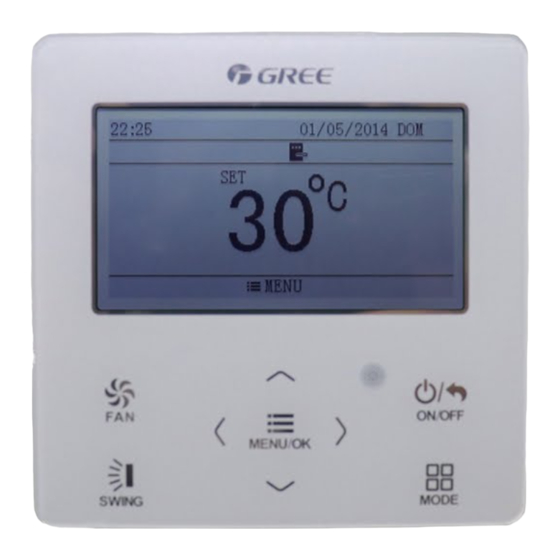
Wired Controller XE71-42/G 2 Display 2.1 Appearance Figure 2-1 Appearance of Wired Controller... -
Page 8: Instructions For Related Displayed Symbols
Wired Controller XE71-42/G 2.2 Instructions for Related Displayed Symbols Table 2.2.1 Instructions for Related Displayed Symbols Symbols Instructions Up and down swing function Left and right swing function Fresh air function Sleep function Auto mode Cooling mode Dry mode Fan mode... - Page 9 Wired Controller XE71-42/G Symbols Instructions Timer on status Gate card pulled-off status or nobody presented status Quiet function Function lock WiFi is turned on Independent swing is turned on Setback function is turned on Auxiliary heating status Display of set temperature: the temperature shown in the diagrams of this manual is in Fahrenheit scale(°F).
-
Page 10: Buttons
Wired Controller XE71-42/G 3 Buttons 3.1 Button Graphics Figure 3-1 Button Graphics... -
Page 11: Function Instructions Of Buttons
Wired Controller XE71-42/G 3.2 Function Instructions of Buttons Table 3.2.1 Function Instructions of Buttons Button name Button Function Set low speed, low-medium speed, medium speed, medium-high speed, high speed, turbo and auto speed (1) Set temperature ˄ (2) Set parameter ˅... - Page 12 Wired Controller XE71-42/G other functions can be set in corresponding submenu. Detailed menu structure is as shown in the Fig. as below. Figure 4-1 Menu Structure...
-
Page 13: On/Off
Wired Controller XE71-42/G 4.2 On/Off When the wired controller is on main page, press “ON/OFF” button to turn on the unit. Press “ON/OFF” button again to turn off the unit. The interfaces of On/Off status are shown in the Fig. as below. -
Page 14: Mode Setting
Wired Controller XE71-42/G Figure 4-3 Unit On Page 4.3 Mode Setting Under on status, press “MODE” button on the main page can set mode circularly as below. Figure 4-4 Mode Setting NOTES! If save function is turned on, auto mode is not available. -
Page 15: Temperature Setting
Wired Controller XE71-42/G 4.4 Temperature Setting Under on status, press “˄” or “˅” button on the main page to increase or decrease set temperature by 1°C (1°F); hold “˄” or “˅” button to increase or decrease set temperature by 1°C (1°F) every 0.3s. - Page 16 Wired Controller XE71-42/G Under on status, press “SWING” button to select up&down swing, then press “SWING” button, Up&down swing angle will be adjusted circularly as below: Figure 4-6 Up&Down Swing Select up&down swing and left&right swing through “˂” or “˃” button. When left&right swing is selected.
-
Page 17: Functions Setting
Wired Controller XE71-42/G 4.7 Functions Setting Press “MENU/OK” button on main page to enter main menu page. Press “˂” or “˃” button to select the function setting symbol. Then press “MENU/OK” button to enter user function setting page. Press “˄” or “˅” button to select specific function item. - Page 18 Wired Controller XE71-42/G Figure 4-8 Function Setting Function introduction is shown in the table as below. Table 4.7.1 Function Introduction Function Instruction Adjust indoor fresh air volume to improve air quality and Fresh air keep indoor air fresh. (The unit needs to be installed with a function new damper).
- Page 19 Wired Controller XE71-42/G Function Instruction I-Demand Unit will operate under save mode to save energy. function In the heating mode, when the user goes out, it is used to Holiday function maintain the indoor ambient temperature to ensure turbo heating when the user comes back.
- Page 20 Wired Controller XE71-42/G Function Instruction Low-temperature The unit runs the dry mode at a lower set temperature to drying function improve the drying capacity. After shutdown, the unit will automatically run to ensure that Setback function the indoor ambient temperature is within the set temperature range.
- Page 21 Wired Controller XE71-42/G Table 4.7.2 Mode Instruction Mode Instruction The unit continuously runs for 60min, and fresh air valve runs for 6 min. The unit continuously runs for 60min, and fresh air valve runs for 12 min. The unit continuously runs for 60min, and fresh air valve runs for 18 min.
- Page 22 Wired Controller XE71-42/G NOTES! Under fan or auto mode, sleep function is not available. Sleep function will be canceled when turning off the unit or switching mode. 4.7.3 Health Function Setting Under on status, after entering into user function page, press “˄” or “˅” button to select health function and press “˂”...
- Page 23 Wired Controller XE71-42/G I-DEMAND function will be cancelled while sleep function will be valid, and vice versa. 4.7.5 Holiday Function Setting Under on status, after entering into user function page, press “˄” or “˅” button to select holiday function option and press “˂” or “˃” button to turn on or turn off this function with auto saving.
- Page 24 Wired Controller XE71-42/G 4.7.7 Save Function Setting Under on status, after entering into user function page, press “˄” or “˅” button to select save function and press “˂” or “˃” button to turn on or turn off save function. Press “MENU/OK” button to enter save function setting page.
- Page 25 Wired Controller XE71-42/G auto saving. NOTE! This function can be set only in cooling and dry mode. 4.7.10 Filter Clean Reminder Setting After entering into user function page, press “˄” or “˅” button to select filter clean function and press “˂” or “˃” button to turn on or turn off this function. Press “MENU/OK”...
- Page 26 Wired Controller XE71-42/G 4.7.11 Quiet Function Setting Under on status, after entering into user function page, press “˄” or “˅” button to select quiet function and press “˂” or “˃” button to turn on or turn off this function with auto saving.
- Page 27 Wired Controller XE71-42/G Under on status, after entering into user function page, press “˄” or “˅” button to select low-temperature drying function and press “˂” or “˃” button to turn on or turn off this function with auto saving. NOTES! This function is only available in dry mode.
- Page 28 Wired Controller XE71-42/G temperature value. After that, press “MENU/OK” button to save setting. 4.7.17 Independent Swing Function Setting Under on status, after entering into user function page, press “˄” or “˅” button to select the independent swing function. Press “MENU/OK” button to enter into independent swing function setting page.
- Page 29 Wired Controller XE71-42/G selection is finished, press “MENU/OK” button to confirm it. If select to reset independent swing, the independent swing function of all air outlets will be turned off. Once it has entered into the independent swing setting list page, on/off status of independent swing function and swing mode for each air outlet can be viewed.
- Page 30 Wired Controller XE71-42/G NOTES! Once it has entered into the function, operation mode will be switched to the fan mode. Because the panel lifting is realized by changing the set temperature, if press “˄” or “˅” button continuously, it will reach to the limit value.
-
Page 31: Unit Status View
Wired Controller XE71-42/G which is a normal phenomenon. During cleaning, please make sure the room is well ventilated to avoid affecting the degree of comfort. When self-cleaning function is turned on, all buttons can’t be operated. If it needs to turn off the self-cleaning function compulsively, press any button on the homepage and a prompt message will appear, and then press “MENU/OK”... - Page 32 Wired Controller XE71-42/G Figure 4-10 Status View...
-
Page 33: Current Error View
Wired Controller XE71-42/G The following statuses can be viewed: if defrosting is operating; if auxiliary heating is operating; residual time of filter cleaning reminder; indoor ambient temperature; outdoor ambient temperature. NOTES! The residual time of filter cleaning reminder is valid only when the cleaning reminder function is turned on. - Page 34 Wired Controller XE71-42/G Figure 4-11 Current Error View...
- Page 35 Wired Controller XE71-42/G Table 4.9.1 Error Code List Error Code Error Compressor high-pressure protection Indoor anti-freeze protection Compressor low-pressure protection, refrigerant lack protection, refrigerant collection mode Compressor air discharge high-temperature protection Communication error Indoor fan error Water-full protection Indoor ambient temperature sensor error...
- Page 36 Wired Controller XE71-42/G Error Code Error Compressor overload protection Overload IPM protection DC fan error Driver out-of-step protection PFC protection Startup failure Compressor phase-sequence protection Power protection IDU and ODU unmatched or Controller unmatched 4–way valve switch-over error Driver reset protection...
- Page 37 Wired Controller XE71-42/G Error Code Error Driver current error Sensor connection protection Temperature drift protection Bus low-voltage protection Bus high-voltage protection Charging loop error Input voltage error Driver memory chip error ODU jumper cap error Phase-loss and anti-phase protection ODU error, for specific error please see the status of ODU indicator...
- Page 38 Wired Controller XE71-42/G Error Code Error High or low photovoltaic voltage protection Overcurrent protection at power grid side Voltage over/under frequency at power grid side Drive IPM module protection at power grid side Hardware overcurrent protection at power grid side...
- Page 39 Wired Controller XE71-42/G Error Code Error DC bus midpoint potential imbalance Insulated impedance protection Photovoltaic leakage current protection Phase-lacking protection at power grid side Indoor fan bus low-voltage protection Indoor fan bus high-voltage protection Indoor fan AC current protection Indoor fan IPM protection...
- Page 40 Wired Controller XE71-42/G Error Code Error Indoor fan driver module sensor error Indoor fan driver memory chip error Indoor fan charging loop error Indoor fan input voltage error Indoor fan electric box sensor error Indoor fan zero-crossing protection Suction temperature sensor error...
-
Page 41: Timer Setting
Wired Controller XE71-42/G Error Code Error Outdoor fan phase-sequence protection Outdoor fan driver reset protection Outdoor fan over-current protection Outdoor fan power protection Outdoor fan driver current error Outdoor fan driver out-of-step protection Master control and outdoor fan driver communication error... - Page 42 Wired Controller XE71-42/G setting page. Press “˄” or “˅” button to select one kind of timer. Press “˂” or “˃” button to turn on or turn off this timer. Please refer to the Fig. as below. Figure 4-12 Turn On or Turn Off Timer 4.10.1 One Time Clock Timer...
- Page 43 Wired Controller XE71-42/G Figure 4-13 One Time Clock Timer Press “˂” or “˃” button to select timer hour or minute and press “˄” or “˅” button to adjust time. Hold “˄” or “˅” button to increase or decrease time rapidly. Once setting is finished, press “MENU/OK”...
- Page 44 Wired Controller XE71-42/G cooling), set temperature in heating (it is valid only when the current mode is heating). Please refer to the Fig. as below. Figure 4-14 Daily Timer Setting After entering daily timer setting page, press “˂” or “˃” button to select setting item.
- Page 45 Wired Controller XE71-42/G Press “˂” or “˃” button to select the item to be set. Press “˄” or “˅” button to adjust the content. Press “MENU/OK” button to save setting. Please refer to the Fig. as below.
- Page 46 Wired Controller XE71-42/G...
- Page 47 Wired Controller XE71-42/G Figure 4-15 Weekly Timer Setting 4.10.4 Two Week Timer The user can set the everyday timer content for two weeks. In each day, the user can set eight segments of timer content. The unit will execute corresponding timer setting in two weeks.
- Page 48 Wired Controller XE71-42/G Figure 4-16 Setting of Current Week After entering two week timer menu page, press “˄” or “˅” button to select the two week schedule and then press “MENU/OK” button to enter two week timer programming. After entering two week timer setting page, press “˂” or “˃” button to select the day to be set.
- Page 49 Wired Controller XE71-42/G set simultaneously. If timer off in “x” hours and timer on in “y” hours are set simultaneously in unit on status, the unit will be off in “x” hours and then the unit will be turned on in “y” hours after timer off.
- Page 50 Wired Controller XE71-42/G Figure 4-18 Countdown Timer Off If timer function is turned on, the set hours will decrease as the unit operation time increases. In this case, residual hours can be viewed after entering timer setting page. This timer function will be executed for only once and then it will be cancelled automatically.
-
Page 51: Clock Setting
Wired Controller XE71-42/G 4.11 Clock Setting 4.11.1 Time Format Setting The user can set the time format in 12-hour system or 24-hour system. Select clock symbol in menu page and then press “MENU/OK” button to enter clock setting page. Press “˄” or “˅” button to select time format and then press “˂” or “˃” button to select 12-hour system or 24-hour system. - Page 52 Wired Controller XE71-42/G Press “˂” or “˃” button to select setting items: hour, minute, year, month, day; press “˄” or “˅” button to set the value and then press “MENU/OK” button to save setting. Please refer to the Fig. as below.
-
Page 53: Lock Setting
Wired Controller XE71-42/G Figure 4-20 Clock Setting 4.12 Lock Setting Select lock symbol in menu page and then press “MENU/OK” button to enter into the lock setting page. Press “˄” or “˅” button to select the item to be locked and then... - Page 54 Wired Controller XE71-42/G Figure 4-21 Lock Setting Items can be locked: ON/OFF, MODE, SET TEMPERATURE, FAN SPEED, KEY LOCK. Once locking is finished, the corresponding item cannot be set through buttons. If the keys are locked, all keys cannot be operated after returning to the main page.
-
Page 55: Installation Instructions
Wired Controller XE71-42/G 5 Installation Instructions 5.1 Parts and Dimension of Wired Controller Unit: mm Figure 5-1 Dimension of Wired Controller... -
Page 56: Installation Requirements
Wired Controller XE71-42/G Figure 5-2 Parts of Wired Controller Table 5.1.1 Standard Parts Panel of Tapping Soleplate of Name wired screw Screw M4×25 wired controller ST3.9×25 MA controller Quantity 5.2 Installation Requirements (1) Prohibit installing the wired controller at wet places. -
Page 57: Installation Methods
Wired Controller XE71-42/G 5.3 Installation Methods Figure 5-3 Installation Diagram for Wired Controller The above Fig. is the simple installation process of wired controller; please pay attention to the following items: (1) Before installation, please cut off the power for indoor unit. -
Page 58: Disassembly
Wired Controller XE71-42/G (2) Pull out the 2-core twisted pair wire from the installation hole on wall, and pull this wire through the “∩” hole at the rear side of the soleplate of wired controller (3) Stick the soleplate of wired controller on the wall and then use tapping screw ST3.9×25 MA or screw M4×25 to fix soleplate and installation hole on wall together.
Need help?
Do you have a question about the XE71-42/G and is the answer not in the manual?
Questions and answers