Table of Contents
Advertisement
Advertisement
Table of Contents

Related Manuals for Canon Inner Finisher-K1


Summary of Contents for Canon Inner Finisher-K1
- Page 1 Revision 3.0 Inner Finisher-K1 Service Manual...
- Page 2 When changes occur in applicable products or in the contents of this manual, Canon will release technical information as the need arises. In the event of major changes in the contents of this manual over a long or short period, Canon will issue a new edition of this manual.
- Page 3 Introduction Symbols Explanation Symbols Explanation Disconnect the connector. Connect the power cable. Connect the connector. Disconnect the power cable. Remove the cable/wire from the Turn on the power. cable guide or wire saddle. Install the cable/wire to the cable Turn off the power. guide or wire saddle.
-
Page 4: Table Of Contents
Contents Contents Safety Precautions....................1 Power Supply............................2 Notes Before Servicing........................2 Points to Note at Cleaning........................2 Notes On Assembly/Disassembly....................... 2 Notes on Assembly/Disassembly......................2 Points to Note when Tightening a Screw....................2 1. Product Overview.....................4 Features.............................. 5 Features...............................5 Specifications............................6 Finisher Unit............................6 Staple Unit............................7 Staple-free Staple Unit.......................... - Page 5 Contents Jam Detection.............................37 Power Supply............................ 39 Outline............................... 39 Protective Functions..........................39 Upgrading............................40 Upgrading............................40 3. Periodical Service..................41 Periodic Servicing Tasks........................42 4. Parts Replacement and Cleaning..............43 Removing this Machine........................44 Removing this Machine from the Host Machine..................44 List of Parts............................46 External Cover............................
- Page 6 Contents Alignment Position Adjustment of the Alignment Plate ................73 Adjusting the Processing Tray Area......................75 Adjusting the Paper Alignment......................75 Adjusting the Staple Position........................81 Adjustment when Replacing the Parts....................86 Handling Finisher Controller PCB Replacements...................86 Service Label.............................87 Back-up of Service Mode........................87 Service Label............................87 6.
-
Page 7: Safety Precautions
Safety Precautions Power Supply........2 Notes Before Servicing......2 Points to Note at Cleaning....2 Notes On Assembly/Disassembly..2... -
Page 8: Power Supply
Safety Precautions Power Supply CAUTION: 1. As a general rule, do not use extension cords. Using an extension cord may result in a fire or electrical shock. If an extension cord must be used, however, use one for local rated voltage and over, untie the cord binding, and insert the power plug completely into the extension cord outlet to ensure a firm connection between the power cord and the extension cord. - Page 9 Safety Precautions In the case of a screw hole with a triangle mark near it as shown in the figure below, strongly tightening the screw may damage or deform the screw hole. In the case of a screw hole with a triangle mark, take care not to apply too much force when tightening the screw. The recommended torque value is shown below as a reference value.
-
Page 10: Product Overview
Product Overview Features..........5 Specifications........6 Name of Parts........9... -
Page 11: Features
1. Product Overview Features Features • Compact, inner finisher compatible with color MFPs. • Manual stapling, which enables paper to be inserted into the slit on the inner finisher and stapled manually a copy at a time. • Staple-free stapling, which binds up to five sheets of paper without staples. •... -
Page 12: Specifications
1. Product Overview Specifications Finisher Unit Item Specifications Remarks Stack tray Delivery tray No.2 delivery tray (top of finisher) Stacking method Delivery tray: Tray shift No.2 delivery tray: Fixed Stacking orientation Face down Paper type Thin, plain, recycled, heavy, coated, transparency, label, bond, postcard, pre- punched, envelope, tracing paper Paper size Feed direction: 139.7 to 457.2 mm... -
Page 13: Staple Unit
1. Product Overview Item Specifications Remarks Mixed stacking ca- Mixed size Delivery tray • The stacking capacities pacity Height 26 mm or less (equivalent to 250 sheets) are estimates when con- No.2 delivery tray verting weight to number Height 5.2 mm or less (equivalent to 50 sheets) of 80 g/m sheets. -
Page 14: Staple-Free Staple Unit
1. Product Overview Front 1-point stapling (45 deg) Rear 1-point stapling (45 deg) Manual stapling 5.0 -/+ 2.0 mm 5.0 -/+ 2.0 mm 5.0 -/+ 2.0 mm Unit (mm) Center 2-point stapling Paper size Pitch A3, A4 83 -/+ 4.0 203 -/+4.0 5.0 -/+ 2.0 Alignment... -
Page 15: Name Of Parts
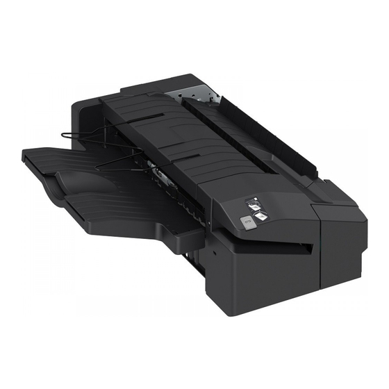
1. Product Overview Name of Parts Names of Parts Parts Name Parts Name No.2 Delivery Tray Staple Button Front Cover Delivery Tray (Stack Tray) Slit Auxiliary Tray Cross Section Parts Name Parts Name Paper Retainer Assist Guide Paddle Delivery Roller Return Belt Alignment Plate Inlet Roller... -
Page 16: Technical Explanation
Technical Explanation Basic Configuration......11 Controls..........12 Basic Operation........13 Feed Unit..........16 Processing Tray Unit......18 Stack Tray Unit........35 Jam Detection........37 Power Supply........39 Upgrading..........40... -
Page 17: Basic Configuration
2. Technical Explanation Basic Configuration Functional Configuration The components of this finisher are organized into 3 major blocks; feed unit, processing tray unit and stack tray unit. Stack Tray Unit Processing Tray Unit Feed Unit Overview of Electrical Circuitry This machine's sequence of the operation is controlled by the finisher controller PCB. The finisher controller PCB has the CPU(IC1), and the controller also controls the communication with the host machine in addition to controlling this machine's operation sequence. -
Page 18: Controls
2. Technical Explanation Controls Controls Item Reference Basic Operation Outline “Outline” on page 13 Initialization “Initialization” on page 15 Feed Unit Outline “Outline” on page 16 Feeding Paper to Processing Tray Unit “Feeding Paper to Processing Tray Unit” on page Processing Tray Unit Outline “Outline”... -
Page 19: Basic Operation
2. Technical Explanation Basic Operation Outline The finisher operates according to the commands that it receives from the host machine and ejects paper to the delivery tray. There are four paper delivery methods. • Non-sort stacking • Shift-sort stacking • Staple stacking •... - Page 20 2. Technical Explanation 3. The alignment plates are used to align paper in the width direction.(In the illustration below, paper is aligned with reference to the central reference position.) Rear Alignment Plate Front Alignment Plate 4. The operations described in steps (1) to (3) are repeated for each sheet to stack thesheets on the processing tray. 5.
-
Page 21: Initialization
2. Technical Explanation 6. After being shifted, the paper stack on the processing tray that has been stacked by the assist guide are delivered to the delivery tray. Assist Guide 7. After the paper stack has been delivered, the paper retainer holds down the stack in the delivery tray. Paper Retainer Initialization The finisher performs the following initialization operation depending on the status. -
Page 22: Feed Unit
2. Technical Explanation Feed Unit Outline The feed unit feeds the paper delivered from the host machine to the processing tray unit. A delivery sensor (PS1) is provided along the paper feed path in the feed unit to detect the paper feed state and jam. M3/4 Symbol Parts Name... - Page 23 2. Technical Explanation Paddle Unit Delivery Roller Inlet Roller Paddle Processing Tray Unit M1...
-
Page 24: Processing Tray Unit
2. Technical Explanation Processing Tray Unit Outline The processing tray unit aligns, shifts, and staples or staples without staples the delivered paper. Then the assist guide and assist claw deliver the paper onto the delivery tray. The names and functions of the components of the processing tray are as follows: Rear Alignment Plate Paper Retainer Paddle... - Page 25 2. Technical Explanation 1. After the delivery sensor (PS1) detects the trailing edge of the paper, the paddle motor (M10) runs to move the paddle unit down. The paddle driven by the feed motor (M1) delivers the paper toward the processing tray. After a given time elapses, the paddle unit is moved up.
-
Page 26: Alignment/Shifting Operation
2. Technical Explanation 3. The front/rear alignment motors (M3/M4) operate to move the front and rear alignment plates, thus aligning the paper in the width direction.(In the illustration below, aper is aligned with reference to the central reference position.) Operations described in steps (1) to (3) are repeated for each sheet. Rear Alignment Plate Front Alignment Plate Related service mode... - Page 27 2. Technical Explanation Rear Alignment Plate Rear Alignment Plate HP Sensor (PS5) Front Alignment Plate Rear Alignment Motor (M4) Front Alignment Plate Front Alignment Motor (M3) HP Sensor (PS4) The relationship between operation modes and alignment positions is summarized in the following table. Operation Paper Width Paper Length...
- Page 28 2. Technical Explanation • Adjustment of alignment position (LTR): SORTER > ADJUST > INF-ALG2 Related error code • E537-8001: Front alignment motor error • E537-8002: Front alignment motor error • E530-8001: Rear alignment motor error • E530-8002: Rear alignment motor error ■...
- Page 29 2. Technical Explanation 1. After the delivery sensor (PS1) detects the paper, the front and rear alignment plates move to the wait positions (paper width + 20 mm and paper width + 5 mm, respectively). Rear Alignment Plate End of Paper +5 mm Middle of Feeding Path End of Paper...
- Page 30 2. Technical Explanation 1. After the delivery sensor (PS1) detects the trailing edge of the paper, the front and rear alignment plates move to the wait positions. • Wait positions during front shift (front alignment plate position: paper width + 40 mm, rear alignment plate position: paper width + 5 mm) Rear Alignment Plate End of Paper...
- Page 31 2. Technical Explanation 2. Move the rear alignment plate to align the paper.(Do not move the front alignment plate.) NOTE: To improve the visibility when taking out the paper stack, move the rear alignment plate to the front even when shifting to the rear. •...
- Page 32 2. Technical Explanation 1. After the delivery sensor (PS1) detects the trailing edge of the paper, the front and rear alignment plates move to the wait positions. • Wait positions during front shift (front alignment plate position: paper width + +20 mm, rear alignment plate position: paper width + 5 mm) Rear Alignment Plate End of Paper...
- Page 33 2. Technical Explanation 2. Move the front and rear alignment plates to align the paper. • During front shift, move only the rear alignment plate.(Do not move the front alignment plate.) 5 mm Middle of Feeding Path 20 mm Front Alignment Position •...
- Page 34 2. Technical Explanation ■ Alignment Operation in Staple Mode 1. After the delivery sensor (PS1) detects the trailing edge of the paper, the front and rear alignment plates move to the wait positions.Explanation for 2-point stapling will be omitted because it is the same as the center alignment operation in Non- sort mode.
-
Page 35: Staple Operation
2. Technical Explanation Staple Operation ■ Outline In staple operation, the specified number of sheets of paper is stapled by the stapler unit. The staple position varies depending on the staple mode and paper size. The stapler unit's home position is detected by the stapler shift HP sensor (PS11). After power ON, the finisher controller PCB drives the stapler shift motor (M7) to return the stapler unit to the home position. -
Page 36: Staple-Free Staple Operation
2. Technical Explanation If the staple setting exceeds the stapling capacity (small size: 50sheets, large size: 30 sheets) that can be bound, divided delivery is performed. If the upper limit is exceeded, shift-sort mode is used for the second and subsequent copies. Example: Divided delivery for 51 A4 (80g/m ) sheets 50 sheets are delivered in a stack without stapling. - Page 37 2. Technical Explanation Clinch Motor Drive Detection Sensor (PS13) Clinch Motor (M9) Clinch Arm Rear Alignment Plate Assist Guide Clinch HP Sensor (PS15) Front Alignment Plate ■ Staple-Free Staple Unit When staple-free stapling is specified, the paper stack that is center-aligned by the processing tray is moved to the staple-free stapling position by the front alignment plate and assist guide.
-
Page 38: Stack Delivery Operation
2. Technical Explanation 5 sheets are delivered in a stack without stapling. The 6th sheet is delivered by itself. Related service mode • Adjustment of staple position for paper feed direction in the staple free stapling mode: SORTER > ADJUST > FR-STP-X •... -
Page 39: Paper Retainer Operation
2. Technical Explanation Paper type Paper size Paper Print mode Number of divided delivery sheets weight Transparency, label, 1-sided/2-sided 1 sheet postcard, envelope, tracing paper Recycled1/2/3, pre- Paper width: 210.0 mm to 1-sided/2-sided 2 sheets punched 297.0 mm Paper length: 173.4 mm to 431.8 mm Other than above 1-sided/2-sided... - Page 40 2. Technical Explanation Related error code • E516-0001: Paddle motor error • E516-0002: Paddle motor error...
-
Page 41: Stack Tray Unit
2. Technical Explanation Stack Tray Unit Stack Tray Shift Operation The paper delivered from the processing tray by the assist guide is then stacked on the stack tray. The stack tray is moved up and down by the stack tray shift motor (M6). Before start of printing, the tray shift motor (M6) is driven to move the stack tray up/down to the position where the stack tray paper height sensor (PS9) detects the stack tray top surface. -
Page 42: Stack Tray Paper Full Detection
2. Technical Explanation When foreign matter is detected, the finisher sends 1C40 (error avoidance jam; tray shift motor error) to the host machine. The host machine LUI displays a foreign matter check message. If foreign matter is detected again within a given time period, an error code (E540-8002) will be displayed. -
Page 43: Jam Detection
2. Technical Explanation Jam Detection Jam Detection The finisher is equipped with the following paper detection sensor to check whether paper is present and whether the stapler is operating normally. Further, it is equipped with the following switch to detect the open or closed state of the front cover. •... - Page 44 2. Technical Explanation Jam type Sensor Jam description Error avoidance jam Any of the following errors is detected during feeding operation. Assist motor error (E514) Paddle motor error (E516) Rear alignment motor error (E530) Stapler shift motor error (E532) Return belt motor error (E535) Front alignment motor error (E537) Tray shift motor error (E540) Paddle motor error (E577)
-
Page 45: Power Supply
2. Technical Explanation Power Supply Outline When the host machine is turned on, it supplies the finisher controller PCB with 24 VDC and 5 VDC. The 24 VDC power is used to drive the motors and the switches, while the 5 VDC power is for the sensors and the like. Finisher Controller PCB (PCB1) +3.3V +3.3VDC... -
Page 46: Upgrading
2. Technical Explanation Upgrading Upgrading When upgrading the firmware of the finisher controller PCB, upgrade from the host machine. (For details, see the service manual for the host machine.) -
Page 47: Periodical Service
Periodical Service Periodic Servicing Tasks.....42... -
Page 48: Periodic Servicing Tasks
3. Periodical Service Periodic Servicing Tasks The finisher does not have any items that need to be periodically serviced. -
Page 49: Parts Replacement And Cleaning
Parts Replacement and Cleaning Removing this Machine.......44 List of Parts......... 46 External Cover........51 Main Unit..........55 Motor........... 62 PCB.............64 Sensor..........65 Other Parts..........66... -
Page 50: Removing This Machine
4. Parts Replacement and Cleaning 4. Release the Latch [2], and then move the finisher Removing this Machine from the host machine. Removing this Machine from the Host Machine ■ Procedure 1. Open the Front Cover [1] of the Host Machine. 2. - Page 51 4. Parts Replacement and Cleaning 6. Remove the Connector [1]. 7. Hold the finisher as shown below, and then remove the finisher [1] from the host machine.
-
Page 52: List Of Parts
4. Parts Replacement and Cleaning List of Parts External Cover Parts Name Reference Front Cover Unit “Removing the Front Cover Unit” on page 51 Tray Guide Cover “Removing the Tray Guide Cover” on page 53 Delivery Tray “Removing the Delivery Tray” on page 51 “Installing the Delivery Tray”... -
Page 53: List Of Motors
4. Parts Replacement and Cleaning Parts Name Reference Upper Feed Guide Unit “Removing the Upper Feed Guide Unit” on page 55 Processing Tray Unit “Removing the Processing Tray Unit” on page 55 Parts Name Reference Stapler Unit “Removing the Stapler Unit” on page 60 Staple-free Staple Unit “Removing the Staple-free Staple Unit”... -
Page 54: List Of Sensors/Switches
4. Parts Replacement and Cleaning Parts Name Main Unit Reference Return Belt Motor Product Configuration Front Alignment Motor Processing Tray Unit Rear Alignment Motor Processing Tray Unit Assist Motor Processing Tray Unit “Removing the Assist Motor (M5)” on page 62 Tray Shift Motor Product Configuration Stapler Shift Motor... -
Page 55: List Of Pcbs
4. Parts Replacement and Cleaning Parts Name Main Unit Reference Rear Alignment Plate HP Sensor Processing Tray Unit Processing Tray Paper Sensor Processing Tray Unit Assist HP Sensor Processing Tray Unit Paper Fold HP Sensor Processing Tray Unit Stack Tray Paper Height Sensor Processing Tray Unit PS10 Stack Tray Lower Limit Sensor... -
Page 56: Other Parts
4. Parts Replacement and Cleaning Other Parts Parts Name Main Unit Reference Return Belt Unit Product Configuration “Removing the Return Belt Unit” on page 66... -
Page 57: External Cover
4. Parts Replacement and Cleaning External Cover Removing the Rear Cover ■ Preparation Removing the Front Cover 1. Remove this machine from the host machine. Unit “Removing this Machine” on page 44 ■ Preparation ■ Procedure 1. Remove the machine from the host machine. 1. -
Page 58: Installing The Delivery Tray
4. Parts Replacement and Cleaning CAUTION: Points to Note when Installing the Delivery Tray 1. Do not nip the Paper Fold [1] when the Delivery Tray [1] is installed. When attaching the Delivery Tray is difficult by the Paper Fold position, move the Tray Rack [A] to the bottom for ease of assembly. -
Page 59: Removing The Tray Guide Cover
4. Parts Replacement and Cleaning 2. When installing the Stack Tray, check that the 2 ■ Procedure Claws [2] and 2 Hooks [3] of the Stack Tray [1] is properly installed. If the installation fails, error; 1. Remove the Upper Stay [1]. E540-8001/8002 may occur at power ON. - Page 60 4. Parts Replacement and Cleaning CAUTION: Do not nip the Paper Fold [1] when the Tray Guide Cover is installed.
-
Page 61: Main Unit
4. Parts Replacement and Cleaning 2. Remove the 1 Clip [1] and 1 Bushing [2]. Main Unit Removing the Upper Feed Guide Unit ■ Preparation 1. Remove the machine from the host machine. “Removing this Machine from the Host Machine” on page 44 2. - Page 62 4. Parts Replacement and Cleaning ■ Procedure 1. Remove the Front Tray Rack [1] / Rear Tray Rack [2]. NOTE: How to assemble the Front Tray Rack and Rear Tray Rack 3. Remove the Tray Shift Motor Unit [1]. 1. Insert the Front Tray Rack [1] and Rear Tray Rack [2] •...
- Page 63 4. Parts Replacement and Cleaning 5. Remove the E-ring [1], and move the Gear [2], after 7. Remove the E-ring [1] and the Pully [2] and the Pin that remove the pin [3] and the Bushing [4] and the [3] and the Bushing [4]. Tray Drive Shaft [5].
- Page 64 4. Parts Replacement and Cleaning 9. Put through the Cables [1] at the hole [2]. CAUTION: Be sure to route the Cables [1] of the Processing Tray inside of the Cables [2] to cause abnormal noise by interfering with the tray guide cover.
- Page 65 4. Parts Replacement and Cleaning 10. Rotate the machine [1] as shown below, and remove the 2 Screws [2] of the Front/Rear Return Belt Guide. 14. Remove the Rear Plate [1]. • 2 Screws [2] 11. Return the machine to its original position. 15.
-
Page 66: Removing The Stapler Unit
4. Parts Replacement and Cleaning Removing the Stapler Unit ■ Preparation 1. Remove the machine from the host machine. “Removing this Machine” on page 44 2. Remove the Front Cover Unit.“Removing the Front Cover Unit” on page 51 ■ Procedure 1. - Page 67 4. Parts Replacement and Cleaning 2. Remove the Staple-free Staple Unit [1]. • 2 Screws [2] CAUTION: How to assemble the Staple-free Staple Unit When assembling, be sure to align the groove [1] of the Staple-free Staple Unit with the Stepped Screw [2]. ■...
-
Page 68: Motor
4. Parts Replacement and Cleaning Motor Removing the Assist Motor (M5) Removing the Stapler Shift ■ Procedure Motor (M7) 1. Remove the machine from the host machine. “Removing this Machine” on page 44 ■ Preparation 2. Remove the Front Cover Unit.“Removing the Front 1. - Page 69 4. Parts Replacement and Cleaning CAUTION: When reinstalling the Assist Motor Assembly, apply tension to the belt in the following procedures. 1. Loosen the Screw [1], and attach the Spring [2]. 2. Apply tension to the belt [4] retaining the plate end [3] by a hand and then tighten the screw [1].
-
Page 70: Pcb
4. Parts Replacement and Cleaning Removing the Finisher Controller PCB ■ Handling before replacement • When backup is possible 1. Before replacing the finisher controller PCB, back up the counter values of consumableparts and various adjustment values to the host machine using the host machine's service mode. -
Page 71: Sensor
4. Parts Replacement and Cleaning Sensor Removing the Delivery Sensor(PS1) ■ Preparation 1. Remove the machine from the host machine. “Removing this Machine” on page 44 2. Remove the Front Cover Unit.“Removing the Front Cover Unit” on page 51 3. Remove the Rear Cover.“Removing the Rear Cover”... -
Page 72: Other Parts
4. Parts Replacement and Cleaning Other Parts Removing the Return Belt Unit ■ Preparation 1. Remove the machine from the host machine. “Removing this Machine” on page 44 2. Remove the Front Cover Unit.“Removing the Front Cover Unit” on page 51 3. - Page 73 4. Parts Replacement and Cleaning 6. Remove the Front Return Belt Guide [1]. • 1 Boss [2] • 1 Clip [3] • 1 Bushing [4] 7. Remove the Return Belt Unit [1]. • 1 Clip [2] • 1 Bushing [3]...
-
Page 74: Adjustment
Adjustment Overview..........69 Basic Adjustment........ 71 Adjustment when Replacing the Parts ............86 Service Label........87... -
Page 75: Overview
5. Adjustment Overview Adjustment and Functional Setting in Service Mode ■ Adjustment For details, see the service manual for the host machine. Items Outline Use case SORTER > ADJUST > STP-2P Adjustment of 2-stapling position When the staples position in front/rear di- rection is displaced in the 2-stapling mode SORTER >... -
Page 76: Basic Adjustment Items
5. Adjustment Items Outline Use case SORTER > OPTION > TRY-PSTN To set the tray position after the com- Upon user's request (to improve pletion of job visibility of the delivered paper) SORTER > OPTION > PADL-TM *2 To set whether to extend paper pull- When paper pull-back failure oc- back time at 2-sided print. -
Page 77: Basic Adjustment
5. Adjustment Basic Adjustment Alignment Plate Right-Angle Adjustment When you remove or replace the alignment plate of the processing tray unit or when alignment errors occur, adjust the right-angle of the alignment plate. ■ Right Angle Adjustment of Alignment Plate <Use case>... - Page 78 5. Adjustment 2. Loosen the 2 fixing screws of the alignment plate (front and rear), adjust the alignment plate as follows, and then tighten the 2 screws. • Front alignment plate: Fit the leading edge to the paper. The trailing edge make space of 1mm or less. •...
-
Page 79: Alignment Position Adjustment Of The Alignment Plate
5. Adjustment 6. Fit the leading edge of the front alignment plate to paper, and confirm that a gap between the adjustment plate and the paper are 1mm or less at [A] portion. 10 mm Front Alignment Plate 1.0 mm or less Paper Alignment Position Adjustment of the Alignment Plate ■... - Page 80 5. Adjustment 3. Set A4 or LTR paper on the processing tray unit. 4. Fit the paper [1] to the leading edge [2] of the rear alignment plate. 5. Measure the gap [a] between the leading edge [3] of the front alignment plate and the edge of the paper. CAUTION: Because the front alignment plate is installed a bit tilting toward the delivery direction, set the paper to be fitted to the leading edge.
-
Page 81: Adjusting The Processing Tray Area
5. Adjustment Adjusting the Processing Tray Area In the case adjusting the processing tray area, adjust the paper alignment at first, and adjust the staple position. In the case adjusting the paper alignment, adjust skew and transport direction at first, and adjust front‐rear direction. Items Use case Refer to... - Page 82 5. Adjustment 1. Enter the following Service Mode. • Adjustment of alignment position (A4): SORTER > ADJUST > INF-ALG1 • Adjustment of alignment position (LTR): SORTER > ADJUST > INF-ALG2 2. Enter the setting value -50 (switch negative/positive by -/+ key) and press OK key. This operation stops the alignment plate at the current alignment position +5.0mm.
- Page 83 5. Adjustment 9. In case failure occurs again, repeat steps 1 and 8. 10. Remove paper on the processing tray. 11. Enter the values of service mode items recorded on the service label of the finisher rear cover. ■ Adjusting Center Alignment Standard Position <Use case>...
- Page 84 5. Adjustment ■ Right Angle Adjustment of Alignment Plate <Use case> • When remove or replace the alignment plate. • When the paper alignment position is displaced. Feed Direction Feed Direction <Procedure of adjustment> CAUTION: Perform the adjustment under either of the following states. •...
- Page 85 5. Adjustment 2. Loosen the 2 fixing screws of the alignment plate (front and rear), adjust the alignment plate as follows, and then tighten the 2 screws. • Front alignment plate: Fit the leading edge to the paper. The trailing edge make space of 1mm or less. •...
- Page 86 5. Adjustment 6. Fit the leading edge of the front alignment plate to paper, and confirm that a gap between the adjustment plate and the paper are 1mm or less at [A] portion. 10 mm Front Alignment Plate 1.0 mm or less Paper ■...
-
Page 87: Adjusting The Staple Position
5. Adjustment 1. Adjust return belt puressure by the following service mode. • SORTER > ADJUST > RBLT-PRS Return belt Feed Direction − + Adjustment range: -10 to 10 (Unit: 0.1 mm) As the value is changed by 1, the height of the return belt changes by height of 0.1 mm. +: Downward -: Upward Adjusting the Staple Position... - Page 88 5. Adjustment 1. Adjust the staple position by the following service modes. • Adjustment of front 1-stapling mode SORTER > ADJUST > INSTP-F1 • Adjustment of rear 1-stapling mode SORTER > ADJUST > INSTP-R1 • Adjustment of front 2-stapling mode SORTER >...
- Page 89 5. Adjustment 1. Mark the installation position of the stapler unit support plate. CAUTION: If returning its installation position to the original position, fix the stapler unit support plate by matching to the mark. Stapler Unit Mounting Plate 2. Loosen the two screws of the stapler unit support plate, adjust the stapler installation position by referring to the scale,and then tighten the screws.
- Page 90 5. Adjustment ■ Adjusting the Staple-Free Binding Position <Use case> • When the staple-free binding position in the staple-free binding mode. Feed Direction Feed Direction <Procedure of adjustment> NOTE: After the setting value is changed, write the changed value in the service label. 1.
- Page 91 5. Adjustment 2. Adjust the staple-free binding position by the following service modes. • SORTER > ADJUST > FR-STP-Y + − Feed Direction Adjustment range: -30 to 30 (Unit: 0.1mm) As the value is changed by 1, the staple position moves by 0.1 mm. +: Toward rear -: Toward front...
-
Page 92: Adjustment When Replacing The Parts
5. Adjustment Adjustment when Replacing the Parts Handling Finisher Controller PCB Replacements ■ Handling before replacement • When backup is possible 1. Before replacing the finisher controller PCB, back up the counter values of consumableparts and various adjustment values to the host machine using the host machine's service mode. SORTER >... -
Page 93: Service Label
5. Adjustment Service Label Back-up of Service Mode In factory setting, adjustments are made for each machine, and adjustment values are written in the service label. When you replaced the DC controller PCB, or executed the RAM clear function, adjustment values for ADJUST or OPTION return to default. -
Page 94: Troubleshooting
Troubleshooting Making Initial Checks......89 Processing Tray Area......90... -
Page 95: Making Initial Checks
6. Troubleshooting Making Initial Checks List of Initial Check Items Item Check Items Check Installation Environ- The value of power voltage is +/- 10% of the specified voltage. ment The machine is installed away from heat and moisture (near a faucet, water heater, or humidifier), cold place, source of fire or in an area exposed to dust. -
Page 96: Processing Tray Area
6. Troubleshooting Processing Tray Area Adjusting the Alignment and the Staple Position Alignment Position/Staple Position Adjustment 1.Adjusting Alignment 2.Adjusting Center Alignment 3.Right Angle Adjustment Front/Rear Misalignment of Paper Plate Position Standard Position of Alignment Plate direction 4.Adjusting the Return Feed Belt Pressure direction Staple... -
Page 97: Installation
Installation Checking Before Installation....92 Unpacking........... 94 Checking the Contents......95 Installation Procedure......96 Checking After Installation....104 Detaching from the Host Machine..105... -
Page 98: Checking Before Installation
7. Installation Checking Before Installation Checking the Installation Space Requirements for the installation place are given below. 100mm or more 500mm or more Check Items when Turning OFF the Main Power Check that the main power switch is OFF. 1. Turn OFF the main power switch of the Host Machine. 2. -
Page 99: Installation Outline Drawing
7. Installation Installation Outline Drawing Order of Installing this Equipment and Options When installing the following options at the same time, be sure to install them before installing this equipment. Refer to each installation procedure. • 3 Way Unit • Super G3 2nd Line Fax Board •... -
Page 100: Unpacking
7. Installation Unpacking Unpacking Procedure NOTE: This equipment is packed using tapes, fixings and cushioning materials to be protected vibration and shock during transportation. Be sure to remove all the fixing materials and the tapes before starting to install this equipment. It is a good idea to store away theremoved fixings and cushioning materials for possible relocation of this equipment, e.g., to new site or for repairs. -
Page 101: Checking The Contents
7. Installation Checking the Contents [1] Finisher X 1 [2] Finisher Stack Tray X 1 [3] Wire Sub Tray X 1 [4] Fixing Plate X 1 [5] Staple Cartridge X 1 [6] Coin Screw X 1 <Others> Including guides... -
Page 102: Installation Procedure
7. Installation Installation Procedure CAUTION: Check that the main power switch is OFF and the power plug is disconnected from the outlet. Preparation of the Host Machine CAUTION: When the Full Detection Flag has been installed already, be careful not to damage the Full Detection Flag. - Page 103 7. Installation Attach the Face Cover removed in step 2 to the Tray Guide supplied for Host Machine. NOTE: Put the Face Cover away in somewhere of the positions [2] to [4]. Do not put it away in the position [1] because it is easy to come off from the position [1].
- Page 104 7. Installation NOTE: Insert the flat head screwdriver in the gap between the Host Machine and the upper the protrusion of the Connector Cover. NOTE: The removed Connector Cover is used at late procedure. NOTE: Put the parts as shown in the figure.
-
Page 105: Installation Of This Equipment
7. Installation NOTE: Do not remove the Harness of connector (white) from the guide. (imageRUNNER ADVANCE C3500 series only.) Installation of this Equipment... - Page 106 7. Installation CAUTION: Check that the Stack Tray is properly installed. If the installation fails, error; E540-8001/8002 may occur at power ON. Hook Claw Claw Hook Hook Hook Claw Claw Claw Hook...
- Page 107 7. Installation CAUTION: • When the Full Detection Flag has been installed already, be careful not to damage the Full Detection Flag. • Be careful so that the Delivery Assembly Cover of the Host Machine is not damaged. Full Detection Flag Space NOTE: Secure enough space between this equipment and the...
- Page 108 7. Installation Attach the Connector Cover removed in Step7 of "Preparation of the Host Machine". NOTE: Push this Equipment toward the Inner Rear Cover of the Host Machine until it stops, and then slide this Equipment toward the paper delivery unit until the latch is surely engaged.
- Page 109 7. Installation...
-
Page 110: Checking After Installation
7. Installation Checking After Installation Confirm that the combination of the firmware Disposal Parts Check version for host machine and this equipment. Following disposal parts are remained after installation procedure. Check the paper feed and stapling operation and Reverse Trailing Edge Guide (Installed to 1pc. -
Page 111: Detaching From The Host Machine
7. Installation Detaching from the Host Machine Releasing the Latch CAUTION: Before detaching this Equipment from the Host Machine, be sure to check that the Host Machine has been turned off and its power plug has been disconnected from the outlet. -
Page 112: Appendices
APPENDICES Service Tools........107 General Circuit Diagram....108... -
Page 113: Service Tools
Service Tools Service Tools Solvents and Oils Name Uses Composition Remarks Alcohol Cleaning; e.g., Fluoride-family hydrocarbon • Do not bring near fire. plastic, rubber; external covers. Alcohol • Procure locally. Surface activating agent • Substitute: IPA (iso- Water propyl alcohol) Solvent Cleaning;... -
Page 114: General Circuit Diagram
General Circuit Diagram General Circuit Diagram General Circuit Diagram (1/1) Feed Motor Clinch Motor Stapler Motor 3 4 5 6 J2411 J2412 Front Cover Switch Clinch Motor 1 2 3 4 1 2 3 4 5 MSW1 Clinch HP Drive Detection U545 Delivery Sensor...
Need help?
Do you have a question about the Inner Finisher-K1 and is the answer not in the manual?
Questions and answers