
Related Manuals for Bolin Technology 1 Series


Summary of Contents for Bolin Technology 1 Series
- Page 1 1 Series 4K HDBaseT Zoom Camera USER MANUAL VERSION: FBC-4KHDB-M-02202021 FBC-1-4K12S-SMB © 2021 Bolin Technology...
-
Page 2: Table Of Contents
Contents IMPORTANT INFORMATION ..............................3 WHAT’S IN THE BOX ................................5 OVERVIEW .................................... 6 ..................................... 6 ODEL UMBERS FEATURES ....................................6 CAMERA DIAGRAMS ................................7 ......................................7 AMERA ................................... 8 ECEIVER ..................................9 EMOTE ONTROLLER ......................................10 OWER ..................................10 ABLE EQUIREMENTS .................................... -
Page 3: Important Information
Before operating the unit, please read this manual thoroughly and retain it for future reference. Copyright Copyright 2015-2021 Bolin Technology all rights reserved. No part of this manual may be copied, reproduced, translated, or distributed in any form or by any means without prior consent in writing from our company. - Page 4 Use of this document and the subsequent results shall be entirely on the user’s own responsibility. Safety Information WARNING! Installation and removal of the unit and its accessories must be carried out by qualified personnel. You must read all of the Safety Instructions supplied with your equipment before installation and operation.
-
Page 5: What's In The Box
WHAT’S IN THE BOX Camera: HDBaseT Receiver (Not included with the camera, order separately) Accessories (Optional) -
Page 6: Overview
Overview Model Numbers This user guide is suitable for the following models: • FBC-1-4K12S-SMB • BL-BR4K-1 (HDBaseT Receiver for HDBaseT built-in camera models, not included with the camera, order separately) Features • 1 Inch “Exmor R” CMOS sensor, Effective pixel number: 20.5 Megapixels •... -
Page 7: Camera Diagrams
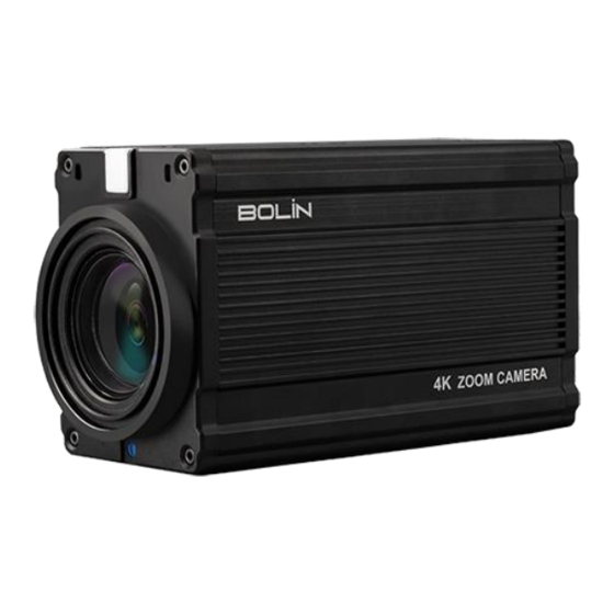
Camera Diagrams Camera 1. Built-in Audio Mics 2. Tally Light 3. IR Receiver 4. Built-in Audio Mics 5. Power Switch 6. 12V DC Power Port Connect the supplied DC power adaptor and cord with power port type: YC8-4pin 7. HDMI(4K) Video Output Port HDMI 1.4b 8. -
Page 8: Hdbaset Receiver
HDBaseT Receiver 18. LAN Port (RJ45, IP Pass-Thru) Connect network switch or router to this port for Dual Output HDMI+IP HDBaseT camera. NOTE: • This HDBaseT receiver is not an IP video encoder. The LAN Port is the IP video extension for the IP video output on the camera side. -
Page 9: Remote Controller
Remote Controller 1. MENU, on screen menu display ON/OFF 2. Camera IR ID Selector for Remote Control. 3. AI Features, available when AI button (13#) is pressed. (Not activated, for future use). 4. Positioning Function and Number Buttons • Preset Position Calling and Setting 5. -
Page 10: Power
Power • Use only the DC power adaptor (power port type: YC8-4pin) supplied with the unit. Do not use any other DC power adaptor. • Use POH Power Over HDBaseT to power up the camera. Use CAT5e/6 network cable connect the camera from HDBaseT port and the HDBaseT receiver to run distance up to 100 meters over one cable. -
Page 11: Audio In / Out
Audio In / Out • On real panel, a microphone or audio source can be connected to the audio LINE IN port, which feeds audio into the camera. Table: Audio input & output relationship Audio Input SDI Audio HDMI Audio HDBaseT Audio Output Embedded Embedded... -
Page 12: Obtain Video Signal
Obtain Video Signal HDMI 4K / HD Video signal 1. The camera video format is set to 1080P59.94 by default, so that you can have the video display on regular HD monitor/TV. Do not set camera video format to 4K resolution until you have a 4K monitor/TV ready for displaying. -
Page 13: Camera Control Methods And System Configurations
Information of the camera initial setting status will display for 5 seconds. Camera Status Info Display 1. Camera PELCO ID for RS-485 control PELCO ID VISCA ID 2. Camera VISCA ID for RS-422/232 control IR ADDRES 3. Camera ID for IR Remote Controller BAUD RATE 9600 4. -
Page 14: Control The Camera Using Hdbaset Receiver
Control the camera using HDBaseT Receiver Use one single CAT6 T-568B Standard Ethernet cable direct connect between the camera and the HDBaseT Receiver. HDBaseT carries up to 4K HDMI video signal, RS232/RS422/RS485 control signal, Audio, IR control signal, Power to the camera. -
Page 15: Use Rs-232 (Visca)
Use RS-232 (VISCA) You can use RS-232 port to connect to optional controllers, such as joystick control keyboard, control PC station, to operate the camera. To perform pan/tilt and zoom operations using the joystick of the control keyboard, and to perform the Preset operation using the control buttons. - Page 16 Use the adaptor cable RJ45 to RS232 8 pin Mini Din adaptor included to make RS232 connection for your control device. Use extension cables included RJ45 to RS422/232 Phoenix terminal contact adaptor to make RS232 connection for your control device.
-
Page 17: Use Rs-422(Visca)/Rs-485 (Pelco P/D)
10. Or you can use CAT5/6 network cable (T-568B standard pinout) to make RS232 connection by following the pin definition below: Use RS-422(VISCA)/RS-485 (PELCO P/D) You can use RS-422/485 port connect to optional controllers, such as joystick control keyboard, control PC station, to operate the camera. - Page 18 RS422 (VISCA) connection Set RS422 camera ID address (Default 1) in the camera OSD menu. Set Baud Rate (Default 9600) in the camera OSD menu to the same Baud Rate as the Baud Raye set on the keyboard you are using.
- Page 19 12. Or you can use CAT5/6 T-568B Standard Ethernet cable direct connect between the camera and the controller to make RS422 connection by following the pin definition below: 13. How to make RS422 Daisy Chain multiple camera connection with RS422 standard serial port controller:...
-
Page 20: Pelco P/D Keyboard Rs485 Connection
14. How to make RS422 Daisy Chain multiple camera connection using HDBaseT with RS422 standard serial port controller: PELCO P/D Keyboard RS485 Connection NOTE: Use RS422 ports for RS485 connection. Only use TX+ and TX- for RS485 connection. Set RS422 control method on Bottom Dip Switch. Set Baud Rate on Bottom Dip Switch to the same as Baud Rate setting on the keyboard you are using. - Page 21 Use extension cables included RJ45 to RS422 Phoenix connecter adaptor to make RS485 connection for your control device. 10. Or you can use CAT5/6 T-568B Standard Ethernet cable direct connect between the camera and the controller to make RS485 connection by following the pin definition below:...
- Page 22 11. How to make RS485 Daisy Chain multiple cameras connection with RS485 standard serial port controller: 12. How to make RS485 Daisy Chain multiple camera connection using HDBaseT with RS422 standard serial port controller:...
-
Page 23: How To Make The Connection With Bolin Products
Note For RS-232 VISCA control, this unit supports daisy chain connection for using multiple cameras. For control details, refer to Operating Instructions of control keyboard/station software. • You need to match the communication speed (Baud Rate) between the camera and the joystick controller. •... -
Page 24: Tally Light Gpi I/O Connection
Tally Light GPI I/O connection The camera is equipped with a Tally lamp that quickly distinguishes when the camera is in use. In order to use camera Tally Light function, you need a video switch and a keyboard (not included). GPI connection with RS422 VISCA control connection Cable Preparation 1. - Page 25 e. If switch to camera 2 on video switch, then camera 2 tally light will on and camera 1 tally light will off; 2. GPI I/O Output mode -Tally signal is sent by Keyboard Controller a. Connect camera with keyboard by standard RS-422 control cable; b.
-
Page 26: Adjusting And Setting With Menus
Adjusting and Setting with Menus About On-Screen Menus You can change various settings, such as shooting conditions and system setup of the camera, while observing menus displayed on a connected computer screen. This section explains how to read the on-screen menus before starting menu operations. The menu parameters may vary according to the different product model numbers. -
Page 27: Exposure Menu
EXPOSURE Menu The EXPOSURE menu is used to set the items related to exposure. MODE (Exposure Mode) EXPOSURE MENU FULL AUTO: The exposure is adjusted >EXPOSURE MODE FULL AUTO >WHITE BALANCE SLOWSHUTTER automatically using the sensitivity, electronic >PICTURE1 MAX SHUTTER 1/350 shutter speed, and iris. -
Page 28: White Balance Menu
EX-COMP (Exposure Compensation) When MODE is set to one of FULL AUTO, SHUTTER PRI or IRIS PRI, set this item to ON to enable exposure compensation. When you set EX-COMP to ON, LEVEL appears and you can select the exposure compensation level from the following: –10.5, –9, –7.5, –6, –4.5, –3, –1.5, 0, +1.5, +3, +4.5, +6, +7.5, +9, +10.5 If you set the level to 0, exposure compensation will be disabled. -
Page 29: Picture
NOTE: When you select the OPW (One Push White Balance) Perform the following operations: 1. Place an image of white subject (For example: A piece of white paper) in the center of the screen. 2. Press the HOME button of the infrared remote controller. The one-push white balance adjustment is activated. -
Page 30: Picture2
deterioration in resolution can be obtained because the digital zoom is not used. On the other hand, the correction effect by the image stabilizer function is maximized on the tele side, reducing the blur. NR (Noise Reduction): The NR function removes noise (both random and non-random) to provide clearer images. This function has six steps: levels 1 to 5, plus off. -
Page 31: Zoom Menu
VISIBILITY ENHANCER (VE) Depending on the imaging scene, the Visibility Enhancer function makes the darker part of a camera image brighter, and automatically correct brightness and contrast to show bright parts clearly. ZOOM Menu The ZOOM menu is used to select the zoom mode. DIGITAL ZOOM: OFF, ON, SRZ •... -
Page 32: System Menu
SYSTEM Menu PELCO ID When using RS485 (PELCO P/D) control, Set PELCO ID to the address that you want to control to. This value is from 000-255. VISCA ID When using RS422/ RS232 (VISCA) control, Set Camera VISCA ID to the address that you want to control to. This value is from 0-7. -
Page 33: Operation Using The Infrared Remote Controller
Operation Using the Infrared Remote Controller Pan/Tilt and Zoom Operation Panning and Tilting 1. Press the POWER switch. The camera will turn on and perform the pan/tilt reset operation automatically. 2. Press the arrow button to pan or tilt the camera. While checking the picture on the screen, press the desired arrow button. -
Page 34: Operating Multiple Cameras With Infrared Remote Controller
When the STANDBY lamp is blinking If the camera is moved forcibly, or a finger or other object interferes with camera movement, the camera may fail to memorize the pan/tilt position. Press the PAN-TILT RESET button to reset the pan/tilt position. Zooming Button (Slow Zoom) [T] - Zoom-IN and [W] - Zoom-OUT slowly Button (Fast Zoom) [T] - Zoom-IN and [W] - Zoom-OUT quickly... -
Page 35: Storing The Camera Settings In Memory - The Presetting Feature
Storing the Camera Settings in Memory — the Presetting Feature Memory (Preset) Using the preset function, 9 sets of camera shooting conditions can be stored and recalled. 9 sets of camera shooting conditions can be stored and recalled by using remote controller. Up to 128 presets via protocol programming. This function allows you to achieve the desired status instantly, even without adjusting the following items each time. - Page 36 Adjusting the camera Adjusting the camera, including camera image parameter (Gain, Color, Contrast, White Balance (Red & Blue), Black Level), camera speed (Pan/Tilt speed, zoom speed and preset speed), as well as Freeze, Back Light and One Push White Balance. Gain-Adjust Gain Press Gain button, the Gain button light will on, then press “+”...
- Page 37 AI Feature Mode This IR Remote Controller can be used for BOLIN AI (Auto Framing/Auto Tracking) camera, we can set this IR controller to AI mode, to set up AI feature quickly. AI Button: Press AI button, the IR controller will switch to AI mode. Zoom: AI Feature, it is available when AI button is pressed.
- Page 38 Changing Video Resolutions • Press and hold Fn button, then press the Resolution button to populate a menu where you can switch resolutions • Use the arrow keys to navigate • Press Home to select • Screen will show ‘CHANGING…” •...
-
Page 39: Menu Configuration
Menu Configuration The menus of the camera are configured as described below. Initial settings of each item are in bold. OSD Menu Configuration... -
Page 41: Dimension
Dimension Unit: mm Installation Rack mount on HDBaseT Secure the HDMI cable on the HDMI upholder. - Page 42 2082 TECHNOLOGY LLC BOLIN TECHNOLOGY...
Need help?
Do you have a question about the 1 Series and is the answer not in the manual?
Questions and answers