
Related Manuals for Axminster Trade AT2552BE


Summary of Contents for Axminster Trade AT2552BE
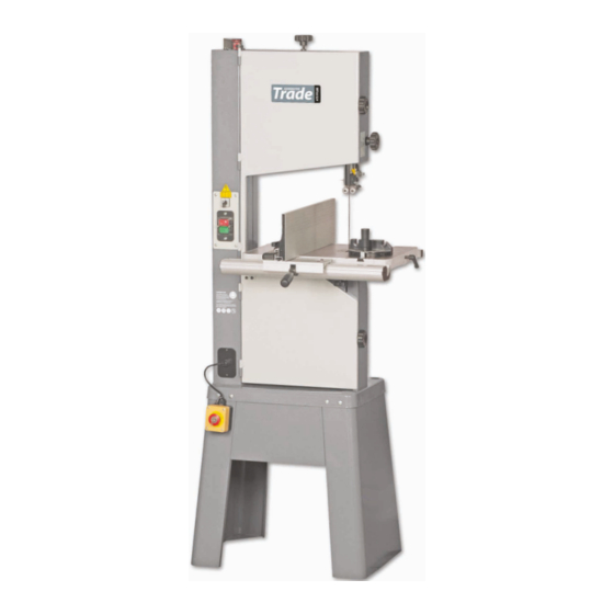
- Page 1 Code 700356 Original Instructions AT2552BE Bandsaw AT&M: 21/011/2018 BOOK REF: 105672...
- Page 2 Exploded Diagrams/Lists 31-32-33-34-35-36-37-38-39-40-41 Wiring Diagram Notes EU Declaration of Conformity Cert No: SBW-3501BS EU Declaration of Conformity Axminster Tools & Machinery Ltd This machine complies with the following directives: Axminster Devon EX13 5PH UK axminster.co.uk 2006/42/EC 2006/95/EC declares that the machinery described:- 06/42/EC - Annex I/05.2006...
- Page 3 What’s Included Quantity Item Model Number AT2552BE Industrial Bandsaw Bandsaw Blade 2,552mm (100.1/2”) long, mounted on saw but not tensioned. Cast Iron Table Stand Assembly: Stand Supports Stand Support Brackets Fence Assembly: Bags Comprising: Front Fence Rail with Scale Mitre Fence Rear Fence Guide Rail Clamping knobs with Fence...
- Page 4 What’s Included...
- Page 5 What’s Included...
-
Page 6: General Instructions For 230V Machines
General Instructions for 230V Machines The following will enable you to observe good working • Carry out a final check e.g. check the cutting tool practices, keep yourself and fellow workers safe and maintain is securely tightened in the machine and the correct your tools and equipment in good working order. - Page 7 Specification Code 700356 Model AT2552BE Rating Trade Power 750W 230V 1ph Blade Speed 800m/min Blade Length 2,552mm(100.1/2”) Blade Width Min/Max 3mm(1/8”)/19mm(3/4”) Max Width of Cut 340mm Max Depth of Cut 200mm Table Size 495 x 360mm Table Height on Stand 1,060mm Table Tilt -10°...
- Page 8 Main Assembly Step 2 Line up the remaining holes in the two parts of Mounting the Bandsaw the assembly and secure using the remaining M6 bolts, washers and nuts (20-22-25), securely tighten all fixing, see WARNING!! WHEN MOUNTING THE UNIT, figs 03-04.
-
Page 9: Cast Iron Table
Main Assembly Fig 13-14 Step 2 Line up the two elongated holes in the rear of the emergency stop housing with the two pre-drilled holes to the front of stand, insert one of the domed Phillips screw through the housing and while holding it in place screw on the M4 nut (21) and finger tighten. - Page 10 Main Assembly Step 2 Remove the table insert and table alignment pin Fig 20 and place safely aside, see figs 16-17. Lift the table (1), slide the blade through the table slot, see fig 18, line up the two threaded bolts to the underside of the table and lower them through the holes in the tilt quadrant assembly, see fig 19.
-
Page 11: Front Fence Rail With Scale 4
Main Assembly Fig 24 up the elongated holes in the front fence rail (4) with the pre-drilled holes to the front of the cast iron table (1), introduce the two M6x20mm bolts (12) through the fence rail and lightly tighten using the supplied spanner (22), see figs 27-28-29-30. Fig27-28-29-30 Checking both sides of the table are level Step 5 Replace the table insert by lining up the two pins in... -
Page 12: Fence
Main Assembly Fig 32-33-34 Fig 36 Adjustable guide rest Step 4 Locate the M8 nut (16), and screw it onto the thread 5mm Hex key of the M8 threaded lever (9) then screw the threaded lever (9) into the threaded hole in the clamp assembly (7) mechanism and tighten the nut with a spanner, see figs 37-38. - Page 13 Main Assembly Fig 39 Fig 43 Fig 40-41-42 Fig 44-45 Magnifying scale Step 7 Introduce the ‘T’ slot to the side of the fence (6) over the threaded ‘T’ slot insert (10) and slide on the fence until the fence (6) is flush with the end of the cast iron fence (7). Tighten the lift and shift handle (8), see figs 46-47-48.
- Page 14 Main Assembly/Machine Footprint NOTE: The fence (6) has two positions, vertical and horizontal for cutting narrow pieces, see fig 49-50-51. Fig 49-50-51 610mm Mitre Fence Assembly Locate the mitre fence (19) and slide the mitre fence into the table (1) ‘T’ slot, see fig 52. 610mm Fig 52...
- Page 15 Illustration and Parts Description Blade tensioning wheel Micro door switch Upper wheel door Upper door locking knob Upper blade guide adjusting wheel Main saw frame Upper blade guide and guard Selector switch Saw table ‘T’ slot for mitre fence ON/OFF buttons Mitre fence Fence guide rail Table alignment pin...
-
Page 16: Magnifying Glass 7
Illustration and Parts Description Key release emergency stop, press Upper door micro switch assembly the button to stop the bandsaw and turn the key to release it Electro-magnetic motor brake switch NVR switch On/Off buttons Scale magnifying glass Upper blade Brake OFF (1), Brake ON (0), Run (2) guide height scale and pointer Upper blade guide height... - Page 17 Illustration and Parts Description Upper wheel mounting Upper saw wheel Blade Table insert Saw table Drive pulley Lower saw wheel Continues Over..
- Page 18 Illustration and Parts Description Blade guide fore and aft adjusting knob (A), Rear thrust bearing adjusting knob (B) Blade (A), Tyre (B) Upper bearing blade guides (A), Rear thrust bearing (B) Blade tensioning mechanism and rear thrust bearing butterfly clamping screw (C) Lower bearing blade guide, butterfly clamp and adjusting knob (A), Drive pulley (A), Pulley belt (B) lower bearings guide guard (B) Rear thrust bearing, butterfly...
- Page 19 Illustration and Parts Description Quick release tensioning lever for changing the blade Blade tensioning scale Upper blade guide clamp Blade tracking control knob and locking knob Fence clamp lift and shift handle Rear fence guide rail Tilt quadrant assembly Dust extraction outlet Motor Continues Over..
- Page 20 Illustration and Parts Description Blade tensioning scale Quick release tensioning blade lever (A), Tracking control knob (B) and locking knob (C) Upper blade guide clamp Table tilt clamping knob (A), Table tilt scale (B) Dust extraction outlet and pointer with adjustment screw (C)
-
Page 21: Setting Up The Saw
Setting Up the Saw Fig 53 DISCONNECT THE SAW FROM THE MAINS SUPPLY! Tensioning and tracking the blade Make sure both top and bottom blade guides are well clear of the blade Open the front covers fully, giving good access to the top compartment of the saw and good visibility into the bottom compartment (see page 17). - Page 22 Setting Up the Saw Fig 57-58 Make sure the upper blade guide is raised as high as possible. Place a square on the table and move it up against the blade (behind the teeth), see fig 60. Check that the blade is perpendicular to the table. If it is not, try resetting the table.
- Page 23 Setting Up the Saw Fig 63 Setting the Blade Guides (above table) DISCONNECT THE SAW FROM THE MAINS SUPPLY! Pointer Lower the upper blade guide to approximately 1 1/2”(38mm) Scale above the table. Clamp in place. Loosen the butterfly screw (A), holding the guide assembly in place and adjust the fore and aft Adjusting screw position by turning the adjustment knob (B) so that the...
- Page 24 Setting Up the Saw Fig 70-71 Fig 73-74 2mm behind the blade Blade Guide bearings set to 0.5 thickness to the blade Thrust bearing Setting the Blade Guides (below table) IT MAY BE EASIER TO SET THE GUIDE BEARINGS IF THE CAST IRON TABLE (1) IS REMOVED, REFER TO MAIN ASSEMBLY INSTRUCTIONS.
- Page 25 Setting Up the Saw Fig 76-77 To adjust the lower thrust bearing, loosen the butterfly screw (D), see fig 80, turn the adjusting knob (E) to move the thrust bearing approximately 2mm behind the blade, see fig 82. Re-tighten the butterfly screw (D). When all adjustments have been made, recheck that when the blade is pressed back against the thrust bearing, both the upper and lower side guides are still behind the teeth of the...
- Page 26 Electro-magnetic Motor Brake Switch The electro-magnetic brake switch is located above the Fig 84 NVR switch asssembly and has three positions, see fig 83. • Position (0) engages the motor brake to prevent the bandsaw blade from moving and to isolate the bandsaw to prevent it from being started accidentally, see fig 84.
-
Page 27: Operating Instructions
Operating Instructions 1. Make sure you have read and fully understood the general 8. Make sure the blade is not in contact with the material when instructions and safety precautions that are printed in the you start the saw. Start the cutting operation. Do not try to cut preceding pages of this manual. -
Page 28: Changing The Saw Blade
Changing the Saw Blade Put the table back to the level position if it has been tilted. Open up all blade guides so that they are clear of the blade. Move the motor brake selector switch to position (1), see fig 85 Hold the blade approximately midway on either side of the and set the upper blade guide assembly approximately midway loop and feed it into the table slot. - Page 29 Changing the Saw Blade Ease the blade over the wheels and locate the blade in the Fig 91 Top of blade guide lined up with blade guides. Check that the blade is sitting approximately in the centre of the upper wheel the middle of the wheels and re-tension the blade by pushing the quick release lever forward.
- Page 30 Maintenance Clean out impacted ‘crud’ and saw dust Clean out impacted ‘crud’ and saw dust...
- Page 31 Exploded Diagrams/Lists Main Saw Assembly Continues Over..
-
Page 32: Spring Washers
Exploded Diagrams/Lists Item Part No Description Size Note 130075 BODY 130091 UPPER DOOR ASS’Y 130092 LOWER DOOR ASS’Y SR060200 SOCKET CAP BOLT M6x10 WS060000 SPRING WASHER SR059300 SOCKET CAP BOLT M5x12 130017 BIAS SHAFT 130018 BIAS SHAFT CLAMP SEAT 130020 ADJUST SHOES SM080400 SOCKET CAP BOLT... - Page 33 Exploded Diagrams/Lists 130031 BLADE COVER SH069200 HEX HEAD BOLT M6x8 WF061310 FLAT WASHER M6xφ13 SF069200 PAN HEAD BOLT W/FLANGE M6x8 130033 130044 FIXED RING SS050100 SET SCREW M5x5 130036 ADJUST SCREW 130022 SUPPORT SEAT 130048 SPRING 130023 INDICATOR 130019 FREE NUT 100152 LOCK KNOB M8x45...
- Page 34 Exploded Diagrams/Lists SF059300 PAN HEAD BOLT W/FLANGE M5x12 SR060400 SOCKET CAP BOLT M6x20 135041 KNOB NL061000 NYLON NUT 150031 SF059100 PAN HEAD BOLT W/FLANGE M5x6 130043 RIGHT COVER 995081 CLOSE-END CONNECTOR CE-1 130054 POINT SH069300 HEX HEAD BOLT M6x12 WF083030 FLAT WASHER M8x30 WS080000...
- Page 35 Exploded Diagrams/Lists SP040200 PAN HEAD BOLT M4x10 SP059300 PAN HEAD BOLT M5x12 WE050000 STAR WASHER (EXTERNAL) NH050800 IC130015 POWER CORD IM130005 MOTOR CORD SF059200 PAN HEAD BOLT W/FLANGE M5x8 136013 STRAIN RELIEF PG-13.5 136475 PLATE 136822 SWITCH PLATE 170245 SWITCH KJD-11-10D(JD3) 230V IC130011...
- Page 36 Exploded Diagrams/Lists Fence Assembly Part No Description Size SE049100 PAN HEAD SCREW M4x6 W/FLANGE 198018 FIXED BASE 198014 GUARD PIECE 198002 ADJUST BASE 200527 MOVING PLATE 198003 FIXED SHAFT 198016 PLUGGED 198005 SHAFT ST039300 TAPPING SCREW M3.5xl2 198006 SPRING WASHER LM000539 SCALE 198074...
-
Page 37: Mitre Fence
Exploded Diagrams/Lists Stand Assembly Item Part No Description Size Note 100144 STAND 100164 SIDE COVER SC089400 CRRIAGE BOLT M8x16 NF081300 SH069400 HEX HEAD BOLT M6x16 WF061310 FLAT WASHER M6x<p13 NF061000 SP049300 PAN HEAD BOLT W/FLANGE M4x12 NH040700 Mitre Fence Item Part No Description Size... - Page 38 Exploded Diagrams/Lists Single Speed Assembly Item Part No Description Size Note AB100251B LOWER WHEEL LJ021050 BELT 210J5 130027 MOTOR PULLEY SS060200 SET SCREW M6x10...
- Page 39 Exploded Diagrams/Lists Lower Wheel Assembly Item Part No Description Size 100250 LOWER WHEEL 150035 WHEEL TYRE BB620203 BALL BEARING 6202 RR350000 RETAINING RING 100274 PULLEY SJ060500 HEX SOCKET BOTTOM HEAD SCREW M6x25 WS060000 SPRING WASHER Upper Wheel Assembly Item Part No Descripution Size 100247...
- Page 40 Exploded Diagrams/Lists Upper Blade Guide Assembly Item Part No Descripution Size 150015 SPACING SLEEVE BB600002A BALL BEARING 6000ZZ 150213 CAM SHAFT 150013 THUMB SCREW M6xl6L 150207 SUPPORT BRACKET BB608002A BALL BEARING 608ZZ 141076 UPPER SUPPORT BRACKET POST SF069200 PAN HEAD FLANGE BOLT M6x8L 150010 ADJUST NUT...
- Page 41 Exploded Diagrams/Lists Lower Blade Guide Assembly Item Part No Description Size 150015 SPACING SLEEVE BB600002A BALL BEARING 6000ZZ 150213 CAM SHAFT 150013 THUMB SCREW M6xl6L 150207 SUPPORT BRACKET BB608002 BALL BEARING 608ZZ SE069200 PAN HEAD BOLT W/FLANGE M6x8L SR050400 HEX SOCKET BOLT M5x20L 150010 ADJUST NUT...
- Page 42 Wiring Diagram...
- Page 43 Notes...
- Page 44 The Axminster guarantee is available on Craft, Trade, Engineer, Air Tools & CNC Technology Series machines Buy with confidence from Axminster! So sure are we of the quality, we cover all parts and labour free of charge for three years! For more information visit axminster.co.uk/3years...
Need help?
Do you have a question about the Trade AT2552BE and is the answer not in the manual?
Questions and answers