Advertisement
Quick Links
Advertisement

Related Manuals for Axminster AT3352B


Summary of Contents for Axminster AT3352B
- Page 1 Code 104482 Original Instructions AT3352B Woodworking Bandsaw AT&M: 05/02/2019 BOOK REF : 105167...
- Page 2 Exploded Diagrams/Lists 22-23-24-25-26-27-28-29-30-31-32-33 Wiring Diagram Notes EU Declaration of Conformity Cert No: HW615E EU Declaration of Conformity Axminster Tools & Machinery Ltd This machine complies with the following directives: Axminster Devon EX13 5PH UK axminster.co.uk 2006/42/EC 06/42/EC - Annex I/05.2006...
- Page 3 What’s Included Quantity Item Part Model Number AT3352B Bandsaw Instruction Manual Tool Storage Bracket Dust Extraction Cover Floor Mounting Feet 12x60 Flat Washers Spring Washers Cap Screw 5x12 Hex Key 5mm Hex Key 4mm Hex Key 3mm Hex Key 2mm Please Note: Before discarding any packaging material check to make sure all terms are accounted for.
-
Page 4: General Instructions For 230V Machines
• Leave machine unplugged until work is about to commence. around you and USE YOUR COMMON SENSE. • Always disconnect by pulling on the plug body and not the cable. Specification Code 104482 Model AT3352B Power 2.2kW 230V 1ph Plug 3 pin 16 Amp Blade Speed 1050m//min Blade Length... - Page 5 Assembly Floor Mounting Feet Rip-Fence Assembly Remove the shipping pallet and place aside. Locate the four Follow the instructions below to assemble the fence. mounting feet (E) and with help mount them to each corner of Front fence rail the bandsaws base, see fig 01. Manoeuvre the bandsaw to the required position with plenty of space around the unit.
- Page 6 Assembly Tool Storage Bracket Fence clamp assembly Fence Clamp in Place Hex screw Flat washer Thin washer Storage bracket Fit the tool storage bracket to the side of the bandsaw, below the NVR switch assembly. Adjustable guide...
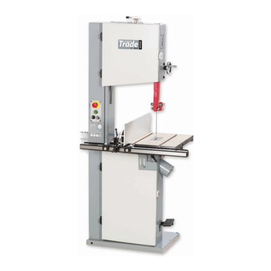
- Page 7 Illustration & Parts Description Upper Wheel Door NVR Switch with isolating Key Lock Tool Storage Bracket Main Frame Lower Wheel Door Blade Tensioning Lever Blade Tracking Window Upper Blade Guide adjusting Wheel Saw Table Dust Extraction Outlet...
- Page 8 Illustration & Parts Description Upper Door Lock Knob Upper Blade Guide Rip Fence Assembly Table Alignment Handle Table Tilt Operating Wheel Lower Wheel Foot Brake Tracking Control Knob with Locking Wheel Quick Release Tensioning Lever Table Support Damper Motor...
- Page 9 Illustration & Parts Description Table alignment handle Dust extraction outlet Emergency stop (A), ‘ON’ button (B), Selector switch (C), Power isolating key lock (D) Fence scale (E) and pointer (F) Table clamping handle (G), Table tilt scale (H), Scale pointer (I), Table tilt operating wheel (J)
- Page 10 Illustration & Parts Description Release Blade tensioning lever (K) Tension Tracking knob & locking wheel (L) Quick release tensioning lever (M), Upper guide adjusting wheel (N) Upper guide locking handle (O) Blade tension scale (P) Four fence alignment Hex screws (Q) adjust each Hex screw until Lower wheel foot brake the fence is perpendicular with the tables ‘T’...
- Page 11 Illustration & Parts Description Upper Blade Guide Lower Blade Guide Blade Guide Description Guide Holder Caphead screw Guide Bearing Adjusting knob Guide Bearings Lower Guide Bearing Clamping knob Upper Thrust Bearing Clamping Grub Screw Thrust Bearing Assembly Clamping Knob Thrust Bearing Adjusting Knob Guide Assembly Bracket Caphead Screws Lower Thrust Bearing Forward &...
- Page 12 Setup/Adjustment Fig 04-05 MOVE THE SELECTOR SWITCH TO ‘BRAKE OFF’ POSITION Tensioning and Tracking the Blade Make sure both top and bottom blade guides are clear of the blade Open the upper and lower wheel doors, giving good access to the saw wheels. To tracking the blade first adjust all guide bearings so they are clear of the blade, see fig 03.
- Page 13 Setup/Adjustment Fig 07 Power on Clamping handle Close the upper/lower doors, move the selector switch to the Fig 09 ‘RUN’ position and turn the ‘LOCK’ key to the power on position see fig 07. Stand clear and start the saw by pressing the ‘GREEN’ button.
- Page 14 Setup/Adjustment Setting the Fence MOVE THE SELECTOR SWITCH To make sure the guide fence is at 90˚ to the table, line up the TO ‘BRAKE OFF’ POSITION guide fence with the edge of the table’s ‘T’ slot, see fig 12. If you find that the fence is out of alignment follow the step below.
- Page 15 Setup/Adjustment Fig 22-23 Fig 18-19-20-21 0.5mm Loosen the clamping knob ( 7) and adjust the guide bearing approximately 0.5mm to the blade, see fig 22. NOTE: A sheet of A4 of photocopy paper is approximately 0.5mm thick. Re-tighten knob (7). Repeat for the other bearing. Close the blade guide access door (1).
- Page 16 Setup/Adjustment Fig 26-27-28 Guard clamp Thrust bearing Remove the lower blade guard (8) and loosen the clamp- Loosen the knob (11) and using the adjusting knob (12) ing knob (9). Using the adjusting knobs (10) adjust the lower position the thrust bearing 1mm behind the blade. guide bearings (B) so they are 2mm behind the gullets of the Make sure the groove is in line with the back of the blade, saw blade and 0.5mm on either side of the blade.
-
Page 17: Operating Instructions
Setup/Adjustment 45˚ Stop bolt -15˚ Stop screw Operating Instructions 1. Make sure you have read and fully understood the general 8. Make sure the blade is not in contact with the material instructions and safety precautions in the preceding pages when you start the saw. -
Page 18: Changing The Saw Blade
Changing the Saw Blade Upper door lock Lower door lock MOVE THE SELECTOR SWITCH TO ‘BRAKE OFF’ POSITION... - Page 19 Changing the Saw Blade Fig 31 Fig 34-35 Set the upper blade guide assembly approximately midway in the throat. Open the top and bottom covering doors and remove the table insert (B), see fig 31. Table slot Remove the table stabilising bolt (C) and release the blade tension by pushing the quick release lever up, see fig 32.
- Page 20 Changing the Saw Blade Turn the top wheel by hand to ensure the blade will not skip off the wheels and the blade is travelling in the blade guides. Re-fit the table stabilising bolt and table insert. Loosen the upper guide clamp (2) and position the assembly (3) so that the top of the blade guide is level with the centre of the top drive wheel, see fig 36-37.
- Page 21 Maintenance Clean out impacted ‘crud’ and saw dust Clean out impacted ‘crud’ and saw dust...
- Page 22 Exploded Diagrams/Lists...
- Page 23 Exploded Diagrams/Lists Name Description Lock Nut GB/T889.1 M8 Hex Socket Cap Screw GB/T70.1 M6X12 Washer HW616-03-21 Hinge HW616-01-73 Dust Guard HW616-01-76 Door HW615-01-90 Flat Washer GB/T97.1 6 Shockproof Soft Article 1.9 m Spring Washer GB/T 93 6 Position Indicator HW615-04-05 Cap Screw GB/T70.2 M6X16 Flat Washer...
- Page 24 Exploded Diagrams/Lists...
- Page 25 Exploded Diagrams/Lists Name Description Spring Bracket HW616-04-03B Knob HW615-04-40 Shaft HW616-04-02 Handle HW615-04-08 Lock Nut GB/T889.1 M10 Adjusting Nut HW616-04-23 Lock Nut GB/T6172.1 M12 Knob M8X35 Square Screw HW616-04-16B Flat Washer GB/T97.1 12 Rubber Belt HW615-02-06 Spring Washer GB/T93 12 Square Shaft HW616-04-20C Lock Nut...
- Page 26 Exploded Diagrams/Lists...
- Page 27 Exploded Diagrams/Lists Name Description Name Description Hex Socket Cap Screw GB/T70.3 M4X20 Lock Nut HWJ14-03-06 Set Screw GB/T77 M4X5 Flat Washer GB/T97.1 10 Insert HW616-03-07 Handle M10X25 Spring Sheet HW616-03-08 Locking Screw HW616-03-05B Flat Washer GB/T97.1 4 Degree Indicator HW616-03-19 Spring d=0.5, D=6.5, Cam Trunion...
- Page 28 Exploded Diagrams/Lists...
- Page 29 Exploded Diagrams/Lists Name Description Name Description Flat Washer GB/T97.1 8 Adjusting Screw HW616-05-03 Cap Screw GB/T70.1 M8X30 Spring d=l, D=10, m=6.5, Ho Brake Rubber Block HW616-06-03 Block HW616-05-02 Screw HW616-06-05 Support Block HW615-05-30 Brake Rod HW616-06-01 Set Screw GB/T77 M8X10 Spring d=2, D=12, m=30, Bracket...
- Page 30 Exploded Diagrams/Lists...
- Page 31 Exploded Diagrams/Lists Name Description Name Description Cap Screw GB/T70.2 M6X16 Cable Connector PG13.5 Spring Washer GB/T 93 6 Motor Label Flat Washer GB/T97.1 6 Motor 230V 50 Hz 3HP 1PH Circlip For Hole GB/T 893.1 22 Bearing 608-2RZ Hex Cap Bolt GB/T5783 M10X25 Bearing Bracket HWJ14-05-23...
- Page 32 Exploded Diagrams/Lists...
- Page 33 Exploded Diagrams/Lists Name Description Lock Nut GB/T889.1 M5 LOGO Upper Limit HW616-09-14 Switch Plate Switch Panel HW615-09-25 Cap Screw GB/T70.2 M5x16 Cap Screw GB/T70.2 M5xl2 Warning Label Switch Lock ZB2-BG2C Saw Blade HW615-08-03 Parameter Label Emergency Stop MPET4-10R-01 AC Contractor A16-30-10, 230V, 17A Button Grounding...
- Page 34 Exploded Diagrams/Lists Name Description Switch Panel HW615-09-25 Emergency Stop Button MPET4-10R-01 Start Button CPl-10G-10,Typec,5A Select Switch C3SS1-10B-20 Key Switch ZB2-BG2C...
- Page 35 Wiring Diagram...
- Page 36 The Axminster guarantee is available on Craft, Trade, Engineer, Air Tools & CNC Technology Series machines Buy with confidence from Axminster! So sure are we of the quality, we cover all parts and labour free of charge for three years! For more information visit axminster.co.uk/3years...
Need help?
Do you have a question about the AT3352B and is the answer not in the manual?
Questions and answers