Advertisement
Quick Links
Advertisement

Subscribe to Our Youtube Channel
Related Manuals for Axminster Trade AT3327B


Summary of Contents for Axminster Trade AT3327B
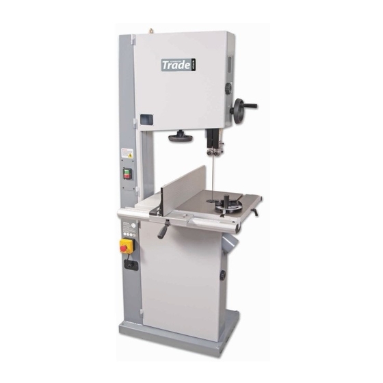
- Page 1 Code 501200 Original Instructions AT3327B Bandsaw AT&M: 31/07/2018 BOOK REF : 508307...
- Page 2 Maintenance Exploded Diagrams/Lists 28-29-30-31-32-33-34 Wiring Diagram EU Declaration of Conformity Cert No: SBW-430 EU Declaration of Conformity Axminster Tools & Machinery Ltd This machine complies with the following directives: Axminster Devon EX13 5PH UK axminster.co.uk 2006/42/EC 06/42/EC - Annex I/05.2006...
- Page 3 What’s Included Quantity Item Model Number AT3327B Bandsaw Bandsaw Blade 3,327mm (131”) long, mounted on saw but not tensioned. Cast Iron Table Fence Assembly Comprising: Table Extension Comprising: Front Fence Rail with Scale Extension Table Rear Fence Guide Rail M8 x 20mm Bolts Fence M8 Washers Fence Clamp Assembly with...
- Page 4 What’s Included...
- Page 5 What’s Included...
- Page 6 General Instructions for 230V Machines The following will enable you to observe good working • Carry out a final check e.g. check the cutting tool practices, keep yourself and fellow workers safe and is securely tightened in the machine and the correct maintain your tools and equipment in good working speed and function set.
- Page 7 Specification Code 501200 Model AT3327B Rating Trade Power 1,500W 230V 16A Blade Speed 390 & 840m/min Blade Length 3,327mm(131”) Blade Width Min/Max 3mm(1/8”) 25mm(1”) Max Width of Cut 410mm Max Depth of Cut 300mm Max Width of Cut with Fence 370mm Table Size 600 x 445mm...
- Page 8 Main Assembly Locate the cast iron table (1), table alignment pin (21), the Fig 06 four M8 x16mm bolts (24), M8x90mm bolt and nut (25), M8 washers and spring washers (26-27). Tilt quadrant Step 1 Locate the threaded bolt/nut (25), screw the nut onto the thread then screw the bolt into the pre-drilled hole in the bandsaw frame behind the tilt quadrant, see fig 03.
- Page 9 Main Assembly Fig 12 Fig 15-16 Step 4 Locate the table alignment pin (21), place a straight edge or 90˚ square across the table’s slot and introduce the tapered alignment pin into the tapered hole to the front of the table, this will align both sides of the table, see figs 13-14.
- Page 10 Main Assembly Step 3 Replace the table insert by lining up the two pins in the insert with the machined holes in the recess to the centre of the cast iron table. Push firmly down, see figs 19-20. Fig 19-20 Insert pin Machined hole Table recess...
- Page 11 Main Assembly Step 3 Fit the fence clamp assembly (5) over the front Step 5 Slide the fence assembly (5) until its up against fence rail (2) and lower the rear of the clamp assembly so the blade and press down the locking lever (7), see fig 32. the adjustable guide rests on top of the rear guide rail (3), Look at the magnifying glass to check it’s set to ‘0’...
- Page 12 Main Assembly Step 6 Locate the fence (4), M8 lift and shift handle (6), M8 NOTE: The fence (4) has two positions, vertical and large washer (11) and threaded ‘T’ slot insert (8), see fig 36. horizontal for cutting narrow pieces, see figs 42-43-44. Place the large washer over the thread of the lift and shift Fig 42-43-44 handle (6), see fig 37, introduce the handle through the...
-
Page 13: Fig
Main Assembly Blade Guide & Guard Height Operating Wheel Locate the operating wheel (20) and 5mm Hex key (23). Loosen the caphead screw on the hand wheel and slide it onto the shaft. Re-tighten the caphead screw, see figs 46-47. Fig 46-47 Caphead screw Shaft... - Page 14 Illustration and Parts Description Eye bolt lifting ring Blade tracking window Upper wheel door Upper door locking knob Upper blade guide adjusting wheel Wheel tensioning window Upper blade guide and guard Blade tensioning wheel Saw table ‘T’ slot for mitre fence ON/OFF buttons Mitre fence Extension table...
- Page 15 Illustration and Parts Description Emergency stop, press to instantly On/Off button Eye bolt lifting ring stop the bandsaw Fence clamp assembly (5), Mitre fence (19), Fence rail with scale (2) Scale magnifying glass Upper blade guide height Table levelling stop bolt Table insert scale and pointer...
- Page 16 Illustration and Parts Description Micro door switch Upper wheel mounting Upper saw wheel Wheel tension pointer Table insert Saw table Lower saw wheel Drive pulley Dust extraction outlet...
- Page 17 Illustration and Parts Description Wheel tension scale and pointer Two position drive pulley Upper bearing blade guides (A), Blade guide adjusting knob (B), Blade guide Blade tensioning spring fore and aft clamping screw (C) Lower bearing blade guides (A), Blade guide adjusting knob (B), Blade guide Upper blade thrust bearing (A) fore and aft clamping screw (C), Rear thrust bearing (D) and adjusting screw (B)
- Page 18 Illustration and Parts Description Upper blade guide clamp Quick release tensioning lever for changing the blade Blade tensioning wheel Extension table Rear fence guide rail Tilt quadrant assembly Dust extraction outlet Motor...
- Page 19 Illustration and Parts Description Motor locking handle (A), Motor repositioning handle (B) Quick release tensioning blade lever (A), Upper blade guide clamping knob (B), Tracking control knob & locking handle (C) Blade tensioning wheel Tilt quadrant clamping handle (A), Table adjusting handle (B), Tilt quadrant Tilt quadrant scale pointer (A) scale (C), Lower thrust bearing adjusting knob (D) and adjusting screw (B)
-
Page 20: Fig 50
Setting Up the Saw Fig 48-49 DISCONNECT THE SAW FROM THE MAINS SUPPLY! Blade Tensioning and tracking the blade Make sure both top and bottom blade guides are well clear of the blade Open the front covers fully, giving good access to the top compartment of the saw and good visibility into the bottom compartment (see page 16). -
Page 21: Fig 52
Setting Up the Saw Fig 52 Fig 55-56 Motor locking handle Tilt quadrant clamping handle DISCONNECT THE SAW FROM THE MAINS SUPPLY! Checking the table is square Loosen the clamping handle beneath the table, clamp- ing the tilt mechanism. Turn the tilt quadrant adjusting handle until the table is hard against its stop. - Page 22 Setting Up the Saw of the side guide bearings are approximately 2 mm Setting the Fence behind the gullets of the saw blade. Re-tighten the Hex screw, see fig 62. Loosen the Hex screw (B) that clamps To make sure the guide fence is at 90˚ line up the guide the rear thrust bearing in position and adjust the thrust fence with the edge of the table’s ‘T’...
- Page 23 Setting Up the Saw Fig 64-65 Fig 67-68 2mm behind the blade adjusting knob (E) to move the thrust bearing Setting the Blade Guides (below table) approximately 2mm behind the blade, see fig 67-68. Re-tighten the Hex screw (D), see fig 66. When all Beneath the table loosen the Hex screw (C) holding the adjustments have been made, recheck that when the lower blade guide assembly in place and position so...
- Page 24 Operating Instructions 4. Check, especially on site, that there are no foreign material to the saw line) along the saw line so that you objects e.g. old nails, screws, small stones etc can discard the off cuts as you progress down the saw embedded in the material you are about to cut.
- Page 25 Changing the Saw Blade Fig 71 Fig 73-74 Tension released Quick release blade lever Lower finger guard WARNING! BE VERY CAUTIOUS WHEN YOU ‘UNFOLD’ THE BLADE; IT TENDS TO ‘SPRING’ OPEN, BLADE AND TEETH GOING EVERYWHERE. Also check that the blade did not “unfold” inside out. i.e.
- Page 26 Changing the Blade Speed Fig 77-78 DISCONNECT THE SAW FROM THE MAINS SUPPLY! Motor locking handle The bandsaw drive pulley has two speed positions, see fig 80. To change the speed to either 390 or 840m/minute, follow the instructions below. Open the upper and lower doors, see fig 76.
- Page 27 Maintenance Daily Monthly • Keep the machine clean. • Open the lower and upper door and check the condition of the tyres and the drive belt, see figs 81-82-83. • Check the saw blade for missing teeth and cracks, see fig 81. •...
- Page 28 Exploded Diagrams/Lists...
- Page 29 Exploded Diagrams/Lists Part No Description Size SR060200 HEX SOCKET BOLT M6x10 WF040808 FLAT WASHER M4x08 135004 LIMPID PIECE NH040700 SF040700 PAN HEAD BOLT W/ M4x35 FLANGE SP040200 PAN HEAD SCREW M4x8 136457 DOOR LATCH SWITCH AZD-S11 995101 RING (ASM) 135128 MACHINE BODY 136201 UPPER WHEEL COVER...
- Page 30 Exploded Diagrams/Lists WS100000 SPRING WASHER SR060400 HEX SOCKET BOLT M6x20 WF102325 FLAT WASHER M10xɸ23 SJ080400 HEX SOCKET BOTTOM M8x20 HEAD SCREW WF081820 FLAT WASHER M8xɸ18 WS080000 SPRING WASHER WS080000 SPRING WASHER AB135050 GUIDE BRACKET (ASM) SH089400 HEX HEAD BOLT M8x16 AB198101 MITER GAUGE ASS’Y 135019...
- Page 31 Exploded Diagrams/Lists Fence Assembly Part No Description Size SE049100 PAN HEAD BOLR W/ M4x6 FLANGE 198018 FIXED BASE 198014 GUARD PIECE 198002 ADJUST BASE 200527 MOVING PLATE 198003 FIXED SHAFT 198016 PLUGGED 198005 SHAFT ST039300 TAPPING SCREW M3.5xl2 198006 SPRING WASHER LM000539 SCALE 198074...
- Page 32 Exploded Diagrams/Lists Guide Bracket Assembly Part No Description Size 135050 GUIDE BRACKET SS050100 SET BOLT M5x5 135033 WORM CYLINDER SR069400 HEX SOCKET BOLT M6xl6 135062 FIXED PLATE SP040200 PAN HEAD BOLT M4xl0 135049 GEAR NH040700 016320 FIXED BOLT 135029 RACK 135046 COVER 135047...
- Page 33 Exploded Diagrams/Lists Trunnion Support Bracket Part No Description Size WS080000 SPRING WASHER 135045 ADJUSTING BLOCK NL081300 NYLON NUT NH061000 SR061000 HEX HEAD BOLT M6x50 SR060400 HEX HEAD BOLT M6x20 135009 ADJUSTING BAR SP049100 PAN HEAD BOLT M4x6 135122 LEFT COVER SC081600 CARRIAGE BOLT M8x80...
- Page 34 Exploded Diagrams/Lists Mitre Fence Assembly Part No Description Size 198101 GUIDE BAR 198102 GUIDE PIECE SN069200 COUNTER SUNK BOLT M6x6 198103 POINTER SF059200 PAN HEAD BOLT W/FLANGE M5x8 198107 STEEL PIN ɸ6,5x10 198106 MITRE GAUGE BODY 198104 NYLON WASHER 198105 HANDLE Low Blade Guide Support Part No...
- Page 35 Wiring Diagram...
- Page 36 The Axminster guarantee is available on Craft, Trade, Engineer, Air Tools & CNC Technology Series machines Buy with confidence from Axminster! So sure are we of the quality, we cover all parts and labour free of charge for three years! For more information visit axminster.co.uk/3years...
Need help?
Do you have a question about the Trade AT3327B and is the answer not in the manual?
Questions and answers