Table of Contents
Advertisement
Quick Links
Advertisement
Table of Contents

Related Manuals for Axminster PROFESSIONAL AP2920B


Summary of Contents for Axminster PROFESSIONAL AP2920B
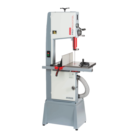
- Page 1 Code 108517 Original Instructions AP2920B Bandsaw AT: 17/10/2022 BOOK VERSION: 01...
-
Page 2: Table Of Contents
INDEX OF CONTENTS What’s In The Box 02-03 Anatomy 04-05 Safety Assembly 07-08-09-10 Set Up: Blade Tension 10-11 Bade Tracking 11-12 Setting Upper and Lower Blade Guides Thrust Bearing, Upper and Lower 12-13 Aligning the Table to the Blade Squaring the Table to the Blade Aligning the Fence to the Blade 14-15 Setting Fence Scale... -
Page 3: What's In The Box
WHAT’S IN THE BOX Fig C Tool Kit and Stand Fixing Bolts Fig E Fig D Dust Outlet Screws Fig G Table Dust Outlet, Hose Ring Clips, Table Insert and Blade Guide Rise and Fall Handwheel Fig F Cast Iron Table with Fence Rail Fig I Extraction Hose Fig H... -
Page 4: Anatomy
ANATOMY Blade tensioning wheel Blade tracking window Upper door locking knob Tensioning lever Push stick Wheel tensioning Upper blade guide window adjusting wheel Upper blade guide and guard Fence Upper blade guide ON/OFF buttons Mitre fence Cast iron table Table alignment pin Fence guide rail Fence clamp handle Dust extraction hose... - Page 5 ANATOMY Upper wheel door Upper saw wheel Blade tension pointer Saw blade Lower saw wheel Lower wheel door Micro door switch Drive pulley Tensioning lever Table tilt assembly Upper blade Tracking Tracking Dust extraction outlet Motor guide clamp control knob control lock...
-
Page 6: Safety
SAFETY The following is a list of safety precautions you must consider when using a bandsaw: ALWAYS REMEMBER TO DISCONNECT THE POWER TO THE BANDSAW WHEN MAKING REPAIRS OR ADJUSTING BLADES AND GUARDS. ALWAYS REMEMBER TO READ THROUGH THE MACHINE INSTRUCTIONS SUPPLIED. •... -
Page 7: Assembly
ASSEMBLY Fig 04-05 Stand Assembly 1. Fix the adjustable feet to each stand end panel, (fig 01). Fig 01 2. Fix the stand side panels to the end panels using the eight bolts, washer and nuts, (fig 02-05). Fig 02-03 Continues over... - Page 8 ASSEMBLY Fig 09 Attaching Stand to Bandsaw 1. Lay the bandsaw on its back to attached the stand assembly to bandsaw with the four stand Hex bolts and washers, (fig 06-07-08). Fig 06-07-08 3. Attach the dust outlet below the table with the four screws provided, (fig 10).
- Page 9 ASSEMBLY 5. Line-up the holes to the underside of the cast iron Fig 16-17-18 table with the ones in the trunnions and secure in place with four button head Hex bolts/washers, (fig 13-14). Fig 13-14 9. Locate the Rise and Full handle wheel, loosen the two grub screws around the mounting boss.
-
Page 10: Set Up
ASSEMBLY 10. Find the threaded hole to the side of the bandsaws column. Locate the push stick holding screw and screw it into the column, hook the push stick over the screw, (fig 21-22). Fig 21-22 SET UP Blade Tension •... -
Page 11: Bade Tracking
SET UP Fig 27 Fig 29-30-31 Blade Tracking Blade approximately centred DISCONNECT THE MACHINE FROM THE MAINS SUPPLY. • If the blade tends to shift to one side or the other of the wheel, slight adjustment will need to be •... -
Page 12: Setting Upper And Lower Blade Guides
SET UP Fig 33 Fig 35 Gullet Thumb Screw Approx. • IMPORTANT: This adjustment is sensitive; perform it in small increments and give the blade time to react to the changes, as you continue to rotate the Guide wheel. Bearing •... -
Page 13: Aligning The Table To The Blade
SET UP • Loosen thumb screw and turn knob to move the thrust bearing in or out until the bearing is approximately 1mm behind the blade, tighten thumb screw, (fig 37). Fig 37 Gullet Rear Thrust • If the mitre slot is not aligned with the blade, Bearing slightly loosen the four screws holding the trunnions to the table, (fig 40). -
Page 14: Squaring The Table To The Blade
SET UP Squaring the Table to the Blade DISCONNECT THE MACHINE FROM THE MAINS SUPPLY. • Loosen table locking knobs and tilt table to the left (down flat) until it rests against the table stop screw (fig 42). • Use a square placed on the table and against the left hand side of the blade (fig 43) verify that the table is 90 degrees to the blade. -
Page 15: Setting Fence Scale
SET UP Setting Fence Scale - Once the table and fence are squared and aligned you can attach the self adhesive scale to the fence rail. • Attach the fence to the fence rail and slide it over to lightly touch the blade, ensure that the blade to fence contact is very light - do not deflect the blade. -
Page 16: Mitre Fence
SET UP / GENERAL USE / OPERATION to gain understanding and knowledge of bandsaw Mitre Fence operations. • Slide the mitre fence into the slot around half way along the table, (fig 56). Firstly ensure that you have the right blade fitted for the intended cut - see the blade selection guide on •... -
Page 17: General Use / Operation
GENERAL USE / OPERATION • Turn on the bandsaw and allow a few seconds for the machine to reach full speed. • Whenever possible, use a push stick, hold-down, jig, or similar device while feeding timber, to prevent your hands getting too close to the blade, (fig 62-63). Fig 62-63 Tips: •... - Page 18 GENERAL USE / OPERATION Ripping cuts Crosscutting • Crosscutting is cutting across the grain of the Ripping is cutting lengthwise down the workpiece, and with the grain. Always use a push stick or similar timber, usually whilst using the mitre gauge to feed safety device when ripping narrow pieces.
-
Page 19: Blade Types
Axcaliber bandsaw blades are manufactured at not exceed 50mm. When cutting metals reduce the Axminster using advanced CNC machining, high speed as much as possible especially when cutting precision digital measuring equipment and ferrous metals or cast iron. - Page 20 BLADE TYPES The regular, or triangular, tooth form is provided on blades with 10 or more teeth per inch where, because of the reduced material removal, there is less need for waste storage. Premium Bandsaw Blades Ground Tooth Bandsaw Blades •Premium blades made from M42 with 8% cobalt.
-
Page 21: Blade Change
BLADE CHANGE Fig 77-78 DISCONNECT THE MACHINE FROM THE MAINS SUPPLY. Removing Blade • Open the doors • Adjust the upper blade guide set so that it is around half way down, (fig 74). • Remove the lower blade guards and open up/back off all blade guides so that they are clear of the blade, (fig 75-76). - Page 22 BLADE CHANGE Fig 81-82 Fig 86 Fig 87 • Clean crud from the tyres and remove any small off cuts that may be around the bottom blade guide set, (fig 83-84). • Use the blade selection guide on pages 17-18 to ensure that you have the right blade for the job! Fig 83-84 •...
-
Page 23: Troubleshooting
TROUBLESHOOTING Bandsaws are relatively simple machines and with all machinery regular servicing (preventative maintenance) is essential to get the best from your saw. “My bandsaw slows down ‘My bandsaw won’t cut straight” when cutting” • This is the most common question •... -
Page 24: Exploded Diagram/Parts Lists
EXPLODED DIAGRAM/PARTS LISTS (MJ3435-A) - Page 25 EXPLODED DIAGRAM/PARTS LISTS (MJ3435-A) Description Blade guard Sight glass Adjustable cushion B Conjoined door Adjustable cushion A Wood insert Hex socket pan head screw M4x8 Lower wheel Protection board Saw blade Gear box cover Upper wheel Hex socket cap head bolt M8x16 Drive belt Steel Plate Locking knob...
- Page 26 EXPLODED DIAGRAM/PARTS LISTS (MJ3435-A) Hex socket cap head bolt M6X20 Pointer Tension shaft Protection board U bracket Cross recessed pan head screw M4X10 Nut board Hex nut M4 Spring Hex nut M6 Lifting eccentric Door shaft Blade tension shaft Door lock knob Quick tension shaft Bearing nut Eccentric base...
- Page 27 EXPLODED DIAGRAM/PARTS LISTS (MJ3435-B) Continues over...
- Page 28 EXPLODED DIAGRAM/PARTS LISTS (MJ3435-B) Description Locking handle Washer 5mm Hex nut M8 Cross recessed pan head screw M5X8 Locking eccentric cam Big washer 8mm Spacer Self-locking nut M8 Cross recessed countersunk screw M4X6 Hex socket set screw M6X70 Wave washer Gear handle Spacer Nut M8...
-
Page 29: Wiring Diagram
EXPLODED DIAGRAM/PARTS LISTS (MJ3435-C) Description Mitre gauge guide rod Cross recessed countersunk screw Rail washer Hexagon socket set screws M6X12 Hex socket pan head screw M6X20 Hex socket set screw M6X6 Mitre gauge base Scale Stop pin Block indicator Spring washer 5mm Stop spring Hex socket cap head bolt M5X12 Mitre gauge knob... -
Page 30: Declaration Of Conformity
UK DECLARATION OF CONFORMITY ‘original’ Product model: AP2920B Bandsaw Name and address of the manufacturer: Axminster Tool Centre Ltd, Unit 10 Weycroft Avenue, Axminster, Devon EX13 5PH, United Kingdom This declaration of conformity is issued under the sole responsibility of the manufacturer. - Page 31 EC DECLARATION OF CONFORMITY ‘original’ Product model: AP2920B Name and address of the manufacturer: Axminster Tool Centre Ltd, Unit 10 Weycroft Avenue, Axminster, Devon EX13 5PH, United Kingdom This declaration of conformity is issued under the sole responsibility of the manufacturer.
- Page 32 The packaging is suitable for recycling. Please dispose of it in a responsible manner. EU Countries Only Do not dispose of electric tools together with household waste material. By law they must be collected and recycled separately. Axminster Tools, Axminster Devon EX13 5PH axminstertools.com...
Need help?
Do you have a question about the PROFESSIONAL AP2920B and is the answer not in the manual?
Questions and answers