
Summary of Contents for Lighting Controls Blue Box LT Series
- Page 1 ® THE BLUE BOX ™ OPERATION & MAINTENANCE MANUAL Lighting Control & Design ® 905 Allen Ave, Glendale CA 91201 Tel: 800-345-4448 www.lightingcontrols.com •...
-
Page 3: Table Of Contents
THE BLUE BOX LT OPERATION & MAINTENANCE MANUAL TABLE OF CONTENTS Overview . . . . . . . . . . . . . . . . . . . . . . . . . . . . . . . . . . . . . . . . . . . . . . . . . . . . . . . . . . . . . . . . . . . . . . . . . .5 Gr1404LT / Gr1408LT Drawings &... - Page 4 THE BLUE BOX LT OPERATION & MAINTENANCE MANUAL TABLE OF CONTENTS (Continued) Time Schedule Programming Examples . . . . . . . . . . . . . . . . . . . . . . . . . . . . . . . . . . . . . . . . . . . . . . . . . . . . . . . . . . . 88 Exercise #1- Contact Closure Device Controlling 4 Relays .
-
Page 5: Overview
® THE BLUE BOX ™ OVERVIEW Lighting Control & Design ® 905 Allen Ave, Glendale CA 91201 Tel: 800-345-4448 www.lightingcontrols.com •... - Page 6 THE BLUE BOX LT OVERVIEW TABLE OF CONTENTS Gr1404LT / Gr1408LT Drawings & Details . . . . . . . . . . . . . . . . . . . . . . . . . . . . . . . . . . . . . . . . . . . . . . . . . . . . . . . . . . 7 Relay Overview .
-
Page 7: Gr1404Lt / Gr1408Lt Drawings & Details
. . It lists out all of the Scroll and Tab to access control features for en- digital lighting controls devices, where they are tire system (Master only) . and what they do . (see System Start-Up Guide Door pocket contains the following documenta- for more information . - Page 8 THE BLUE BOX LT OVERVIEW low voltage only line voltage only GR1404/08 LT (WHITE DOOR OPEN) Screw fastener secures hinged Control Panel 32-channel, 365-day astronomical clock with Door (Master only) . Scroll and Tab to access control features for en- White door provides barrier between human tire system (Master only) .
- Page 9 THE BLUE BOX LT OVERVIEW GR1404/08 SLAvE PANEL RELAY CONTROL CARD GR1404/08 MASTER PANEL RELAY CONTROL CARD Relay Drivers . Opto-isolated to prevent line volt- Terminator pins . Add terminator here if this is the age back-feed and to help prevent RF and EMF first or last item on a bus (follow the “System noise interference .
-
Page 10: Relay Overview
THE BLUE BOX LT OVERVIEW To optional To optional BLUE BOX LT 1404/1408 Modem DI Card master panels INTERNAL SCHEMATIC only 3#18 AWG . Supplies power from trans- former to relay control card . 14 conductor ribbon cable: carries control signal between DTC and relay control card (master panel only) . -
Page 11: Gr1416Lt Drawings & Details
THE BLUE BOX LT OVERVIEW GR1416LT DRAWINGS & DETAILS GR1416 LT (FRONT DOOR OPEN) Screw fastener secures hinged Control Panel Door (Master only) . Hinged Door Panel provides a barrier between Control Interface and High Voltage connections beneath (Master only) . NEMA 1 surface mount enclosure with hinged door and key lock;... - Page 12 THE BLUE BOX LT OVERVIEW GR1416 LT (WHITE DOOR OPEN) Screw fastener secures hinged Control Panel SnapLink relays, Normally-Closed (NC) . Status ™ Door (Master only) . LED: ON when relay is OFF (NC) . Hinged Door Panel provides a barrier between DTC Clock / Display &...
- Page 13 THE BLUE BOX LT OVERVIEW GR1416 LT SLAvE PANEL RELAY CONTROL CARD GR1416 LT MASTER PANEL RELAY CONTROL CARD Relay Drivers connect to Smacker Strip . Relay Terminator pins . Add terminator here if this is drivers will close latching relays upon loss of an end-of-bus panel (per “System Start-Up &...
- Page 14 THE BLUE BOX LT OVERVIEW GR1416 LT (DOOR OPEN) INTERNAL SCHEMATIC 3#18 AWG . Supplies power from transformer Terminator/terminator pins to terminate bus line . to relay control card . external connections 14 conductor ribbon cable: carries control signal 4#24 flat cable from modem to analog phone between DTC and relay control card (master jack .
-
Page 15: Introduction To The Blue Box Lt ™ Series
THE BLUE BOX LT OVERVIEW INTRODUCTION TO THE BLUE BOX LT SERIES ™ The only panel you will ever need for small to medium projects - quicker to install than traditional lighting contactors and much easier to configure . The Blue Box LT Series is UL Listed and complies with every energy code in the USA . -
Page 16: The Blue Box Lt
THE BLUE BOX LT OVERVIEW THE BLUE BOX LT vS. LIGHTING CONTACTORS ™ SMART RELAY PANEL Outdoor Photocell The Blue Box LT Series is the only panel you will ever ™ need for small to medium projects . Breaker Panel It is quicker to install than traditional lighting contactors as well as more flexible . -
Page 17: Build Your System In 3 Steps
THE BLUE BOX LT OVERVIEW BUILD YOUR SYSTEM IN 3 STEPS Every system must have a Master Panel which contains the clock and photocell inputs and connections for the optional modem . STEP 1: MASTER PANEL How many circuits (relays) do you need to control? (See pgs . -
Page 18: Enclosure Sizes
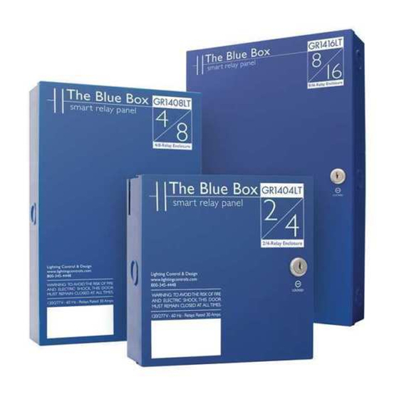
THE BLUE BOX LT OVERVIEW 3 ENCLOSURE SIzES DESIGNING WITH LIMITED SPACE? Gr1404LT The Blue Box LT Series comes pre-assembled and ready ™ • Shipped with 2 or 4 relays for installation in three compact enclosure sizes! • Master or slave configuration This 100% digital panel can be programmed to operate •... -
Page 19: Panel Configurations
THE BLUE BOX LT OVERVIEW 2 PANEL CONFIGURATIONS MASTER RELAY PANEL Master relay Panel Each system needs one master panel equipped with: DTC Modem for remote pro- gramming clock/programmer . Program schedules, switches and pho- tocells for multiple panels . Optional Hand/Auto Switch DTC clock/programmer •... -
Page 20: Most Popular Accessories
THE BLUE BOX LT OVERVIEW MOST POPULAR ACCESSORIES These represent the most popular LC&D accessories . For a complete list of accessories refer to the LC&D Catalog . Product: Description: Digital Outdoor Photocell (PCO): Connects to the master panel . Recommended for stormy regions (where it may darken early) to supplement the astronomical clock . - Page 21 THE BLUE BOX LT OVERVIEW The accessories below may not be available as a stocking product, but can be ordered . Product: Description: SwitchBolt: One or two vandal resistance buttons per gang . Switches can be mounted out- doors or almost any location . Product Code: SB-1 or 2 Link-To PC/Ethernet: Connect multiple computers to the GR 2400 system from any RS232, USB port or an ethernet network connection .
-
Page 22: Applications
THE BLUE BOX LT OVERVIEW APPLICATIONS See how easy it is to design and install the Blue Box LT in ™ different applications . We stand behind each of our prod- ucts with a 3 year warranty . SMALL PARkING LOT (SINGLE CONTROL PANEL) Select a master panel with the correct number of relays . -
Page 23: Warehouse (Multiple Control Panels)
THE BLUE BOX LT OVERVIEW APPLICATIONS (Continued) How Does the Blue Box LT Series Stack-up? In a na- ™ tionwide survey of Electrical Contractors, the cost to purchase and field-assemble lighting contactor panels was compared to the cost of the Blue Box LT Series . -
Page 24: Blue Box Technical Support
THE BLUE BOX LT OVERVIEW BLUE BOX TECHNICAL SUPPORT AFTER-MARkET SUPPORT The Blue Box ™ LT Series comes with LC&D’s top-notch customer support and, when connected to a phone line, includes free lifetime dial-up programming . Make changes to the Blue Box LT Series remotely (with ™... -
Page 25: Maintenance & Troubleshooting
MAINTENANCE & TROUBLESHOOTING MAINTENANCE & TROUBLESHOOTING Making Up Cat . 5 with RJ45 Connectors Adding a New Device Parts Replacement Guide Hardware Troubleshooting... -
Page 27: Making Up Cat . 5 Cable With Rj45 Connectors
® THE BLUE BOX ™ MAKING UP CAT. 5 CABLE WITH RJ45 CONNECTORS ® Lighting Control & Design 905 Allen Ave, Glendale CA 91201 Tel: 800-345-4448 www.lightingcontrols.com •... - Page 28 28 THE BLUE BOX LT MAKING UP CAT. 5 CABLE WITH RJ45 CONNECTORS TABLE OF CONTENTS introduction . . . . . . . . . . . . . . . . . . . . . . . . . . . . . . . . . . . . . . . . . . . . . . . . . . . . . . . . . . . . . . . . . . . . . . . . . . . . . . . . . . . . . . . 29 Ethernet Network .
-
Page 29: Introduction
THE BLUE BOX LT MAKING UP CAT. 5 CABLE WITH RJ45 CONNECTORS 29 INTRODUCTION All Lighting Control & Design systems use Cat . 5 cable with sistent quality in the Cat . 5 cable or crimp will not severely RJ45 connectors to network devices . While both our sys- impact this network’s stability . -
Page 30: The Gr 2400 Bus And Rs485 Communications Protocol
30 THE BLUE BOX LT MAKING UP CAT. 5 CABLE WITH RJ45 CONNECTORS INTRODUCTION (Continued) THE GR 2400 BUS AND RS485 Though a single imperfection may only slow down the COMMUNICATIONS PROTOCOL communication by a small margin it gets multiplied up over the length of the chain . -
Page 31: Cable And Crimping Quality
THE BLUE BOX LT MAKING UP CAT. 5 CABLE WITH RJ45 CONNECTORS 31 CABLE AND CRIMPING qUALITY THE IMPORTANCE OF A PROPER CRIMP direction and create multiple echo effects . This results in an “unstable bus” because these reflections or echoes Imperfections in a crimp adds a resistive and capacitive load make it difficult for our devices to receive data . -
Page 32: The Ideal Scene: Professionally Made Commercial Cables
32 THE BLUE BOX LT MAKING UP CAT. 5 CABLE WITH RJ45 CONNECTORS CABLE AND CRIMPING qUALITY (Continued) THE IDEAL SCENE: PROFESSIONALLY MADE Stranded wire does not fatigue as easily and break . Solid wire is usually used as “building wire . ” The reason being COMMERCIAL CABLES that it used to be cheaper and is not usually flexed after Common attributes of commercially made cables include:... -
Page 33: Reasons Why It's Hard To Make Good Crimps On Rj45S
THE BLUE BOX LT MAKING UP CAT. 5 CABLE WITH RJ45 CONNECTORS 33 REASONS WHY IT’S HARD TO MAkE GOOD CRIMPS ON Rj45s There are two components needed to crimp a Cat . 5 cable: a “crimper” and a “RJ45 modular connector . ” A crimper is the tool used to make a crimp and seal the cable to the connector . -
Page 34: The Right Modular Connector
34 THE BLUE BOX LT MAKING UP CAT. 5 CABLE WITH RJ45 CONNECTORS REASONS WHY IT’S HARD TO MAkE GOOD CRIMPS ON Rj45S (Continued) expensive, solidly made crimping tools did not make good Care must be taken to crimps . The best and recommended crimper is provided prevent any excess wire in the LC&D Crimping Kit . -
Page 35: How To Make Proper Crimps
THE BLUE BOX LT MAKING UP CAT. 5 CABLE WITH RJ45 CONNECTORS 35 HOW TO MAkE PROPER CRIMPS SEqUENCE OF ACTIONS Always use STRANDED cable! Only use “EZ-RJ45” brand connectors! Proper preparation of the wires is very important . Our kit comes with a wire stripper and cutter that is separate from the crimper (Figure 1 . - Page 36 36 THE BLUE BOX LT MAKING UP CAT. 5 CABLE WITH RJ45 CONNECTORS HOW TO MAkE PROPER CRIMPS (Continued) sure the locking prongs are facing down . Make sure that j) Assemble the other end the same way for a straight the insulation is well under the strain relief and that the through cable .
-
Page 37: Miscellaneous Information
THE BLUE BOX LT MAKING UP CAT. 5 CABLE WITH RJ45 CONNECTORS 37 MISCELLANEOUS INFORMATION Our cables are made up as “Straight Through” cables . The connectors at each end look identical . Notice that the green pair straddles the blue while the orange and brown take up the edges . -
Page 38: Summary
38 THE BLUE BOX LT MAKING UP CAT. 5 CABLE WITH RJ45 CONNECTORS MISCELLANEOUS INFORMATION (Continued) LC&D ships all relay panels with caps for the RJ45 connec- When you crimp an RJ45, always crimp it down multi- ple times to ensure properly aligned and evenly seated tors to get rid of the possibility of contamination . -
Page 39: Adding A New Device
® THE BLUE BOX ™ AddING A NEW dEVICE INSTRUCTIONS: STEP 1: STEP 5: Install new devices and note down their serial numbers on Verify proper connections and cabling for the entire bus using the “System Device Schedule” in the Master Panel (Refer to the Hardware Activation Tests . - Page 40 THE BLUE BOX LT ADDING A NEW DEVICE LOW vOLTAGE CABLING Digital devices have two RJ45 connectors and are daisy- Bus-Powered Devices Allowed chained using Cat . 5 (see cover) . Non-digital devices (pho- for Each Active Device tosensors, toggle switches, etc . ) are cabled per their instal- lation guides (not daisy-chained) .
- Page 41 THE BLUE BOX LT ADDING A NEW DEVICE MAkING UP Rj45 CONNECTORS Never made up RJ45 connectors before? Its easy . Just fol- low the steps below . For a short lesson on making RJ45 connectors, refer to The Blue Box LT “O&M Manual” . To be successful, only use the ratcheting crimping tool rec- ommended by LC&D and a Local Area Network (LAN) cable tester that allows remote testing —...
- Page 42 THE BLUE BOX LT ADDING A NEW DEVICE HARDWARE ACTIvATION TESTS Before starting, note total approximate bus cable length: 6 . All test values should be greater than 1K ohm! Gnd to A ____ohms A to B ____ohms Gnd to B ____ohms A to +12 ____ohms...
- Page 43 THE BLUE BOX LT ADDING A NEW DEVICE AUTO-ASSIGNING ADDRESSES TO A NEW DEvICE SYSTEM DEVICE SCHEDULE: (for Master Panels) Any newly added digital device (switch, relay panel, DI (Master) LCP1 (Master) LCP1 3 btn sw 6 btn sw LCP 2 card, etc) to any system with a Blue Box LT Master panels Device Type Device Type...
- Page 44 THE BLUE BOX LT ADDING A NEW DEVICE DIGITAL TIME CLOCk (DTC) NAvIGATION BASICS DTC CLOCk NAvIGATION BASICS TAB moves the cursor through a screen Most devices can be programmed from the DTC DTC CLOCk NAvIGATION BASICS SWITCHES PAGE 1-1 (Digital Time Clock) in the master Lighting Control All devices can be programmed from the DTC (Digital #04: SWITCH 4...
- Page 45 THE BLUE BOX LT ADDING A NEW DEVICE HARDWARE ACTIvATION TROUBLESHOOTING EARTH GROUND TROUBLESHOOTING Always re-check “failed” results . If improperly set or connected a meter can display unusual readings during LAN-tested cables can still have a path to earth ground . testing .
- Page 46 HARDWARE ACTIvATION TROUBLESHOOTING (Continued) BUS SPLITTING TECHNIqUE Note:To speed up troubleshooting when readings are Ω less than 200 on the Continuity or Short-Circuit test, refer to the “Bus Length Chart” earlier in this document before splitting the bus; this can provide an approximate distance to a shorted pair or extra terminator from the test point .
-
Page 47: Parts Replacement & Installation Guide
® THE BLUE BOX ™ PARTS REPLACEMENT & INSTALLATION GUIdE ® Lighting Control & Design 905 Allen Ave, Glendale CA 91201 Tel: 800-345-4448 www.lightingcontrols.com •... - Page 48 THE BLUE BOX LT PARTS REPLACEMENT & INSTALLATION GUIDE LC&D recommends that any suspect circuit be fault- Pry the relay out of the plastic track by applying a flat-blade screw driver to the slot located at the checked prior to re-energizing . relay card’s edge near the line and load lugs .
- Page 49 THE BLUE BOX LT PARTS REPLACEMENT & INSTALLATION GUIDE Refer to the Digital Input Card Installation Guide section of the Blue Box LT “O&M Manual” for more details . DI Card DI CARD REPLACEMENT AND INSTALLATION Input/output To remove a defective DI Card: terminals Note the address of the existing DI Card .
- Page 50 THE BLUE BOX LT PARTS REPLACEMENT & INSTALLATION GUIDE that panel will close) . DEVICE MANAGEMENT Once the panel is de-powered, disconnect all SCAN BY SERIAL # ERASE ALL ADDRESSING cables connected to the control card . AUTO ADDRESSING SCAN FOR ZERO ID ON Pry the Control Card out of the plastic track by POWER UP: YES applying a flat-blade screw driver to the slot on...
- Page 51 THE BLUE BOX LT PARTS REPLACEMENT & INSTALLATION GUIDE 11 . If collisions exist, contact Technical Support . 12 . If no collisions exist or collisions have been resolved, the bus needs to be mapped so that the devices can be programmed . Navigate to the BUS MAP screen: USER MENU >...
- Page 52 THE BLUE BOX LT PARTS REPLACEMENT & INSTALLATION GUIDE [Note: If the defective part is not returned within a Item Bus Map Name 30-day period, your account will be automatically billed DI-6 14 Btn . Switch for the part. ] Any Digital Switch that is 14 Btn .
- Page 53 THE BLUE BOX LT PARTS REPLACEMENT & INSTALLATION GUIDE 13 . Navigate to SCAN BY SERIAL NUMBER screen: After the defective part replacement installation is complete, return the part using the prepaid USER MENU > SETUP MENU > RESTRICTED (PASSCODE 900001) > ADDRESSING – USP return label and envelope to LC&D .
- Page 54 THE BLUE BOX LT PARTS REPLACEMENT & INSTALLATION GUIDE DTC DISPLAY REPLACEMENT AND Smacker Strip INSTALLATION Unplug the jumper cable at the back of the DTC . Unscrew the four fasteners on the back of the DTC . Mount the new DTC . Re-connect the new DTC .
- Page 55 THE BLUE BOX LT PARTS REPLACEMENT & INSTALLATION GUIDE TRANSFORMER REPLACEMENT AND For LT 4 and 8: Pry the transformer out of the plastic track by applying a flat-blade screw driver INSTALLATION to the slot located at the card’s edge near the hot and neutral lugs .
- Page 56 THE BLUE BOX LT PARTS REPLACEMENT & INSTALLATION GUIDE BLUE BOX LT 1404/1408 low voltage only line voltage only Blue Box mounting holes (4) . 3#18 AWG . Supplies power and neu- Back plate mounting screws . tral from transformer to relay control RJ45 sockets for GR 2400 bus .
- Page 57 THE BLUE BOX LT PARTS REPLACEMENT & INSTALLATION GUIDE BLUE BOX LT 1416 3#18 AWG . Supplies power and neu- tral from transformer to relay control card . 14 conductor ribbon cable: carries Blue Box mounting holes (4) . control signal between DTC and relay Back plate mounting screws .
-
Page 59: Hardware Troubleshooting
® BLUE BOX ™ HARdWARE TROUBLESHOOTING Lighting Control & Design ® 905 Allen Ave, Glendale CA 91201 Tel: 800-345-4448 www.lightingcontrols.com •... - Page 60 THE BLUE BOX LT HARDWARE TROUBLESHOOTING HARDWARE TROUBLESHOOTING RELAY TROUBLESHOOTING Is the relay “Stuck Closed”? This section contains the most common problems, causes Stuck Closed – Lights are constantly ON, there’s continuity and solutions for troubleshooting relays . These specific across the relay when you measure across line &...
- Page 61 THE BLUE BOX LT HARDWARE TROUBLESHOOTING HARDWARE TROUBLESHOOTING (Continued) • If not fixed, this is a bad smacker strip; contact LC&D If voltage is present on all pins except for the one that for a replacement . controls the relay in question, relay driver is bad and smacker strip will need to be replaced .
- Page 62 THE BLUE BOX LT HARDWARE TROUBLESHOOTING HARDWARE TROUBLESHOOTING (Continued) Replace clock cable with a new one If address is displayed, a problem exists somewhere along the bus . • Disconnect clock cable • Troubleshoot the bus using the “Bus splitting tech- •...
-
Page 63: Troubleshooting With An Oscilloscope
® THE BLUE BOX ™ TROUBLESHOOTING WITH AN OSCILLOSCOPE ® Lighting Control & Design 905 Allen Ave, Glendale CA 91201 Tel: 800-345-4448 www.lightingcontrols.com •... - Page 64 THE BLUE BOX LT TROUBLESHOOTING WITH AN OSCILLOSCOPE USING AN OSCILLOSCOPE TO TEST A DIGITAL BUS In troubleshooting a system or a bus, the “Final Activation If the bus is not terminated properly, some “ringing” may be seen . With less loading, the Vpp is higher . If Checklist”...
- Page 65 THE BLUE BOX LT TROUBLESHOOTING WITH AN OSCILLOSCOPE USING AN OSCILLOSCOPE TO TEST A DIGITAL BUS (Continued) With a partially bad device, it is sometimes hard to distinguish because it looks very similar to a good bus . One has to carefully examine the waveform and see if the baseline is centered at Zero .
- Page 66 THE BLUE BOX LT TROUBLESHOOTING WITH AN OSCILLOSCOPE BUS SPLITTING TECHNIqUE Note:To speed up troubleshooting when readings are less than 200 Ω on the Continuity or Short-Circuit test, refer to the “Bus Length Chart” on page 4 before splitting the bus; this can provide an approximate distance to a shorted pair or extra terminator from the test point .
-
Page 67: Programming
® THE BLUE BOX ™ PROGRAMMING Lighting Control & Design ® 905 Allen Ave, Glendale CA 91201 Tel: 800-345-4448 www.lightingcontrols.com •... - Page 68 THE BLUE BOX LT PROGRAMMING TABLE OF CONTENTS . . . . . . . . . . . . . . . . . . . . . . . . . . . . . . . . . . . . . . . . . . . . . . . . . . . . . . . . . . . . . . . . . . . . . . . . . . . . . .69 Programming DTC Clock Navigation Basics .
-
Page 69: Dtc Clock Navigation Basics
THE BLUE BOX LT PROGRAMMING PROGRAMMING DTC CLOCk NAvIGATION BASICS DTC CLOCk NAvIGATION BASICS TAB moves the cursor through a screen DTC CLOCk NAvIGATION BASICS TAB moves the cursor through a screen Most devices can be programmed from the DTC Most devices can be programmed from the DTC Most devices can be programmed from the DTC SWITCHES... -
Page 70: Manual Control Of Relays
THE BLUE BOX LT PROGRAMMING MANUAL CONTROL OF RELAYS To Control a LOAD (Relay): ENTER to toggle the status of the LOAD “off ” Manually control and visually check the (on/off) status or “on” . of any relays(s) in any panel(s) . MANUAL CONTROL To Start LCP-1... -
Page 71: Programming Switches Or Di Inputs
THE BLUE BOX LT PROGRAMMING PROGRAMMING SWITCHES OR DI INPUTS To Select Control Type Before adding or deleting loads it is important to To Navigate to Digital Switch or DI Card determine the Control Type (see the Control Types TAB to start . section of this manual) . - Page 72 THE BLUE BOX LT PROGRAMMING SCROLL to select LCP (1,2,3, etc . ) . Programming an Occupant Sensor Once the occupant sensor has been connected to TAB to LOAD 1 . the low-voltage dry contact inputs in the DI card, the SCROLL to the LOAD you want to add or inputs must be programmed .
-
Page 73: Time Schedules
THE BLUE BOX LT PROGRAMMING TIME SCHEDULES SCHEDULES PAGE 1-6 Page 1 of 6. SCROLL Name: SCHEDULE 1 to view more pages SCH 1 UNUSED Introduction to Time Schedules SCH 2 UNUSED “UNUSED” means There are a few important things to note before SCH 3 UNUSED sch unprogrammed... - Page 74 THE BLUE BOX LT PROGRAMMING For “By Day” Schedule 2 . TAB to 1 and Scroll to adjust . With different Scheduled Events for each day of 3 . Repeat as above to edit the end-date . the week, the “BY DAY” schedule offers the most 4 .
- Page 75 THE BLUE BOX LT PROGRAMMING To Add Loads to a Schedule GROUP1 MAINTAIN EDIT: LCP-2 LOAD- When you have completed programming a time LCP1: 1-5 and LCP LCP1:1-5 schedule, the next step is to add the loads to be 3,4 are in the Load LCP2:3,4 Summary controlled .
-
Page 76: Programming A Blue Box Lt Photocell
THE BLUE BOX LT PROGRAMMING After Hours Timer is TAB to hours SCH 1 EXCEPT NONE TIMER SETTING EVERY DAY for all relays in this and minutes and REGULAR TIMER MODE ON PCEL: 03:00pm Group - relays will be SCROLL to select 30:59:59 H/M/S OFF PCEL: 05:00pm in a Timer-Mode to... -
Page 77: To Add A Holiday List To A Schedule
THE BLUE BOX LT PROGRAMMING TO ADD A HOLIDAY LIST TO A SCHEDULE trigger (falls below) is 20 . TAB DOWN to each The system offers up to 2 separate editable Holiday trigger and and SCROLL to adjust . Lists . This portion of the menu allows you to select On Board Photocell from pre-existing holiday lists . -
Page 78: More Data On Scheduled Events
THE BLUE BOX LT PROGRAMMING TAB to either H1 or H2 . – the two Holiday Lists . SCROLL to YES to select . Both can be selected, but only individually . To add new Holidays to a Holiday List, SCROLL ENTER to go to the Holiday options menu . - Page 79 OFF TIME: NONE Last Input Override All of the different Scheduled Events (except PCELL) Your digital lighting controls use a logic structure may be mixed with each other to create a variety of called “last input override” and as such, other inputs scheduling options .
-
Page 80: Group Types
THE BLUE BOX LT PROGRAMMING time schedule . If activated again, the toggle switch will When a photocell is connected to a photocell card (not directly to the BLUE BOX panel) and turn the loads back on - last input override . turns more than 8 relays both on and off . -
Page 81: Programming Groups
THE BLUE BOX LT PROGRAMMING For more information on groups, please refer to the After creating, exiting, and saving a schedule, TAB Groups FAQ . DOWN once to NO LOADS, or GROUP X (X represents a number 1-32) . ENTER to edit or create PROGRAMMING GROUPS the GROUP . -
Page 82: Additional Groups Parameters
THE BLUE BOX LT PROGRAMMING ADDITIONAL GROUPS PARAMETERS TAB to MNTN + TIMER, and ENTER . To adjust Group Parameters such as Automatic On, GROUP1 PARAMETERS Group Timer, and Blink Warning, navigate to the AUTOMATIC ON Group Parameters Screen: SET TIMER USER MENU ›... -
Page 83: Group Faqs
THE BLUE BOX LT PROGRAMMING TAB to 05:00 and TAB and SCROLL to change If the relay is on, the manual override screen will the Blink Timer to select a new countdown . If a show the normal ON square symbol with an double blink is desired, set the second timer . - Page 84 THE BLUE BOX LT PROGRAMMING indication that the lights are in Blink Time OUT . How do you find out which group(s) a relay is in? Where are the two locations on the DTC that a Look in the “What & When Menu”: SETUP relay timer can be viewed or programmed? MENU >SYSTEM SETUP MENU >WHAT AND WHEN? >WHAT CONTROLS RELAYS .
- Page 85 THE BLUE BOX LT PROGRAMMING group do? this is that switch buttons turn maintain groups ON when the button is held down and OFF It makes it so that when you turn ON the group, when the button is released . the relays don’t come on –...
-
Page 86: Other System / Set Up Programming
THE BLUE BOX LT PROGRAMMING OTHER SYSTEM / SET UP PROGRAMMING The Time Zone is the number of hours negative or positive from Greenwich Mean Time (GMT) . For Date, Time and Location example: the North American Eastern Time Zone The DTC in the relay panel is astronomical, and is - 5 GMT, Central Time is - 6, Mountain Time is - 7, needs to know the date, time, and location . -
Page 87: Keyboard Lock Code
THE BLUE BOX LT PROGRAMMING To Adjust Daylight Savings Change-Over dates: and TAB UP or DOWN to move between digits . Navigate to the Display Options screen: SETUP When the desired value has been entered, EXIT to MENU > SYSTEM SETUP > SYSTEM OPTIONS save the code and return to the previous menu . -
Page 88: Time Schedule Programming Examples
THE BLUE BOX LT PROGRAMMING TIME SCHEDULE PROGRAMMING EXAMPLES EXERCISE #1- CONTACT CLOSURE DEvICE TAB to YES and ENTER to save as a GROUP . CONTROLLING 4 RELAYS To determine the new Group name . TAB to the The client wants to have a Security System turn on button and ENTER . -
Page 89: Exercise #4 - Retail Store
THE BLUE BOX LT PROGRAMMING Tip: If you wish to prevent the lights from all coming After-hours, all lights (loads) should be on a on at 7:00 am, select NO AUTOMATIC ON, and then 1-hour timer with a 5-minute blink warning . the local digital switches will turn the lights on and Employees enter the store as early as 5:00am the schedule will turn the lights off . - Page 90 THE BLUE BOX LT PROGRAMMING Set-up a third schedule to sweep-on the entry lights, in case they were not manually switched on by a control station . Note that this schedule simulates a momentary push button and only turns the lights on . Name Controls Behaviors...
-
Page 91: System Diagnostics Tools
® THE BLUE BOX ™ SYSTEM dIAGNOSTICS TOOLS Lighting Control & Design ® 905 Allen Ave, Glendale CA 91201 Tel: 800-345-4448 www.lightingcontrols.com •... - Page 92 THE BLUE BOX LT SYSTEM DIAGNOSTICS TOOLS SYSTEM DIAGNOSTICS TOOLS The DTC contains diagnostics tools which detect and ERROR STATS. CLEAR help narrow down any bus stability issues . Overall: 0 Addr1: Cmd0: DIAL UP HOST EEPROM FLAG ERR: To test the operation of a modem, the “Dial up Host” EEPROM WRITE ERR: 0 DROP-OFF: screen may be used to dial out to a cell phone or land line .
- Page 93 THE BLUE BOX LT SYSTEM DIAGNOSTICS TOOLS SYSTEM DIAGNOSTICS TOOLS (Continued) screen for it to be able to communicate with the rest of the SCAN BY SERIAL# bus . A device may be assigned a “type” through this screen . If a device takes more than one address, the first address must Scanning complete.
- Page 94 THE BLUE BOX LT SYSTEM DIAGNOSTICS TOOLS tem Start-Up & Cabling Guide” in that, we have the added ERROR STATS. CLEAR advantage of being able to use the “System Diagnostics Overall: 0 Addr1: Tools” mentioned above to help narrow or track down Cmd0: the problem area .
-
Page 95: System Start Up & Cabling Guide
® THE BLUE BOX ™ SYSTEM START-UP & CABLING GUIdE INSTRUCTIONS: STEP 1: STEP 4: Install all equipment and note down their serial numbers on Verify proper connections and cabling using the Hardware the “System Device Schedule” in The Blue Box LT Master Activation Tests . - Page 96 THE BLUE BOX LT SYSTEM START-UP & CABLING GUIDE LOW vOLTAGE CABLING Digital devices have two RJ45 connectors and are daisy- Bus-Powered Devices Allowed chained using Cat . 5 (see cover) . Non-digital devices (pho- for Each Active Device tosensors, toggle switches, etc . ) are cabled per their instal- 1000 ft.
- Page 97 THE BLUE BOX LT SYSTEM START-UP & CABLING GUIDE MAkING UP Rj45 CONNECTORS Never made up RJ45 connectors before? Its easy . Just fol- low the below steps . For a short lesson on making RJ45 connectors, refer to The Blue Box LT “O&M Manual” . To be successful, only use the ratcheting crimping tool rec- ommended by LC&D and a Local Area Network (LAN) cable tester that allows remote testing —...
- Page 98 THE BLUE BOX LT SYSTEM START-UP & CABLING GUIDE HARDWARE ACTIvATION TESTS Before starting, note total approximate bus cable length: Checker Card, ” All test values should be greater than 1K ohm! Once each cable has been checked with a LAN cable tes- Gnd to A ____ohms A to B ____ohms...
- Page 99 THE BLUE BOX LT SYSTEM START-UP & CABLING GUIDE SYSTEM ACTIvATION AUTO ADDRESS DEvICES Fill out the “System Device Schedule” located on the back of the “Panel Schedule” inside the master panel . Starting up a new system requires a few simple steps . Consider the following steps to set-up and start the sys- If unable to correlate the serial numbers and device loca- tem (see page 6 for DTC navigation) .
- Page 100 THE BLUE BOX LT SYSTEM START-UP & CABLING GUIDE DIGITAL TIME CLOCk (DTC) NAvIGATION BASICS DTC CLOCk NAvIGATION BASICS DTC CLOCk NAvIGATION BASICS TAB moves the cursor through a screen DTC CLOCk NAvIGATION BASICS TAB moves the cursor through a screen Most devices can be programmed from the DTC (Digital Most devices can be programmed from the DTC Most devices can be programmed from the DTC...
- Page 101 THE BLUE BOX LT SYSTEM START-UP & CABLING GUIDE HARDWARE ACTIvATION TROUBLESHOOTING EARTH GROUND TROUBLE SHOOTING Always re-check “failed” results . If improperly set or connected a meter can display unusual readings . LAN-tested cables can still have a path to earth ground . The “Bus-Splitting Technique”...
- Page 102 HARDWARE ACTIvATION TROUBLESHOOTING (Continued) BUS SPLITTING TECHNIqUE Note:To speed up troubleshooting when readings are Ω less than 200 on the Continuity or Short-Circuit test, refer to the “Bus Length Chart” earlier in this document before splitting the bus; this can provide an approximate distance to a shorted pair or extra terminator from the test point .
-
Page 103: Frequently Asked Questions
® THE BLUE BOX ™ FREqUENTLY ASKEd qUESTIONS Lighting Control & Design ® 905 Allen Ave, Glendale CA 91201 Tel: 800-345-4448 www.lightingcontrols.com •... - Page 104 THE BLUE BOX LT FREQUENTLY ASKED QUESTIONS GENERAL FAq Where is the modem connected? Blue Box LT 4/8 . A maximum of 16 relays may be installed in a Blue Box LT 8/16 . The modem is connected to The Blue Box ™...
- Page 105 THE BLUE BOX LT FREQUENTLY ASKED QUESTIONS GENERAL FAq (Continued) Does The Blue Box LT have an astronomical clock? Yes . The astronomical clock is . a ccessed by scrolling on the “time” field in a schedule . Choose DUSK or DAWN as appropriate .
- Page 106 THE BLUE BOX LT FREQUENTLY ASKED QUESTIONS GROUPS FAq What does a “maintain” type group do? How do you tell if a relay has a timer and what timer value is on it? When the MAINTAIN group is turned ON, it turns its relays ON .
- Page 107 THE BLUE BOX LT FREQUENTLY ASKED QUESTIONS GROUPS FAq (Continued) that they have light by pushing any button with a rap- >WHAT CONTROLS RELAYS . Select the relay and idly blinking LED . This is the indication that the lights press ENTER .
- Page 108 THE BLUE BOX LT FREQUENTLY ASKED QUESTIONS What should you be careful never to do with MAIN- type groups (MAINTAIN, MAINTAIN+TIMER, TAIN + TIMER or MAINTAIN + BLINK groups? MAINTAIN+BLINK) to a switch . The reason for this is that switch buttons turn maintain groups ON when Never have the same relay in more than one MAIN- the button is held down and OFF when the button TAIN + TIMER or MAINTAIN + BLINK group .
- Page 109 THE BLUE BOX LT FREQUENTLY ASKED QUESTIONS...
- Page 110 LIGHTING CONTROL & DESIGN 905 Allen Ave • Glendale, CA 91201 • Support 800-345-4448 • www.lightingcontrols.com...
-
Page 111: Appendix
APPENdIX APPENDIX Installation Guide - GR1404 & 1408 Installation Guide - GR1416 Installation Guide - Chelsea DigitalSwitch Installation Guide - Photocell Installation Guide - Digital Input (DI) Connecting Occupancy Sensors Clock/Programming Navigation Tree Technical Glossary... -
Page 113: Installation Guide Gr1404 Lt & Gr1408 Lt
® THE BLUE BOX ™ INSTALLATION GUIdE GR1404LT & GR1408LT ® Lighting Control & Design 905 Allen Ave, Glendale CA 91201 Tel: 800-345-4448 www.lightingcontrols.com •... - Page 114 THE BLUE BOX LT GR1404/08 LT INSTALLATION GUIDE INSTRUCTIONS PANEL MOUNTING low voltage only line voltage only Use the drill template to pre-drill mounting holes for appropriate screw fasteners and mount panel . Backplate can be removed at rough-in. LINE vOLTAGE CONNECTIONS Connect to power (120V or 277V) neutral and ground lugs .
- Page 115 THE BLUE BOX LT GR1404/08 LT INSTALLATION GUIDE HOOk UP DIAGRAMS 2#18AWG - 4#18AWG for each contact-closure switch DI-14 GND BUS Master Blue Box (DTC not shown) Outdoor Photocell EMERGENCY LOADS To switch relays on in the event of a loss of normal power, feed the power Chelsea Digital Switch Slave Blue Box...
- Page 116 MORE INSTALLATION DETAILS MODEM INSTALLATION DETAILS 555- Run an analog phone line to a phone outlet near the Blue Box LT . 4356 Write the modem phone number on the outlet . Connect to the modem using a phone cord . Note: Do not use Digital Phone lines from a PBX system, it will not work .
-
Page 117: Installation Guide Gr1416
® THE BLUE BOX ™ INSTALLATION GUIdE GR1416LT ® Lighting Control & Design 905 Allen Ave, Glendale CA 91201 Tel: 800-345-4448 www.lightingcontrols.com •... - Page 118 THE BLUE BOX LT 1416 LT NSTALLATION GUIDE INSTRUCTIONS Optional Nipple PANEL MOUNTING Use the drill template to pre-drill mounting holes for appropriate screw fasteners and mount panel . Backplate can be removed at rough-in. LINE vOLTAGE CONNECTIONS Connect to power (120V or 277V) neutral and ground lugs .
- Page 119 THE BLUE BOX LT 1416 LT NSTALLATION GUIDE HOOk UP DIAGRAM CONNECTIONS DETAILS For internal wiring connections refer to The Blue Box LT “O&M Manual” . Relay lugs may hold up to 4#10 or 2 #8 AWG . Neutrals may be run through The Blue Box LT gutter .
- Page 120 LIGHTING CONTROL & DESIGN 905 Allen Ave • Glendale, CA 91201 • Support 800-345-4448 • www.lightingcontrols.com...
-
Page 121: Chelsea Installation Guide
® CHELSEA (DIGITAL SWITCH) INSTALLATION GUIdE FIELD PROGRAMMED SWITCHES ONLY CHELSEA SWITCH OvERvIEW MANUAL CONTROL - OvERRIDE CONTROL Supposing you have a relay panel that turns the lights on and off automatically with time schedules and a photo- cell; How would you extend the lighting (override a time schedule) when staying late? How would you turn the lights on first thing in the morning? The Chelsea DigitalSwitch... - Page 122 CHELSEA DIGITAL SWITCH INSTALLATION GUIDE CHELSEA INSTALLATION INSTRUCTIONS FOR FIELD-PROGRAMMED SWITCHES These instructions supersede the instructions on the side of the shipping box for any field-programmed Chelsea DigitalSwitches ™ PREPARATION Record the serial number of the Chelsea Digital- Switch ™ onto the System Device Schedule located in the door of the Master Blue Box .
-
Page 123: Pco Installation (Out Door Photocell) Installation Guide
® (OUTDOOR PHOTOCELL) INSTALLATION GUIdE OUTDOOR PHOTOCELL (PCO) OvERvIEW CONNECTED TO THE MASTER BLUE BOX LT CONNECTED TO PHOTOCELL (PCC- CARD) If connected to the photocell inputs of a master Blue If the PCO is connected to a photocell card (PCC1 Box, the PCO must control relays via one or more of or PCC3), it can be programmed to directly switch the first 8 clock schedules (photocell on, time clock... - Page 124 THE BLUE BOX LT PCO INSTALLATION GUIDE INSTALLATION INSTRUCTIONS Figue A: Red conductor to 8v (common) Blue conductor to “Input” Red conductor Input Blue conductor PCO has a 1/2 threaded nipple, with a locking ring (if needed). ROOF-MOUNTING THE PCO Roof mount the PCO “hood up”...
-
Page 125: Digital Input Card Installation Guide (For Contact Closures)
® THE BLUE BOX ™ dIGITAL INPUT CARd INSTALLATION GUIdE (FOR CONTACT CLOSURES) DIGITAL INPUT CARD OvERvIEW The Digital Input (DI) Card is mounted inside the DI-14: The DI-14 Card has 14 programmable dry- Blue Box . It provides a gateway for almost any con- contact inputs that can not be “disabled”... - Page 126 THE BLUE BOX LT DIGITAL INPUT CARD INSTALLATION GUIDE MOUNTING INSTRUCTIONS MOUNTING/INSTALLATION If your DI Card is already installed in the Bue Box LT, skip this section and proceed to “Connecting Inputs” on the next page . To add the DI Card to any Blue Box LT panel: De-power the Master Panel (the relays in that pan- el will automatically close) .
- Page 127 Momentary Switch Momentary Switch INPUT X THE BLUE BOX LT DIGITAL INPUT CARD INSTALLATION GUIDE Momentary Switch 3.3V CONNECTING INPUTS INPUT X SPST Switch INPUT X Momentary Switch SPST Switch with LED Pilot Light 3.3V 3.3V MAkING CONNECTIONS & SWITCH TYPES INPUT X Strip the conductor about 3/8”...
- Page 128 AUTO-ASSIGNING ADDRESSES TO A NEW DEvICE SYSTEM DEVICE SCHEDULE: (for Master Panels Only) Auto-addressing any newly added digital device (switch, (Master) LCP1 (Master) LCP1 3 btn sw 6 btn sw LCP 2 relay panel, DI Card, etc . ) to any system with a Blue Box Device Type Device Type Device Type...
-
Page 129: Occupant Sensors (Hook-Up And Programming)
® BLUE BOX ™ OCCUPANT SENSORS HOOk-UP AND PROGRAMMING ® Lighting Control & Design 905 Allen Ave, Glendale CA 91201 Tel: 800-345-4448 www.lightingcontrols.com •... - Page 130 THE BLUE BOX LT OCCUPANT SENSORS INTRODUCTION TO PROGRAM A DI INPUT The DI inputs of the Blue Box allow a single occupant sensor to control multiple relays in a variety of different scenarios . Navigate to the DI card inputs: USER MENU > PRO- Momentary Switch GRAM SWITCH >...
-
Page 131: Novitas ® Brand Occupant Sensors
THE BLUE BOX LT OCCUPANT SENSORS NOvITAS BRAND OCCUPANT SENSORS ® CONNECTION DETAILS... -
Page 132: Sensor Switch ® Brand Occupant Sensors
THE BLUE BOX LT OCCUPANT SENSORS SENSOR SWITCH BRAND OCCUPANT SENSORS ® CONNECTION DETAILS... -
Page 133: Wattstopper ® Brand Occupant Sensors
THE BLUE BOX LT OCCUPANT SENSORS WATTSTOPPER BRAND OCCUPANT SENSORS ® CONNECTION DETAILS... -
Page 134: Brand Occupant Sensors
THE BLUE BOX LT OCCUPANT SENSORS HUBBELL BRAND OCCUPANT SENSORS ® CONNECTION DETAILS... -
Page 135: Lc&D ® Brand Occupant Sensors
THE BLUE BOX LT OCCUPANT SENSORS LC&D BRAND OCCUPANT SENSORS ® CONNECTION DETAILS... - Page 136 LIGHTING CONTROL & DESIGN 905 Allen Ave • Glendale, CA 91201 • Support 800-345-4448 • www.lightingcontrols.com...
-
Page 137: Clock/Programming Navigation Tree
® THE BLUE BOX ™ CLOCK/PROGRAMMING NAVIGATION TREE Lighting Control & Design ® 905 Allen Ave, Glendale CA 91201 Tel: 800-345-4448 www.lightingcontrols.com •... - Page 138 THE BLUE BOX LT CLOCK/PROGRAMMING NAVIGATION TREE User Menu Setup Menu Program Switch Manual Override Review Schedule Group Loads Groups Setup Menu Setup More Menu Manual Control Schedules Button Setup Maintain +Timer Define Load Restricted for Buttons Menu or Maintain+ Blink (Password 90001) Group Parameters Hi Res...
- Page 139 THE BLUE BOX LT CLOCK/PROGRAMMING NAVIGATION TREE System Setup Relay Properties Menu Addressing- System Options WHAT and WHEN? Set Time and Date Edit Holidays Relay Parameters Bus-Scan Holiday List 1 Keyboard Lock Scheduled Events Bus Scan Display Board Settings Holiday List 2 Code What Controls Read Address...
-
Page 141: Technical Glossary
® THE BLUE BOX ™ TECHNICAL GLOSSARY Lighting Control & Design ® 905 Allen Ave, Glendale CA 91201 Tel: 800-345-4448 www.lightingcontrols.com •... - Page 142 THE BLUE BOX LT TECHNICAL GLOSSARY TECHNICAL GLOSSARY ACTIvE DEvICE up one address for every 8 relays it contains . Therefore, a Blue Box LT 16 would take two addresses and the bus Any device with an onboard transformer, that acts as a scan display would show “33”...
- Page 143 THE BLUE BOX LT TECHNICAL GLOSSARY TECHNICAL GLOSSARY (Continued) GROUP SMACkER STRIP Any given switch button, DI input or photocell input may Used to send a signal to control relays (Blue Box LT 16 only) be programmed to control up to 8 relays . If more than 8 STABLE BUS relays need to be programmed, or if any relay(s) need to When all Cat .
- Page 144 THE BLUE BOX LT TECHNICAL GLOSSARY...
- Page 145 THE BLUE BOX LT TECHNICAL GLOSSARY...
- Page 146 THE BLUE BOX LT TECHNICAL GLOSSARY...
- Page 148 LIGHTING CONTROL & DESIGN 905 Allen Ave • Glendale, CA 91201 • Support 800-345-4448 • www.lightingcontrols.com...
Need help?
Do you have a question about the Blue Box LT Series and is the answer not in the manual?
Questions and answers