Table of Contents
Advertisement
I
P
S
I
P
S
I
n
d
u
s
t
r
i
a
l
M
a
I
n
d
u
s
t
r
i
a
l
M
U
s
U
s
-
3
0
8
2
G
C
-
A
-
3
0
8
2
G
C
-
A
n
a
g
e
d
E
t
h
e
a
n
a
g
e
d
E
t
h
e
'
'
e
r
s
M
a
n
u
e
r
s
M
a
n
u
V
e
r
s
i
o
n
2
.
2
a
V
e
r
s
i
o
n
2
.
2
a
M
a
y
,
2
0
1
6
M
a
y
,
2
0
1
6
T
T
r
n
e
t
S
w
i
t
c
h
r
n
e
t
S
w
i
t
c
h
a
l
a
l
w
w
w
.
o
r
i
n
g
-
n
e
w
w
w
.
o
r
i
n
g
-
n
e
t
w
o
r
k
i
n
g
.
c
o
m
t
w
o
r
k
i
n
g
.
c
o
m
Advertisement
Table of Contents

Related Manuals for ORiNG IPS-3082GC-AT


Summary of Contents for ORiNG IPS-3082GC-AT
- Page 1 ’ ’...
- Page 2 ORing warrants that all ORing products are free from defects in material and workmanship for a specified warranty period from the invoice date (5 years for most products). ORing will repair or replace products found by ORing to be defective within this warranty period, with shipment expenses apportioned by ORing and the distributor.
-
Page 3: Table Of Contents
IPS-3082GC-AT User’s Manual Table of Content Getting to Know Your Switch ................ 6 About the IPS-3082GC-AT Managed Industrial Switch ..........6 Software Features ......................6 Hardware Features ......................7 Hardware Installation ..................8 Installing Switch on DIN-Rail ..................8 2.1.1 Mount IPS-3082GC SERIES on DIN-Rail ............ - Page 4 IPS-3082GC-AT User’s Manual 5.1.4.8 Backup & Restore ..................28 5.1.4.9 Upgrade Firmware..................30 5.1.4.10 Upgrade HTTPS Certification ..............30 5.1.5 Redundancy ....................... 31 5.1.5.1 MRP ......................31 5.1.5.2 O-Ring ....................... 31 5.1.5.3 OPEN-Ring ....................33 5.1.5.4 O-Chain ..................... 34 5.1.5.5 RSTP-Repeater ..................
- Page 5 IPS-3082GC-AT User’s Manual SNMP – Agent Setting................62 5.1.11.1 SNMP –Trap Setting ................. 63 5.1.11.2 5.1.11.3 SNMPV3 ....................64 5.1.12 Security ......................66 5.1.12.1 Management Security ................66 5.1.12.2 Static MAC Forwarding ................67 5.1.12.3 MAC Blacklist .................... 68 5.1.12.4 802.1x ......................
- Page 6 IPS-3082GC-AT User’s Manual Commands Set List—QoS command set ............108 Commands Set List—IGMP command set ............108 Commands Set List—MAC/Filter Table command set........109 6.10 Commands Set List—SNMP command set ............. 109 6.11 Commands Set List—Port Mirroring command set .......... 111 6.12...
-
Page 7: Getting To Know Your Switch
The IPS-3082GC-AT is powerful managed industrial switch with many features. The switch can work under wide temperature, dusty environment and humid condition. IPS-3082GC-AT support Power over Ethernet, a system to transmit electrical power with data to remote devices over standard twisted-pair cable. -
Page 8: Hardware Features
1.3 Hardware Features Redundant two DC power inputs Wide Operating Temperature: -40 to 70 Storage Temperature: -40 to 85 Operating Humidity: 5% to 95%, non-condensing Casing: IP-30 10/100Base-T(X) Ethernet port 10/100/1000Base-T(X) Gigabit Ethernet port (combo) ... -
Page 9: Hardware Installation
ardware Installation Installing Switch on DIN-Rail Each switch has a DIN-Rail kit on rear panel. The DIN-Rail kit helps switch to fix on the DIN-Rail. It is easy to install the switch on the DIN-Rail: 2.1.1 Mount IPS-3082GC SERIES on DIN-Rail DIN-Rail Size... -
Page 10: Wall Mounting Installation
IPS-3082GC-AT User’s Manual Wall Mounting Installation Each switch has another installation method for users to fix the switch. A wall mount panel can be found in the package. The following steps show how to mount the switch on the wall:... -
Page 11: Hardware Overview
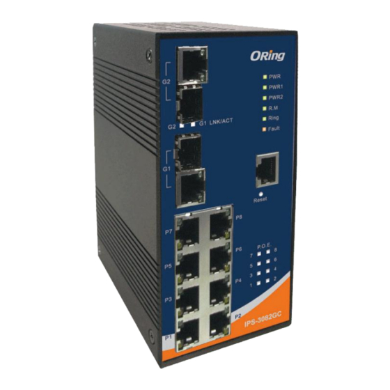
IPS-3082GC-AT User’s Manual ardware Overview 3.1 Front Panel The following table describes the labels that stick on the IPS-3082GC-AT. Port Description 10/100 RJ-45 fast 8 10/100Base-T(X) RJ-45 fast Ethernet ports support auto-negotiation. Ethernet ports Default Setting : Speed: auto Duplex: auto... - Page 12 IPS-3082GC-AT User’s Manual IPS-3082GC-AT 1. LED for PWR. When the PWR links, the green led will be light on. 2. LED for PWR1. When the PWR1 links, the green led will be light on. 3. LED for PWR2. When the PWR2 links, the green led will be light on.
-
Page 13: Front Panel Leds
IPS-3082GC-AT User’s Manual 3.2 Front Panel LEDs Color Status Description Green DC power ready Green DC power module 1 activated. Green DC power module 2 activated. Green O-Ring Master. O-Ring enabled. Ring Green Slowly blinking O-Ring topology has problem Fast blinking O-Ring work normally. -
Page 14: Top View Panel
IPS-3082GC-AT User’s Manual 3.3 Top view Panel The bottom panel components of IPS-3082GC-AT are shown as below: 1. Terminal block includes: 2. Ground wire ORing Industrial Networking Corp... -
Page 15: Cables
4.1 Ethernet Cables The IPS-3082GC-AT switch have standard Ethernet ports. According to the link type, the switches use CAT 3, 4, 5, 5e UTP cables to connect to any other network device (PCs, servers, switches, routers, or hubs). Please refer to the following table for cable specifications. - Page 16 BI_DC- BI_DB- BI_DD+ BI_DD- The IPS-3082GC-AT switch support auto MDI/MDI-X operation. You can use a straight-through cable to connect PC to switch. The following table below shows the 10BASE-T/ 100BASE-TX MDI and MDI-X port pin outs. 10/100 Base-TX MDI/MDI-X pins assignment...
-
Page 17: Sfp
Fiber cord 4.3 Console Cable IPS-3082GC-AT switches can be management by console port. The DB-9 to RJ-45 cable can be found in the package. You can connect them to PC via a RS-232 cable with DB-9 female connector and the other end (RJ-45 connector) connects to console port of switch. -
Page 18: Web Management
IPS-3082GC-AT User’s Manual EB Management 5.1 Configuration by Web Browser This section introduces the configuration by Web browser. 5.1.1 About Web-based Management An embedded HTML web site resides in flash memory on the CPU board. It contains advanced management features and allows you to manage the switch from anywhere on the network through a standard web browser such as Microsoft Internet Explorer. - Page 19 IPS-3082GC-AT User’s Manual The login screen appears. Key in the username and password. The default username and password is “admin”. Click “Enter” or ”OK” button, then the main interface of the Web-based management appears. Login screen Main Interface Main interface...
-
Page 20: System Information
, PWR1, PWR2 and PWR3 LEDs of the switch will start to flash together, and click , the LEDs will stop flashing. 5.1.3 Front Panel Show the panel of IPS-3082GC-AT. Click “Close” to close panel on web. ORing Industrial Networking Corp... -
Page 21: Basic Setting
IPS-3082GC-AT User’s Manual 5.1.4 Basic setting 5.1.4.1 Switch Setting Switch setting interface The following table describes the labels in this screen. Label Description System Name Assign the name of switch. The maximum length is 64 bytes System Description Display the description of switch. -
Page 22: Ip Setting
IPS-3082GC-AT User’s Manual The following table describes the labels in this screen. Label Description Key in the new username (The default is “admin”) User name Key in the new password (The default is “admin”) New Password Confirm password Re-type the new password. -
Page 23: Ipv6 Setting
IPS-3082GC-AT User’s Manual switch and it will be display in this column. The default IP is 192.168.10.1 Assign the subnet mask of the IP address. If DHCP client Subnet Mask function is enabling, you do not need to assign the subnet mask Gateway Assign the network gateway for the switch. -
Page 24: Time Setting
IPS-3082GC-AT User’s Manual (link) or the broadcast domain that the host is connected to. 5.1.4.5 Time Setting This page includes configurations of SNTP and system clock. System Clock The following table describes the labels in this screen. Label Description System clock This field shows the current system timer. - Page 25 IPS-3082GC-AT User’s Manual SNTP The SNTP (Simple Network Time Protocol) settings allow you to synchronize switch clocks in the Internet. SNTP Configuration interface The following table describes the labels in this screen. Label Description SNTP Client Enable or disable SNTP function to get the time from the SNTP server.
- Page 26 IPS-3082GC-AT User’s Manual CDT - Central Daylight CST - Central Standard -6 hours 6 am MDT - Mountain Daylight MST - Mountain Standard -7 hours 5 am PDT - Pacific Daylight PST - Pacific Standard -8 hours 4 am ADT - Alaskan Daylight...
- Page 27 IPS-3082GC-AT User’s Manual Guam Standard, USSR Zone 9 IDLE - International Date Line NZST - New Zealand +12 hours Midnight Standard NZT - New Zealand Label Description SNTP Sever IP Set the SNTP server IP address. Address Set up the Daylight Saving beginning time and Daylight Saving...
-
Page 28: Lldp
IPS-3082GC-AT User’s Manual 5.1.4.6 LLDP LLDP (Link Layer Discovery Protocol) function allows the switch to advertise its information to other nodes on the network and store the information it discovers. LLDP configuration interface The following table describes the labels in this screen. -
Page 29: Backup & Restore
IPS-3082GC-AT User’s Manual Auto Provision interface 5.1.4.8 Backup & Restore You can save current EEPROM value from the switch to TFTP server, then go to the TFTP restore configuration page to restore the EEPROM value. ORing Industrial Networking Corp... - Page 30 IPS-3082GC-AT User’s Manual Backup & Restore interface The following table describes the labels in this screen. Label Description Fill in the TFTP server IP TFTP Server IP Address Fill the file name. Restore File Name Click “restore” to restore the configurations.
-
Page 31: Upgrade Firmware
IPS-3082GC-AT User’s Manual 5.1.4.9 Upgrade Firmware Upgrade Firmware allows you to update the switch firmware. Before updating, make sure you have your TFTP server ready and the firmware image is on the TFTP server. interface Update Firmware 5.1.4.10 Upgrade HTTPS Certification Upgrade HTTPS Certification,allows user to update the switch HTTPS Certification file. -
Page 32: Redundancy
IPS-3082GC-AT User’s Manual 5.1.5 Redundancy (*NOTE) 5.1.5.1 MRP MRP (Media Redundancy Protocol) Ring (IEC 62439) of up to 50 devices typically transforms back to a line structure within 80 ms (adjustable to max. 200 ms/500 ms). Label Description Enable Enabling the MRP function... - Page 33 IPS-3082GC-AT User’s Manual O-Ring interface The following table describes the labels in this screen. Label Description Enable Ring Mark to enable Ring. There should be one and only one Ring Master in a ring. Enable Ring Master However if there are two or more switches which set Ring Master to enable, the switch with the lowest MAC address will be the actual Ring Master and others will be Backup Masters.
-
Page 34: Open-Ring
5.1.5.3 OPEN-Ring Open-Ring technology can be applied for other vendor’s proprietary ring. Thus, you can add switches of ORing into the network constructed by other ring technology and enable Open-Ring to co-operate with other vendor’s managed switch. Open-Ring interface... -
Page 35: O-Chain
IPS-3082GC-AT User’s Manual Open-Ring connection 5.1.5.4 O-Chain O-Chain is the revolutionary network redundancy technology that provides the add-on network redundancy topology for any backbone network, providing ease-of-use while maximizing fault-recovery swiftness, flexibility, compatibility, and cost-effectiveness in one set of network redundancy topologies O-Chain allows multiple redundant network rings of different redundancy protocols to join and function together as a larger and more robust compound network topology, i.e. -
Page 36: Rstp-Repeater
IPS-3082GC-AT User’s Manual Ring Port Choosing the port which connect to the ring Ring Port Choosing the port which connect to the ring Edge Port In the O-Chain application, the head and tail of two Switch Port, must start the Edge,MAC smaller Switch, Edge port will be the backup and RM LED Light. -
Page 37: Fast Recovery
IPS-3082GC-AT User’s Manual 5.1.5.6 Fast Recovery The Fast Recovery Mode can be set to connect multiple ports to one or more switches. The Switch with its fast recovery mode will provide redundant links. Fast Recovery mode supports 5 priorities, only the first priority will be the act port, the other ports configured with other priority will be the backup ports. - Page 38 IPS-3082GC-AT User’s Manual RSTP Setting interface The following table describes the labels in this screen. Label Description You must enable or disable RSTP function before configuring RSTP mode the related parameters. A value used to identify the root bridge. The bridge with the...
- Page 39 IPS-3082GC-AT User’s Manual Label Description The cost of the path to the other bridge from this transmitting Path Cost (1-200000000) bridge at the specified port. Enter a number 1 through 200000000. Decide which port should be blocked by priority in LAN.
-
Page 40: Mstp
IPS-3082GC-AT User’s Manual RSTP are dependent upon whether the port concerned can only be connected to exactly one other bridge (i.e. It is served by a point-to-point LAN segment), or it can be connected to two or more bridges (i.e. It is served by a shared medium LAN segment). - Page 41 IPS-3082GC-AT User’s Manual MSTP Setting interface The following table describes the labels in this screen. Label Description MSTP Enable You must enable or disable MSTP function before configuring the related parameters. Force Version The Force Version parameter can be used to force a VLAN Bridge that supports RSTP to operate in an STP-compatible manner.
- Page 42 IPS-3082GC-AT User’s Manual a reconfiguration. Enter a value between 6 through 40. Hello Time (1-10) The setting follow the rule below to configure the MAX Age, Hello Time, and Forward Delay Time at controlled switch sends out the BPDU packet to check RSTP current status. Enter a value between 1 through 10.
- Page 43 IPS-3082GC-AT User’s Manual Admin P2P Some of the rapid state transactions that are possible within RSTP are dependent upon whether the port concerned can only be connected to exactly one other bridge (i.e. It is served by a point-to-point LAN segment), or it can be connected to two or more bridges (i.e.
- Page 44 IPS-3082GC-AT User’s Manual MSTP Instance Port interface Label Description Set the instance’s information except CIST Instance Port Selecting the port that you want to configure. Priority (0-240) Decide which port should be blocked by priority in LAN. Enter a number 0 through 240. The value of priority must be the multiple...
-
Page 45: Multicast
IPS-3082GC-AT User’s Manual 5.1.6 Multicast 5.1.6.1 IGMP Snooping Internet Group Management Protocol (IGMP) is used by IP hosts to register their dynamic multicast group membership. IGMP has 3 versions, IGMP v1, v2 and v3. Please refer to RFC 1112, 2236 and 3376. IGMP Snooping improves the performance of networks that carry multicast traffic. -
Page 46: Mvr
IPS-3082GC-AT User’s Manual 5.1.6.2 MVR Function can provide a different VLAN users to receive MVR Mode VLAN Multicast Packet. Label Description Enable or Disable MVR Mode MVR Mode Setting MVR VLAN MVR VLAN Setting Port Type to inactive、Receiver、Source TYPE Enable or disable Immediate leave... -
Page 47: Static Multicast Filtering
IPS-3082GC-AT User’s Manual 5.1.6.3 Static Multicast Filtering Static Multicast filtering is the system by which end stations only receive multicast traffic if they register to join specific multicast groups. With multicast filtering, network devices only forward multicast traffic to the ports that are connected to registered end stations. -
Page 48: Port Setting
IPS-3082GC-AT User’s Manual 5.1.7 Port Setting 5.1.7.1 Port Control By this function, you can set the state, speed/duplex, flow control, and security of the port. Port Control interface The following table describes the labels in this screen. Label Description Port NO. -
Page 49: Port Status
IPS-3082GC-AT User’s Manual 5.1.7.2 Port Status The following information provides the current port status information Port Status interface 5.1.7.3 Port Alias The user can define the name of every Ports. Can let user, convenient management every Port. 5.1.7.4 Rate Limit By this function, you can limit traffic of all ports, including broadcast, multicast and flooded unicast. -
Page 50: Port Trunk
IPS-3082GC-AT User’s Manual Rate Limit interface The following table describes the labels in this screen. Label Description You can set “all”, “Broadcast only”, ”Broadcast/Multicast” Ingress Limit Frame or ”Broadcast/Multicast/Flooded Unicast” mode. Type Ingress The switch port received traffic. Egress The switch port transmitted traffic. - Page 51 IPS-3082GC-AT User’s Manual Port Trunk - Setting interface The following table describes the labels in this screen. Label Description Select port to join a trunk group. Group ID Support static trunk and 802.3ad LACP Type Select the number of active ports in dynamic group (LACP).
-
Page 52: Loop Guard
IPS-3082GC-AT User’s Manual other inactive ports in dynamic group will be suspended (no traffic). Once the active port is broken, the suspended port will be active automatically. Click “Apply” to set the configurations. Apply Port Trunk – Status Port Trunk - Status interface... -
Page 53: Vlan
IPS-3082GC-AT User’s Manual 5.1.8 VLAN A Virtual LAN (VLAN) is a logical network grouping that limits the broadcast domain, which allows you to isolate network traffic. Only the members of the VLAN will receive traffic from the same members of VLAN. Basically, creating a VLAN from a switch is logically equivalent of reconnecting a group of network devices to another Layer 2 switch. -
Page 54: Vlan Setting - Port Based
IPS-3082GC-AT User’s Manual The following table describes the labels in this screen. Label Description Configure VLAN Operation Mode: disable, Port Base,802.1Q VLAN Operation Mode Enable/Disable GVRP function. GVRP Mode Management VLAN can provide network administrator a Management VLAN ID secure VLAN to management Switch. Only the devices in the management VLAN can access the switch. - Page 55 IPS-3082GC-AT User’s Manual VLAN Configuration – Port Base interface-1 The following table describes the labels in this screen. Label Description Click “add” to enter VLAN add interface. Edit exist VLAN Edit Delete exist VLAN Delete Show help file. Help ORing Industrial Networking Corp...
- Page 56 IPS-3082GC-AT User’s Manual VLAN Configuration – Port Base interface-2 The following table describes the labels in this screen. Label Description VLAN name. Group Name Specify the VLAN ID VLAN ID Select port to join the VLAN group. Remove port of the VLAN group Remove Click “Apply”...
-
Page 57: Traffic Priorilization
IPS-3082GC-AT User’s Manual 5.1.9 Traffic Priorilization Traffic Prioritization includes 3 modes: port base, 802.1p/COS, and TOS/DSCP. By traffic prioritization function, you can classify the traffic into four classes for differential network application. IGS-3044GP(GC) series support 4 priority queues. 5.1.9.1 Qos policy Traffic Prioritization interface The following table describes the labels in this screen. -
Page 58: Port-Base Priority
IPS-3082GC-AT User’s Manual 5.1.9.2 Port-base priority Port-based Priority interface The following table describes the labels in this screen Assign Port with a priority queue. 4 priority queues can be Port base Priority assigned: High, Middle, Low, and Lowest. Click “Apply” to set the configurations. -
Page 59: Tos/Dscp
IPS-3082GC-AT User’s Manual The following table describes the labels in this screen COS (Class Of Service) is well known as 802.1p. It describes COS/802.1p that the output priority of a packet is determined by user priority field in 802.1Q VLAN tag. The priority value is supported 0to7.COS value map to 4 priority queues: High,... -
Page 60: Dhcp Server / Relay
IPS-3082GC-AT User’s Manual 5.1.10 DHCP Server / Relay 5.1.10.1 DHCP Server – Setting The system provides with DHCP server function. Enable the DHCP server function, the switch system will be a DHCP server. DHCP Server Configuration interface The following table describes the labels in this screen. -
Page 61: Dhcp Server - Client List
IPS-3082GC-AT User’s Manual 5.1.10.2 DHCP Server – Client List When the DHCP server function is activated, the system will collect the DHCP client information and display in here. DHCP Server Client Entries interface 5.1.10.3 DHCP Server – Port and IP bindings You can assign the specific IP address which is in the assigned dynamic IP range to the specific port. - Page 62 IPS-3082GC-AT User’s Manual The following table describes the labels in this screen. Label Description Enable/Disable DHCP Relay Agent. DHCP Relay Specify the IP address and VID of DHCP server. Keep "0.0.0.0" means DHCP Server IP server is inactive. Address and VID...
-
Page 63: Snmp
IPS-3082GC-AT User’s Manual "Option 82 Remote ID" provides a identifier for the remote server. DHCP Option 82 There are 4 types supported: IP, MAC, Client-ID, and Other. Remote ID "Option 82 Circuit-ID" encodes an agent-local identifier of the circuit DHCP Option 82 from which a DHCP client-to-server packet was received. -
Page 64: Snmp -Trap Setting
IPS-3082GC-AT User’s Manual V2c, and SNMP V3. SNMP V1/SNMP V2c agent use a community string match for authentication, that means SNMP servers access objects with read-only or read/write permissions with the community default string public/private. SNMP V3 requires an authentication level of MD5 or DES to encrypt data to enhance data security. -
Page 65: Snmpv3
IPS-3082GC-AT User’s Manual The following table describes the labels in this screen. Label Description Server IP The server IP address to receive Trap Community Community for authentication Trap Version supports V1 and V2c and V3 Trap Version Add trap server profile. - Page 66 IPS-3082GC-AT User’s Manual The following table describes the labels in this screen Label Description Configure SNMP v3 context table. Assign the context name of Context Table context table. Click "Apply" to change context name 1. Configure SNMP v3 user table.
-
Page 67: Security
IPS-3082GC-AT User’s Manual 1. Configure SNMP v3 access table. Access Table 2. Context Prefix: set up the context name. 3. Group Name: set up the group. 4. Security Level: select the access level. 5. Context Match Rule: select the context match rule. -
Page 68: Static Mac Forwarding
IPS-3082GC-AT User’s Manual IP Security interface The following table describes the labels in this screen. Label Description Enable/Disable the IP security function. IP security MODE Enable WEB(HTTP) Mark the blank to enable WEB(HTTP) Management. Management Enable HTTPS Mark the blank to enable WEB(HTTPS) Management. -
Page 69: Mac Blacklist
IPS-3082GC-AT User’s Manual Port Security interface The following table describes the labels in this screen. Label Description Input MAC Address to a specific port. MAC Address Select port of switch. Port NO. Add an entry of MAC and port information. - Page 70 IPS-3082GC-AT User’s Manual The following table describes the labels in this screen. Label Description Input MAC Address to add to MAC Blacklist. MAC Address Select port of switch. Port NO. Add an entry to Blacklist table. Delete the entry. Delete Show help file.
- Page 71 IPS-3082GC-AT User’s Manual Enable or Disable 802.1X Radius Server function . 802.1x Portocol The IP address of the authentication server. Radius Server IP Set the UDP port number used by the authentication server to Server port authenticate. Set the UDP destination port for accounting requests to the specified Account port Radius Server.
-
Page 72: Ip Guard
IPS-3082GC-AT User’s Manual Label Description Port Authorized Mode Reject: force this port to be unauthorized. Accept: force this port to be authorized. Authorize: the state of this port was determined by the outcome of the 802.1x authentication. - Page 73 IPS-3082GC-AT User’s Manual IP Guard – Port Setting State interface The following table describes the labels in this screen. Label Description Mode Disable mode: function is totally disabled. Monitor mode: function is disabled, but keeps monitor the IP traffic.
- Page 74 IPS-3082GC-AT User’s Manual The following table describes the labels in this screen. Label Description IP address of the allowed entry. MAC address of the allowed entry. Port number of the allowed entry. Port If you doubt some allowed IP traffic are abnormal, you could Status block the traffic use this field.
-
Page 75: Tacacs
IPS-3082GC-AT User’s Manual IP Guard – Super-IP List State interface IP Guard – Super-IP List IP Guard is an intelligent and easy use function for IP security. It could protect the network from unknown IP( the IP not in allowed list) attack. The illegal IP traffic will be blocked. -
Page 76: Warning
IPS-3082GC-AT User’s Manual The following table describes the labels in this screen. Label Description Enable check box Enable / disable server connect Input TACACS+ Server IP Address . Server IP Address Input TACACS+ use Port number Port Input TACACS+ use key value( need same TACACS+ Server) - Page 77 IPS-3082GC-AT User’s Manual Warning – Fault Relay Alarm When any selected fault event is happened, the Fault LED in switch panel will light up and the electric relay will signal at the same time. System Warning – SYSLOG Setting The SYSLOG is a protocol to transmit event notification messages across networks.
- Page 78 IPS-3082GC-AT User’s Manual Both: log to both of local and remote server. The remote SYSLOG Server IP address. SYSLOG Server IP Address Click “Apply” to set the configurations. Apply Show help file. Help System Warning – SMTP Setting The SMTP is Short for Simple Mail Transfer Protocol. It is a protocol for e-mail transmission across the Internet.
- Page 79 IPS-3082GC-AT User’s Manual The recipient's E-mail address. It supports 6 recipients for a Recipient E-mail Address mail. Click “Apply” to set the configurations. Apply Show help file. Help System Warning – Event Selection SYSLOG and SMTP are the two warning methods that supported by the system. Check the corresponding box to enable system event warning method you wish to choose.
-
Page 80: Monitor And Diag
IPS-3082GC-AT User’s Manual Link Up Link Down Link Up & Link Down Click “Apply” to set the configurations. Apply Show help file. Help 5.1.14 Monitor and Diag 5.1.14.1 System Event Log If system log client is enabled, the system event logs will be shown in this table. -
Page 81: Mac Address Table
IPS-3082GC-AT User’s Manual Clear Clear log. Help Show help file. 5.1.14.2 MAC Address Table Refer to IEEE 802.1 D Sections 7.9. The MAC Address Table, that is Filtering Database, supports queries by the Forwarding Process, as to whether a frame received by a given port with a given destination MAC address is to be forwarded through a given potential transmission port. -
Page 82: Port Overview
IPS-3082GC-AT User’s Manual Down MAC Address Auto Enable or Disable MAC Learning function . Learning Click “Apply” to set the configurations. Apply 5.1.14.3 Port Overview Port statistics show several statistics counters for all ports Port Overview interface The following table describes the labels in this screen. -
Page 83: Port Counters
IPS-3082GC-AT User’s Manual 5.1.14.4 Port Counters This page shows statistic counters for the port. The "Clear" button is to reset all counters to zero for all ports. Port Counters interface The following table describes the labels in this screen. Label Description The lower 32-bits of the 64-bit InGoodOctets counter. - Page 84 IPS-3082GC-AT User’s Manual half-duplex only. The number of good frames received that have a Broadcast InBroadcasts destination MAC address. The number of good frames received that have a Multicast InMulticasts destnation MAC address. Total frames received (and/or transmitted) with a length of exactly Octets64 64 octes, include those with errors.
-
Page 85: Port Monitoring
IPS-3082GC-AT User’s Manual half-duplex only. Total frames received with a length of less than 64 octets but with Undersize a valid FCS. Total frames received with a length of more than 64 octets and Fragments with a invalid FCS. Total frames received with a length of more than MaxSize octets Oversize but with a valid FCS. -
Page 86: Traffic Monitor
IPS-3082GC-AT User’s Manual The following table describes the labels in this screen. Label Description Destination Port The port will receive a copied frame from source port for monitoring purpose. The port will be monitored. Mark the blank of TX or RX to be Source Port monitored. -
Page 87: Sfp Monitor
IPS-3082GC-AT User’s Manual 5.1.14.7 SFP Monitor DDM function, can pass SFP module which supports DDM function, measure the temperature of the apparatus .And manage and set up event alarm module through DDM WEB Label Description Warning Temperature Setting Warning Temperature... -
Page 88: Power Over Ethernet (P.o.e.)
IPS-3082GC-AT User’s Manual The following table describes the labels in this screen. Label Description IP Address Enter the IP address that you want to detect. Click “Active” to send ICMP packets Active 5.1.15 Power over Ethernet (P.O.E.) 5.1.15.1 System setting The following interface is the P.O.E. -
Page 89: Power Over Ethernet - Port Control
IPS-3082GC-AT User’s Manual Switch POE Chip Temperature (°C) PoE Chip Temperature POE Chip Status POE Chip work status . 5.1.15.2 Power over Ethernet - Port Control The following interface is the P.O.E. setting interface. There are 8 ports (port 1 to port 8) act as P.S.E. -
Page 90: Port Status
IPS-3082GC-AT User’s Manual 5.1.15.3 Port Status Show P.O.E. each Port, the situation in detail. Label Description Port Port number. Link P.S.E. Function Port Link or Down State Show P.S.E. Status. Set the “Power Limit From Classification” function for each Power Limit From P.O.E. -
Page 91: Ping Alive Check
IPS-3082GC-AT User’s Manual Label Description Port Port number. Delay Mode Enable or disable Delay Mode Delay Time(0-300) Time to provide power 5.1.15.5 Ping Alive Check You can control the P.O.E. function by using the ping command , in order to turn on or off other P.O.E. -
Page 92: Schedule
IPS-3082GC-AT User’s Manual Failure Action Set up movements wanted to carry out Reboot Time Switch ping check failure " P.O.E. " restarts the buffer time of switch. Event Alarm by SMTP Sent alarm message form SMTP mail . 5.1.15.6 Schedule... -
Page 93: Save Configuration
IPS-3082GC-AT User’s Manual 5.1.16 Save Configuration If any configuration changed, “Save Configuration” should be clicked to save current configuration data to the permanent flash memory. Otherwise, the current configuration will be lost when power off or system reset. System Configuration interface The following table describes the labels in this screen. -
Page 94: Command Line Interface Management
IPS-3082GC-AT User’s Manual ommand Line Interface Management About CLI Management Besides WEB-base management, IPS-3082GC-AT also supports CLI management. You can use console or telnet to management switch by CLI. CLI Management by RS-232 Serial Console (9600, 8, none, 1, none) Before Configuring by RS-232 serial console, use an RJ45 to DB9-F cable to connect the Switches’... - Page 95 IPS-3082GC-AT User’s Manual Step 2. Input a name for new connection Step 3. Select to use COM port number ORing Industrial Networking Corp...
- Page 96 IPS-3082GC-AT User’s Manual Step 4. The COM port properties setting, 9600 for Bits per second, 8 for Data bits, None for Parity, 1 for Stop bits and none for Flow control. Step 5. The Console login screen will appear. Use the keyboard to enter the Username and Password (The same with the password for Web Browser), then press “Enter”.
- Page 97 IPS-3082GC-AT User’s Manual The default value is as below: IP Address: 192.168.10.1 Subnet Mask: 255.255.255.0 Default Gateway: 192.168.10.254 User Name: admin Password: admin Follow the steps below to access the console via Telnet. Step 1. Telnet to the IP address of the switch from the Windows “Run“ command (or from the MS-DOS prompt) as below.
- Page 98 IPS-3082GC-AT User’s Manual Commands Level Modes Access Method Prompt Exit Method About This Model User EXEC Begin a session switch> Enter logout The user command with your switch. available at the level of or quit. user is the subset of those available at the privileged level.
-
Page 99: Commands Set List-System Commands Set
IPS-3082GC-AT User’s Manual Symbol of Command Level. Mode Symbol of Command Level User EXEC Privileged EXEC Global configuration VLAN database Interface configuration Commands Set List—System Commands Set IPS-3082GC-AT Level Description Example Commands show config Show switch switch>show config configuration show terminal... - Page 100 IPS-3082GC-AT User’s Manual show ip Show IP information of switch#show ip switch no ip dhcp Disable DHCP client switch(config)#no ip dhcp function of switch reload Halt and perform a switch(config)#reload cold restart default Restore to default Switch(config)#default admin username Changes a login...
-
Page 101: Commands Set List-Port Commands Set
IPS-3082GC-AT User’s Manual server no dhcpserver Disable DHCP server switch(config)#no dhcpserver function security enable Enable IP security switch(config)#security enable function Enable IP security of switch(config)#security http security http HTTP server security telnet Enable IP security of switch(config)#security telnet telnet server... - Page 102 IPS-3082GC-AT User’s Manual operation for Fast Ethernet., the speed can’t be set to 1000 if the port isn’t a giga port.. flowcontrol mode Use the flowcontrol switch(config)#interface [Symmetric|Asymmetric] configuration fastEthernet 2 command on Ethernet switch(config-if)#flowcontrol mode ports to control traffic...
- Page 103 IPS-3082GC-AT User’s Manual Range is from 100 switch(config-if)#bandwidth in 100 kbps to 102400 kbps or to 256000 kbps for giga ports, and zero means no limit. bandwidth out Set interface output switch(config)#interface [Value] bandwidth. Rate fastEthernet 2 Range is from 100...
-
Page 104: Commands Set List-Trunk Command Set
IPS-3082GC-AT User’s Manual switch(config-if)#show interface accounting no accounting Clear interface switch(config)#interface accounting fastEthernet 2 information switch(config-if)#no accounting Commands Set List—Trunk command set IPS-3082GC-AT Level Description Example Commands aggregator priority Set port group system switch(config)#aggregator priority 22 [1to65535] priority aggregator activityport... -
Page 105: Commands Set List-Vlan Command Set
IPS-3082GC-AT User’s Manual comma(ex.2, 3, 6) show aggregator Show the information switch#show aggregator of trunk group no aggregator lacp Disable the LACP switch(config)#no aggreator lacp 1 [GroupID] function of trunk group Remove a trunk group switch(config)#no aggreator group 2 no aggregator group [GroupID] Commands Set List—VLAN command set... -
Page 106: Commands Set List-Spanning Tree Command Set
IPS-3082GC-AT User’s Manual vlan 8021q aggreator Assign a access link switch(vlan)#vlan 8021q aggreator 3 [TrunkID] for VLAN by trunk access-link untag 33 access-link untag group [UntaggedVID] Assign a trunk link for switch(vlan)#vlan 8021q aggreator 3 vlan 8021q aggreator [TrunkID] VLAN by trunk group... - Page 107 IPS-3082GC-AT User’s Manual does not receive a bridge protocol data unit (BPDU) message from the root switch within this interval, it recomputed the Spanning Tree Protocol (STP) topology. spanning-tree Use the spanning-tree switch(config)#spanning-tree hello-time [seconds] hello-time global hello-time 3 configuration...
- Page 108 IPS-3082GC-AT User’s Manual Protocol (STP) calculations. In the event of a loop, spanning tree considers the path cost when selecting an interface to place into the forwarding state. stp-path-priority Use the spanning-tree switch(config)#interface fastEthernet [Port Priority] port-priority interface configuration switch(config-if)# stp-path-priority...
-
Page 109: Commands Set List-Qos Command Set
IPS-3082GC-AT User’s Manual Commands Set List—QoS command set IPS-3082GC-AT Level Description Example Commands qos policy Select QOS policy switch(config)#qos policy scheduling weighted-fair [weighted-fair|strict] Setting of QOS switch(config)#qos prioritytype qos prioritytype [port-based|cos-only|tos priority type -only|cos-first|tos-first] qos priority portbased Configure Port-based switch(config)#qos priority portbased... -
Page 110: Commands Set List-Mac/Filter Table Command Set
IPS-3082GC-AT User’s Manual entries. no igmp Disable IGMP switch(config)#no igmp snooping function no igmp-query Disable IGMP query switch#no igmp-query Commands Set List—MAC/Filter Table command set IPS-3082GC-AT Level Description Example Commands mac-address-table static Configure MAC switch(config)#interface fastEthernet hwaddr address table of [MAC] interface (static). - Page 111 IPS-3082GC-AT User’s Manual Commands snmp agent-mode Select the agent mode switch(config)#snmp agent-mode [v1v2c | v3] of SNMP v1v2c snmp-server host Configure SNMP switch(config)#snmp-server host [IP address] server host 192.168.10.50 community public information and trap-version v1 community [Community-string] community string (remove)
-
Page 112: Commands Set List-Port Mirroring Command Set
IPS-3082GC-AT User’s Manual 6.11 Commands Set List—Port Mirroring command set IPS-3082GC-AT Level Description Example Commands Set RX destination switch(config)#monitor rx monitor rx port of monitor function monitor tx Set TX destination switch(config)#monitor tx port of monitor function Show port monitor... - Page 113 IPS-3082GC-AT User’s Manual global configuration command to change the radious server port 8021x system Use the 802.1x switch(config)# 8021x system system account port accountport 1816 accountport [port ID] global configuration command to change the accounting port 8021x system sharekey Use the 802.1x...
-
Page 114: Commands Set List-Tftp Command Set
IPS-3082GC-AT User’s Manual command to set the server timeout. 8021x misc maxrequest Use the 802.1x misc switch(config)# 8021x misc max request global maxrequest 3 [number] configuration command to set the MAX requests. Use the 802.1x misc switch(config)# 8021x misc 8021x misc reauthperiod [sec.]... -
Page 115: Commands Set List-Syslog, Smtp, Event Command Set
IPS-3082GC-AT User’s Manual name of image. restore flash:restore_cfg Get configuration from switch(config)#restore TFTP server and need flash:restore_cfg to specify the IP of TFTP server and the file name of image. Upgrade firmware by switch(config)#upgrade upgrade flash:upgrade_fw TFTP and need to... - Page 116 IPS-3082GC-AT User’s Manual [password] authentication password smtp rcptemail Configure Rcpt e-mail switch(config)#smtp rcptemail 1 [Index] [Email address] Address Alert@test.com show smtp Show the information switch#show smtp of SMTP no smtp Disable SMTP switch(config)#no smtp function event device-cold-start Set cold start event...
-
Page 117: Commands Set List-Sntp Command Set
IPS-3082GC-AT User’s Manual show systemlog Show system log switch#show systemlog client & server information 6.15 Commands Set List—SNTP command set IPS-3082GC-AT Level Description Example Commands sntp enable Enable SNTP function switch(config)#sntp enable sntp daylight Enable daylight saving switch(config)#sntp daylight time, if SNTP function is inactive, this command can’t be... -
Page 118: Commands Set List-O-Ring Command Set
IPS-3082GC-AT User’s Manual number show sntp Show SNTP switch#show sntp information show sntp timezone Show index number of switch#show sntp timezone time zone list Disable SNTP switch(config)#no sntp no sntp function no sntp daylight Disable daylight switch(config)#no sntp daylight saving time 6.16 Commands Set List—O-Ring command set... - Page 119 Technical Specifications ORing Switch Model IPS-3082GC-AT Physical Ports 10/100 Base-T(X) Ports in RJ45 Auto MDI/MDIX with P.S.E. Gigabit Combo Ports with 10/100/1000Base-T(X) and 100/1000Base-X SFP port Technology IEEE 802.3 for 10Base-T IEEE 802.3u for 100Base-TX and 100Base-FX IEEE 802.3z for 1000Base-X IEEE 802.3ab for 1000Base-T...
- Page 120 IPS-3082GC-AT User’s Manual Syslog server / client to record and view events Include SMTP for event warning notification via email Event selection support DDM Function Voltage / Current / Temperature RS-232 Serial Console Port RS-232 in RJ45 connector with console cable. 9600bps, 8, N, 1...
Need help?
Do you have a question about the IPS-3082GC-AT and is the answer not in the manual?
Questions and answers