Table of Contents
Advertisement
Quick Links
Industrial
Lite-managed Ethernet Switch
IES-2050 User's Manual
Version 1.0
May, 2008.
ORing Industrial Networking Corp.
4F., NO.3, Lane235, Baociao Rd.Sindian City,
Taipei County 23145 Taiwan, R.O.C.
Tel: + 886 2 2918 3036
Fax: + 886 2 2918 3084
Website: www.oring-networking.com
E-mail:
support@oring-networking.com
Advertisement
Table of Contents

Related Manuals for ORiNG IES-2050


Summary of Contents for ORiNG IES-2050
- Page 1 Industrial Lite-managed Ethernet Switch IES-2050 User’s Manual Version 1.0 May, 2008. ORing Industrial Networking Corp. 4F., NO.3, Lane235, Baociao Rd.Sindian City, Taipei County 23145 Taiwan, R.O.C. Tel: + 886 2 2918 3036 Fax: + 886 2 2918 3084 Website: www.oring-networking.com E-mail: support@oring-networking.com...
-
Page 2: Table Of Contents
Table of Content Getting to Know Your Switch................3 About the IES-2050 Lite-Managed Industrial Switch ..........3 Software Features ....................3 Hardware Features....................3 Hardware Installation..................4 Installing IES-2050 on DIN-Rail ................4 Installing IES-2050 on the wall ................. 5 Hardware Overview..................6 Front Panel....................... - Page 3 SNMP –Trap Setting ................. 26 5.1.6 VLAN........................27 5.1.6.1 VLAN Configuration – Port Based............. 27 5.1.7 Warning......................28 5.1.7.1 Fault Alarm ....................28 5.1.8 Front Panel ......................31 5.1.9 Save Configuration .................... 32 5.1.10 LLDP......................32 Technical Specifications ................34 ORing Industrial Networking Corp.
-
Page 4: Getting To Know Your Switch
The IES-2050 switch is cost-effect and powerful industrial switch with many features. These switches can work under wide temperature and dusty environment and humid condition. The IES-2050 switch can be managed by WEB and a useful Window Utility we called Open-Vision. -
Page 5: Hardware Installation
Installation Installing IES-2050 on DIN-Rail Each IES-2050 switch has a DIN-Rail kit on rear panel. The DIN-Rail kit helps switch to fix on the DIN-Rail. It is easy to install the switch on the DIN-Rail: Step 1: Slant the switch and mount the metal spring to DIN-Rail. -
Page 6: Installing Ies-2050 On The Wall
IES-2050 User’s Manual Installing IES-2050 on the wall Each IES-2050 switch has another installation method for users to fix the switch on the wall by the wall mount planet. The following steps show how to mount the switch on the wall: Step 1: Remove DIN-Rail kit. -
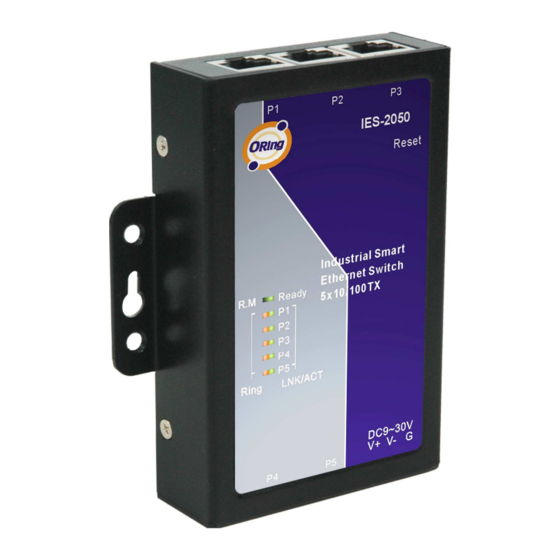
Page 7: Hardware Overview
IES-2050 User’s Manual ardware Overview Front Panel The following table describes the labels that stick on the IES-2050. Port Description 10/100 RJ-45 fast 10/100Base-T(X) RJ-45 fast Ethernet ports support Ethernet ports auto-negotiation. Default Setting : Speed: auto Duplex: auto Flow control : disable Push reset button 2 to 3 seconds to reset the switch. -
Page 8: Front Panel Leds
Port link up. LNK / ACT Green Blinking Data transmitted. Bottom Panel The bottom panel components of IES-2050 are showed as below: 1. Terminal block includes: 9 ~ 30V DC 2. RJ45 Ethernet port RJ45 Jack RJ45 Jack DC 9~30V power input IES-2050 bottom panel ORing Industrial Networking Corp. -
Page 9: Rear Panel
IES-2050 User’s Manual Rear Panel The rear panel components of IES-2050 are showed as below: 1. Screw holes for wall mount kit. 2. Din-Rail kit ORing Industrial Networking Corp. -
Page 10: Cables
Ethernet Cables The IES-2050 switches have standard Ethernet ports. According to the link type, the switches use CAT 3, 4, 5,5e UTP cables to connect to any other network device (PCs, servers, switches, routers, or hubs). Please refer to the following table for cable specifications. - Page 11 IES-2050 User’s Manual MDI/MDI-X pins assignment Pin Number MDI port MDI-X port TD+(transmit) RD+(receive) TD-(transmit) RD-(receive) RD+(receive) TD+(transmit) Not used Not used Not used Not used RD-(receive) TD-(transmit) Not used Not used Not used Not used Note: “+” and “-” signs represent the polarity of the wires that make up each wire pair.
-
Page 12: Web Management
IES-2050 User’s Manual EB Management Configuration by Web Browser This section introduces the configuration by Web browser. 5.1.1 About Web-based Management An embedded HTML web site resides in flash memory on the CPU board. It contains advanced management features and allows you to manage the switch from anywhere on the network through a standard web browser such as Microsoft Internet Explorer. - Page 13 IES-2050 User’s Manual Login screen Main Interface Main interface ORing Industrial Networking Corp.
-
Page 14: Basic Setting
IES-2050 User’s Manual 5.1.2 Basic Setting 5.1.2.1 Switch setting Switch setting interface The following table describes the labels in this screen. Label Description System Name Assign the name of switch. The maximum length is 64 bytes System Description Display the description of switch. -
Page 15: Ip Configuration
IES-2050 User’s Manual Admin Password interface The following table describes the labels in this screen. Label Description User name Key in the new username (The default is “admin”) New Password Key in the new password (The default is “admin”) Confirm password Re-type the new password. -
Page 16: Sntp Configuration
IES-2050 User’s Manual client function is enabling, the switch will assign the IP address from the network DHCP server. The default IP address will be replaced by the IP address which the DHCP server has assigned. After clicking “Apply” button, a popup dialog will show up to inform you when the DHCP client is enabling. - Page 17 IES-2050 User’s Manual The following table describes the labels in this screen. Label Description Enable or disable SNTP function to get the time from the SNTP SNTP Client server. Daylight Saving Time Enable or disable daylight saving time function. When daylight saving time is enabling, you need to configure the daylight saving time period.
- Page 18 IES-2050 User’s Manual CET - Central European FWT - French Winter MET - Middle European +1 hour 1 pm MEWT - Middle European Winter SWT - Swedish Winter EET - Eastern European, USSR +2 hours 2 pm Zone 1 BT - Baghdad, USSR Zone 2...
-
Page 19: Backup & Restore
IES-2050 User’s Manual 5.1.2.5 Backup & Restore You can save current EEPROM value of the switch to TFTP server, then go to the TFTP restore configuration page to restore the EEPROM value. Backup & Restore interface The following table describes the labels in this screen. -
Page 20: Factory Default
IES-2050 User’s Manual Update Firmware interface 5.1.2.7 Factory Default Factory Default interface Reset switch to default configuration. Click Reset to reset all configurations to the default value. You can select “Keep current IP address setting” and “Keep current username & password” to prevent IP and username & password from default. -
Page 21: Port Status
IES-2050 User’s Manual port. Port Control interface The following table describes the labels in this screen. Label Description Port NO. Port number for setting. Enable/Disable the port. State Speed/Duplex You can set Auto-negotiation, 100 full,100 half,10 full,10 half mode. Flow Control Support symmetric and asymmetric mode to avoid packet loss when congestion occurred. -
Page 22: Redundancy
The Fast Recovery Mode can be set to connect multiple ports to one or more switches. The IES-2050 with its fast recovery mode will provide redundant links. Fast Recovery mode supports 4 priorities, only the first priority will be the act port, the other ports configured with other priority will be the backup ports. - Page 23 IES-2050 User’s Manual O-Ring interface The following table describes the labels in this screen. Label Description Mark to enable O-Ring. O-Ring Ring Master There should be one and only one Ring Master in a ring. However if there are two or more switches which set Ring Master to enable, the switch with the lowest MAC address will be the actual Ring Master and others will be Backup Masters.
-
Page 24: Rstp
IES-2050 User’s Manual Dual Homing Mark to enable Dual Homing. By selecting Dual Homing mode, O-Ring will be connected to normal switches through two RSTP links (ex: backbone Switch). The two links work as active/backup mode, and connect each O-Ring to the normal switches in RSTP mode. - Page 25 IES-2050 User’s Manual RSTP Setting interface The following table describes the labels in this screen. Label Description RSTP mode You must enable or disable RSTP function before configuring the related parameters. Priority (0-61440) A value used to identify the root bridge. The bridge with the lowest value has the highest priority and is selected as the root.
-
Page 26: Snmp Configuration
IES-2050 User’s Manual including STP mathematic calculation. False is including the STP mathematic calculation. Apply Click “Apply” to activate the configurations. NOTE: Follow the rule to configure the MAX Age, Hello Time, and Forward Delay Time: 2 x (Forward Delay Time value –1) ≥ Max Age value ≥ 2 x (Hello Time value +1) RSTP Information Show RSTP algorithm result at this table. -
Page 27: Snmp -Trap Setting
IES-2050 User’s Manual SNMP – Agent setting interface The following table describes the labels in this screen. Label Description SNMP – Agent SNMP Community should be set for SNMP. Four sets of "Community String/Privilege" are supported. Each Community Setting String is maximum 32 characters. Keep empty to remove this Community string. -
Page 28: Vlan
IES-2050 User’s Manual SNMP –Trap Setting interface The following table describes the labels in this screen. Label Description Server IP The server IP address to receive Trap Community Community for authentication Trap Version Trap Version supports V1 and V2c. Add trap server profile. -
Page 29: Warning
IES-2050 User’s Manual Group Mark the blank to assign the port into VLAN group. Apply Click “Apply” to activate the configurations. Help Show help file. 5.1.7 Warning Warning function is very important for managing switch. You can manage switch by SYSLOG, E-MAIL, and Fault Relay. - Page 30 IES-2050 User’s Manual System event log interface The following table describes the labels in this screen. Label Description Select LOG page. Page Reload To get the newest event logs and refresh this page. Clear Clear log. Help Show help file.
- Page 31 IES-2050 User’s Manual System Warning – SMTP Setting interface The following table describes the labels in this screen. Label Description E-mail Alarm Enable/Disable transmission system warning events by e-mail. Sender E-mail The SMTP server IP address Address Mail Subject The Subject of the mail Authentication Username: the authentication username.
-
Page 32: Front Panel
Port Event Disable Link Up Link Down Link Up & Link Down Apply Click “Apply” to activate the configurations. Show help file. Help 5.1.8 Front Panel Show IES-2050 panel. Click “Close” to close panel on web. ORing Industrial Networking Corp. -
Page 33: Save Configuration
IES-2050 User’s Manual Front panel interface 5.1.9 Save Configuration If any configuration changed, “Save Configuration” should be clicked to save current configuration data into the permanent flash memory. Otherwise, the current configuration will be lost when power off or system reset. - Page 34 IES-2050 User’s Manual LLDP interface The following table describes the labels in this screen. Label Description LLDP Protocol “Enable” or “Disable” LLDP function. LLDP Interval The interval of resend LLDP (by default at 30 seconds) Apply Click “Apply” to activate the configurations.
-
Page 35: Technical Specifications
IES-2050 User’s Manual echnical Specifications Technology Ethernet Standards IEEE802.3 10BASE-T IEEE802.3u 100BASE-TX IEEE802.3x Flow Control and Back pressure IEEE802.1D Spanning tree protocol IEEE802.1w Rapid Spanning tree protocol IEEE802.1AB LLDP MAC addresses 2048 Flow Control IEEE 802.3x Flow Control and Back-pressure... - Page 36 IES-2050 User’s Manual Dimensions(W x D x H) 88mm(W) x 102mm(D) x 24mm(H) Casing IP-30 protection Regulatory Approvals Regulatory Approvals FCC Part 15, CISPER (EN55022) class A EN61000-4-2 (ESD), EN61000-4-3 (RS), EN61000-4-4 (EFT), EN61000-4-5 (Surge), EN61000-4-6 (CS) Shock IEC 60068-2-27...
Need help?
Do you have a question about the IES-2050 and is the answer not in the manual?
Questions and answers