Table of Contents
Advertisement
Quick Links
PoE
SWITCH
Q
I
I N D U S T R I A L
uick
nstallation
Introduction
IPS-1042FA series
are unmanaged PoE Ethernet switches with 4 x 10/100Base-T(X)
P.S.E. and 2x100Base-FX ports.
IPS-1042FA series
system to transmit electrical power, along with data, to remote devices over standard
twisted-pair cable in an Ethernet network.
IPS-1042FA series
P.S.E. (Power Sourcing Equipment) ports. P.S.E. is a device (switch or hub for instance)
that will provide power in a PoE setup.
IPS-1042FA series
inputs, configurable relay output alarm and rigid IP-30 housing. In addition, the wide
o
operating temperature range from -40 to 75 C can satisfy most of operating environment.
Features
Provide 4x10/100Base-T(X) PoE(P.S.E.) and 2x100Base-FX single/multi-mode
fiber ports
Supports IEEE 802.3at compliant 30Watts PoE per port
Support auto-negotiation and auto-MDI/MDI-X
Support store and forward transmission
Support flow control
Support surge protection technology
Warning system by relay output
Slim type rigid IP-30 housing design
DIN-Rail and wall mounting enabled
Package Contents
The device is shipped with the following items. If any of these items is
missing or damaged, please contact your customer service representative for
assistance.
Contents
Pictures
IPS-1042FA-MM-SC or
IPS-1042FA-SS-SC
DIN-rail Kit
Wall-mount Kit
QIG
6-pin terminal block
Preparation
Before you begin installing the switch, make sure you have all of the package
contents available and a PC with Microsoft Internet Explorer 6.0 or later, for
using web-based system management tools.
Safety & Warnings
Elevated Operating Ambient: If installed in a closed or multi-unit rack
assembly, the operating ambient temperature of the rack environment may be
greater than room ambient. Therefore, consideration should be given to
installing the equipment in an environment compatible with the maximum
ambient temperature (Tma) specified by the manufacturer.
Q I G
IGPS-1042GPA
IPS-1042FA Series
G
uide
supports Power over Ethernet, a
has 4X10/100Base-T(X)
support redundant power
Dimension
IPS-1042FA
P1
P2 Fault
TX
6
RX
LINK/
ACT
TX
5
RX
4
3
2
Number
1
PoE
10/100TX
26.1
X 1
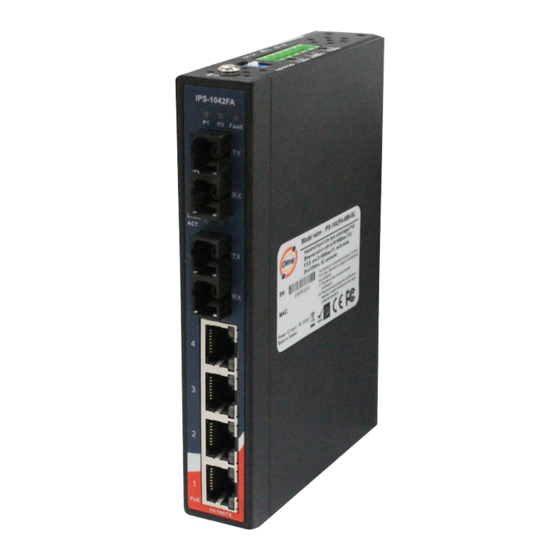
Panel Layouts
X 1
Front View
IPS-1042FA
1
X 2
P1
P2 Fault
TX
6
RX
7
LINK/
ACT
X 1
6
TX
5
RX
4
X 1
5
3
2
1
PoE
10/100TX
Top Panel
1
PWR-2
1A@24V
V2- V2+
1
2
1907-200-XX
Reduced Air Flow: Installation of the equipment in a rack should be such that the
amount of air flow required for safe operation of the equipment is not compromised.
Mechanical Loading: Mounting of the equipment in the rack should be such that a
hazardous condition is not achieved due to uneven mechanical loading.
Circuit Overloading: Consideration should be given to the connection of the equipment to
the supply circuit and the effect that overloading of the circuits might have on overcurrent
protection and supply wiring. Appropriate consideration of equipment nameplate ratings
should be used when addressing this concern.
Unit =mm (Tolerance ±0.5mm)
94.9
24.3
13.1
25.6
Ø3.0
Ø5.9
8.5
25.0
14.0
6.05
Rear View
1. Din-rail screw holes
1. PWR indicators
2
2. Faulty relay indicator
3. Link/Act LED for LAN ports
4. PoE LED for LAN ports
5. PoE LAN ports
6. Fiber ports
7. LNK/ACT indicator for fiber
1
ports
3
4
1. Wall-mount screw holes
PWR-1
DC 50-57V
2. Terminal blocks: PWR1, PWR2
4
G
, Relay
V1- V1+
3. DIP Switch
4. Ground wire.
3
PRINTED ON RECYCLED PAPER
Industrial Unmanaged PoE Switch
Installation
DIN-rail Installation
Step 1: Slant the switch and screw the Din-rail kit onto the back of the switch, right in
the middle of the back panel.
Step 2: Slide the switch onto a DIN-rail from the Din-rail kit and make sure the switch
clicks into the rail firmly.
Wall-mounting
Step 1: Screw the wall-mount kit onto the rear panel of the switch. A total of six
screws are required, as shown below.
Step 2: Use the switch, with wall mount plates attached, as a guide to mark the
correct locations of the four screws.
Step 3: Insert a screw head through the large parts of the keyhole-shaped apertures,
and then slide the switch downwards. Tighten the screws for added stability.
IPS-1042FA
P1
6
LINK/
ACT
5
4
3
2
1
PoE
Network Connection
The switch provides standard Ethernet ports. According to the link type, the switch uses
CAT 3,4,5,5e UTP cables to connect to any other network devices (PCs, servers,
switches, routers, or hubs). Please refer to the following table for cable
Cable Types and Specifications:
Cable
Type
Max. Length
10BASE-T
Cat. 3, 4, 5 100-ohm
UTP 100 m (328 ft)
100BASE-TX
Cat. 5 100-ohm UTP
UTP 100 m (328 ft)
Quick Installation Guide
Version 1.3
P2 Fault
TX
RX
TX
RX
10/100TX
Connector
RJ-45
RJ-45
Advertisement
Table of Contents

Related Manuals for ORiNG IPS-1042FA-MM-SC


Summary of Contents for ORiNG IPS-1042FA-MM-SC
- Page 1 Step 3: Insert a screw head through the large parts of the keyhole-shaped apertures, assistance. and then slide the switch downwards. Tighten the screws for added stability. Contents Pictures Number 10/100TX 26.1 IPS-1042FA-MM-SC or IPS-1042FA IPS-1042FA-SS-SC P2 Fault Panel Layouts LINK/ DIN-rail Kit Front View Rear View 1.
- Page 2 Free Fall IEC60068-2-31 10/100Base-T(X) PoE Ethernet ports Vibration IEC60068-2-6 LNK/ACT Green Port link at 10/100Mbps ORing Industrial Networking Corp. Safety UL 60950-1, CSA C22.2 No. 60950-1-07, EN 60950-1, IEC 60950-1 Green Power supplied over Ethernet TEL: +886-2-2218-1066 Website: www.oringnet.com MTBF...
Need help?
Do you have a question about the IPS-1042FA-MM-SC and is the answer not in the manual?
Questions and answers