
Related Manuals for IBM SAN192C-6


Summary of Contents for IBM SAN192C-6
- Page 1 IBM Storage Networking SAN192C-6, SAN384C-6 and SAN768C-6 Installation, Service, and User Guide MTM Service information: 8978-E04, 8978-E08, 8978-E16 SC27-9276-00...
- Page 3 IBM Storage Networking SAN192C-6, SAN384C-6 and SAN768C-6 Installation, Service, and User Guide MTM Service information: 8978-E04, 8978-E08, 8978-E16 SC27-9276-00...
- Page 4 Read Before Using This product contains software that is licensed under written license agreements. Your use of such software is subject to the license agreements under which they are provided. Before you use the information in this publication, be sure to read the general information under “Notices” on page 125.
-
Page 5: Table Of Contents
IBM Supervisor-1E Module . . 12 Attaching Bottom-Support Rails to a Four-Post Rack 53 IBM Supervisor-1 Module . 16 Installing the SAN192C-6 Chassis in a Two-Post Crossbar Fabric Modules . . 19 Rack. . 58 SAN768C-6 Crossbar Fabric Modules . - Page 6 Fibre Channel SFP+ Transceivers. . 112 Appendix B. Cable and Port Specifications ... 113 Cables and Adapters Provided. . 113 Console Port. . 113 SAN192C-6, SAN384C-6 and SAN768C-6 Installation, Service, and User Guide...
-
Page 7: Figures
Chassis to the Rack - SAN384C-6 Chassis . 68 SAN192C-6 Crossbar Fabric Module . . 25 Attaching the Chassis to the Rack - SAN768C-6 IBM 48 port 32 Gbps Fibre Channel Switching Chassis . . 69 Module . . 27... - Page 8 SAN192C-6, SAN384C-6 and SAN768C-6 Installation, Service, and User Guide...
-
Page 9: Tables
Specification for 32 Gbps Fibre Channel SFP+ SAN192C-6 Crossbar Modules LEDs . . 26 Transceivers . . 109 IBM 48 Port 32 Gbps Fibre Channel Switching Environmental Specifications for 32 Gbps Module LEDs . . 28 Fibre Channel SFP+ Transceivers . - Page 10 SAN192C-6, SAN384C-6 and SAN768C-6 Installation, Service, and User Guide...
-
Page 11: Read This First
GUI. Vendor software This product includes certain vendor software that is not covered under the IBM license agreement. IBM makes no representation about the accessibility features of © Copyright IBM Corp. 2018... -
Page 12: How To Send Your Comments
Department GZW 9000 South Rita Road Tucson, Arizona 85744-0001 U.S.A. When you send information to IBM, you grant IBM a nonexclusive right to use or distribute the information in any way it believes appropriate without incurring any obligation to you. -
Page 13: Safety And Environmental Notices
Safety Notices publication that is shipped with this product. The following notices and statements are used in IBM documents. They are listed below in order of increasing severity of potential hazards. Follow the links for more detailed descriptions and examples of the danger, caution, and attention notices in the sections that follow. - Page 14 CAUTION: This product is equipped with a 3-wire (two conductors and ground) power cable and plug. Use this power cable with a properly grounded electrical outlet to avoid electrical shock. (C018) SAN192C-6, SAN384C-6 and SAN768C-6 Installation, Service, and User Guide...
-
Page 15: Danger Notices
(C032) CAUTION: For CA residents only: IBM recommends installing this product in a room size of 62 cubic meters (2190 cubic feet) or larger at 0.4 ACH ventilation rate to reduce the concentrations of any chemicals emitted by the product. - Page 16 (D004) A general electrical danger notice provides instructions on how to avoid shock hazards when servicing equipment. Unless instructed otherwise, follow the procedures in this danger notice. SAN192C-6, SAN384C-6 and SAN768C-6 Installation, Service, and User Guide...
- Page 17 Electrical voltage and current from power, telephone, and communication cables are hazardous. To avoid a shock hazard: v Connect power to this unit only with the IBM provided power cord. Do not use the IBM provided power cord for any other product.
-
Page 18: Safety Labels
Installation Planning Representative (IPR) or IBM authorized service provider. In anticipation of the equipment delivery, the final installation site should be prepared in advance such that professional movers/riggers can transport the equipment to the final installation site within the computer room. If for some reason, this is not possible at the time of delivery, the customer will need to make arrangements to have professional movers/riggers return to finish the transportation at a later date. -
Page 19: Attention Notices
DANGER Hazardous voltage present. Voltages present constitute a shock hazard, which can cause severe injury or death. (L004) CAUTION: Hazardous moving parts nearby. (L008) Attention notices An attention notice indicates the possibility of damage to a program, device, or system, or to data. An exclamation point symbol may accompany an attention notice, but is not required. -
Page 20: Esd Precautions
It is the responsibility of the customer to ensure that the outlet is correctly wired and grounded to prevent an electrical shock. (R001 part 1 of 2) xviii SAN192C-6, SAN384C-6 and SAN768C-6 Installation, Service, and User Guide... - Page 21 CAUTION: v Do not install a unit in a rack where the internal rack ambient temperatures will exceed the manufacturer’s recommended ambient temperature for all your rack-mounted devices. v Do not install a unit in a rack where the air flow is compromised. Ensure that air flow is not blocked or reduced on any side, front, or back of a unit used for air flow through the unit.
-
Page 22: Rack Relocation (19" Rack)
(R002) Product recycling and disposal Refer to the IBM Systems Environmental Notices and User Guide (Z125-5823) for translated environmental statements and information regarding product recycling and disposal. This document may be provided either in printed version or on the product documentation CD. -
Page 23: About This Document
It describes how to install, service, and use the IBM Storage Networking IBM SAN192C-6, SAN384C-6, and SAN768C-6 (machine type-models 8978 director). Throughout this document, the product is referred to as the IBM SAN192C-6, SAN384C-6, and SAN768C-6, or simply the director. - Page 24 SAN192C-6, SAN384C-6 and SAN768C-6 Installation, Service, and User Guide...
-
Page 25: Chapter 1. Introducing The Ibm C-Type San Directors
The SAN768C-6 delivers the following features: v Port density of 768 line rate 32 and 16 Gbps Fibre Channel ports. v Supports IBM c-type SAN Director 48 Port 32 Gbps Fibre Channel Switching Module and IBM c-type SAN Director 24/10 port SAN Extension module. -
Page 26: Ibm San384C-6
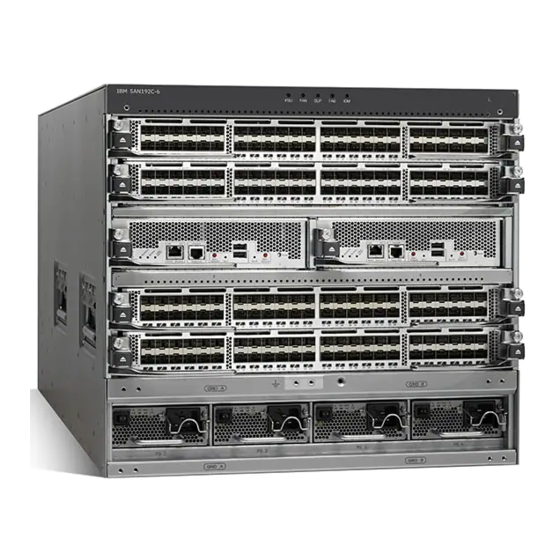
Multiple protocol support, including Fibre Channel. IBM SAN192C-6 Key features for the IBM SAN192C-6 device. The SAN192C-6 is designed for deployment in small- to medium-sized storage networks that can support enterprise clouds and business transformation. The SAN192C-6 includes the following components:... -
Page 27: Supported Components
A 48 Port 32 Gbps Fibre Channel Switching Module v A 24/10 port SAN Extension module The SAN192C-6 supports up to 192 ports in a 6-slot modular chassis, with up to 768 ports in a single rack. The ports can be configured as Fibre Channel (2/8/4 Gbps, 4/8/16 Gbps, or 8/16/32 Gbps). -
Page 28: Supported Components On The San192C-6
The SAN192C-6 director supports the following components: v SAN192C-6 Chassis IBM c-type SAN Director Supervisor-1 module IBM c-type SAN Director 48 Port 32 Gbps Fibre Channel Switching Module IBM c-type SAN Director 24/10 port SAN Extension module v SAN192C-6 Crossbar Switching Fabric1 Module... -
Page 29: San768C-6 Chassis Front View
Figure 1. SAN768C-6 Chassis Front View I/O modules (slots 1-8 and 11-18) Supervisor modules (slots 9 and 10) Power supplies (16 bays) Chassis mounting brackets Chassis handles System LEDs Ground point Grid A PSU bays Chapter 1. Introducing the IBM c-type SAN Directors... -
Page 30: San768C-6 Chassis Rear View
Figure 2. SAN768C-6 Chassis Rear View 1. Fan module 2. Fabric modules 3. Fan module handle 4. Fan module exhaust 5. Fan power connector 6. Fan and Fabric LEDs 7. Ground point 8. PSU exhaust SAN192C-6, SAN384C-6 and SAN768C-6 Installation, Service, and User Guide... -
Page 31: San384C-6 Chassis
26 hold fabric modules 5 and 6. The slots for the fabric modules are behind the fan modules. Figure 3 on page 8 shows the front view of the SAN384C-6 chassis. Chapter 1. Introducing the IBM c-type SAN Directors... -
Page 32: San384C-6 Chassis Front View
Supervisor modules (1 to 2) Switching modules (5 to 8) Power supply modules 7. Handles used for adjusting the chassis placement Figure 4 on page 9 shows the rear view of the SAN384C-6 chassis. SAN192C-6, SAN384C-6 and SAN768C-6 Installation, Service, and User Guide... -
Page 33: San192C-6 Chassis
Telco rack, with mounting rails. SAN192C-6 Chassis The SAN192C-6 has a six-slot chassis that supports one or two supervisor modules, up to six fabric modules, three fan modules, and up to four AC or DC 3 kW power supplies. Airflow is front-to-back in the SAN192C-6 chassis. -
Page 34: San192C-6 Chassis Front View
Supervisor module (1 to 2) Power supply modules (up to 4) Handles used for adjusting the chassis placement Figure 6 on page 11 shows the rear view of the SAN192C-6 chassis. SAN192C-6, SAN384C-6 and SAN768C-6 Installation, Service, and User Guide... -
Page 35: System Leds
LEDs for fan module and fabric modules Handles used for adjusting the chassis placement Vertical mounting brackets System LEDs Table 2 describes the System LEDs for the IBM c-type SAN switches and directors. Table 2. IBM c-type SAN switches and directors System LEDs Status Description... -
Page 36: Supervisor Modules
Table 2. IBM c-type SAN switches and directors System LEDs (continued) Status Description Green Supervisor modules are operational. Amber At least one I/O module has a red STATUS LED. Green Fabric modules are operational. Amber At least one I/O module has a red STATUS LED. -
Page 37: Ibm Supervisor-1E Module
18. Management port operational status LED 19. Module ejection lever 20. Slot0 USB port Table 3 on page 14 describes the LEDs on the IBM c-type SAN switches and directors Supervisor-1E Module. Chapter 1. Introducing the IBM c-type SAN Directors... -
Page 38: Ibm Supervisor-1E Module Leds
At least one power supply has failed or the power supply fan has failed. The temperature of the supervisor module exceeded the major threshold. The slot has detected a slot ID parity error SAN192C-6, SAN384C-6 and SAN768C-6 Installation, Service, and User Guide... - Page 39 Do not remove the media until the LED is off. The expansion flash CompactFlash or USB disk is not being accessed. You can remove the media while this LED is off. Chapter 1. Introducing the IBM c-type SAN Directors...
-
Page 40: Ibm Supervisor-1 Module
IBM Supervisor-1 Module The IBM Supervisor-1 Module is designed specifically for the SAN192C-6 and SAN384C-6 chassis. This supervisor module provides control and management functions for the switch and enables high-performance switching. This supervisor module supports the following features: Nondisruptive software upgrades... -
Page 41: Ibm Supervisor-1 Module
17. PWR MGMT: system power status LED 18. Management port operational status LED 19. Module ejection lever 20. Slot0 USB port Table 4 describes the LEDs on the IBM c-type SAN switches and directors Supervisor-1 Module. Table 4. IBM Supervisor-1 Module LEDs Status... - Page 42 HA active state. Amber The supervisor module is in HA standby state. Power Management Green There is sufficient power available for all installed modules. Amber There is insufficient power for all installed modules. SAN192C-6, SAN384C-6 and SAN768C-6 Installation, Service, and User Guide...
-
Page 43: Crossbar Fabric Modules
Crossbar Fabric Modules This section describes the crossbar fabric modules supported by different IBM c-type SAN director switches: v “SAN768C-6 Crossbar Fabric Modules” on page 20 v “SAN384C-6 Crossbar Fabric Modules” on page 22 v “SAN192C-6 Crossbar Fabric Modules”... -
Page 44: San768C-6 Crossbar Fabric Modules
21 through 26, numbered from left to right, at the back of the chassis behind the fan modules. Figure 9. SAN768C-6 Crossbar Fabric Module 1. Locking lever 2. Unlocking button 3. Fabric module LEDs SAN192C-6, SAN384C-6 and SAN768C-6 Installation, Service, and User Guide... -
Page 45: San768C-6 Crossbar Modules Leds
The module is not receiving power. Locater ID Flashing Blue The operator has activated this LED to identify this module in the chassis. Operator has not flagged this card for identification. Chapter 1. Introducing the IBM c-type SAN Directors... -
Page 46: San384C-6 Crossbar Fabric Modules
A fourth crossbar fabric module is required for N+1 protection. Figure 10. SAN384C-6 Crossbar Fabric Module 1. Locking lever 2. Unlocking button 3. Fabric module LEDs 4. Connector pins SAN192C-6, SAN384C-6 and SAN768C-6 Installation, Service, and User Guide... -
Page 47: San384C-6 Crossbar Modules Leds
Operator has not flagged this card for identification. Since the crossbar fabric modules are located behind the fan modules in the chassis, the LEDs on the crossbar fabric module are not easily visible from the back Chapter 1. Introducing the IBM c-type SAN Directors... -
Page 48: San192C-6 Crossbar Fabric Modules
2 needs to be activated followed by the locator LED of fabric module SAN192C-6 Crossbar Fabric Modules The SAN192C-6 supports up to six crossbar fabric modules. There is a crossbar fabric module designed specifically for the SAN192C-6. The crossbar fabric modules are installed vertically at the back of the chassis behind the fan modules. -
Page 49: San192C-6 Crossbar Fabric Module
1. Locking lever 2. Unlocking button 3. Fabric module LEDs 4. Connector pins The LEDs on the crossbar fabric modules indicate the status of the modules. Table 7 on page 26 describes the LEDs. Chapter 1. Introducing the IBM c-type SAN Directors... -
Page 50: San192C-6 Crossbar Modules Leds
Since each fan module covers two fabric modules, the status LEDs for two crossbar fabric modules are present on each fan module. If the fan module is removed the status and locator LEDs on crossbar fabric modules will be visible. SAN192C-6, SAN384C-6 and SAN768C-6 Installation, Service, and User Guide... -
Page 51: Fibre Channel Switching Modules
IBM c-type SAN switches and directors switches. IBM 48 port 32 Gbps Fibre Channel Switching Module The IBM 48 port 32 Gbps Fibre Channel switching module is designed specifically for the IBM c-type SAN directors. With 768 line-rate 32 Gbps Fibre Channel ports per director, the 32 Gbps 48 port... -
Page 52: Leds On The 48 Port 32 Gbps Fibre Channel Switching Modules
LEDs on the 48 port 32 Gbps Fibre Channel Switching Modules Table 8 describes the LEDs for the 48 port 32 Gbps Fibre Channel switching module. Table 8. IBM 48 Port 32 Gbps Fibre Channel Switching Module LEDs Status Description Status Green All diagnostics pass. -
Page 53: San Extension Modules
IBM c-type SAN Switches and Directors Datasheet. Note: In NX-OS Release 7.3(0)DY(1), 40GE IP Storage interfaces are not supported. Figure 13 on page 30 shows a IBM c-type SAN Director 24/10 Port SAN Extension Module. Chapter 1. Introducing the IBM c-type SAN Directors... -
Page 54: Leds On The 24/10 Port San Extension Module
FCIP port group LEDs on the 24/10 Port SAN Extension Module Table 9 describes the LEDs for the 24/10 port SAN Extension module. Table 9. IBM c-type SAN switches and directors 24/10 Port SAN Extension Module LEDs Status Description SAN192C-6, SAN384C-6 and SAN768C-6 Installation, Service, and User Guide... - Page 55 Table 9. IBM c-type SAN switches and directors 24/10 Port SAN Extension Module LEDs (continued) Status Green All diagnostics pass. The module is operational (normal initialization sequence). Orange One of the following occurs or occurred: The module is booting or running diagnostics (normal initialization sequence).
-
Page 56: Fan Modules
Table 9. IBM c-type SAN switches and directors 24/10 Port SAN Extension Module LEDs (continued) Link Solid green Link is up. Steady Flashing Green Port Beacon On (beacon is used to identify port). Intermittent Flashing Green Link is up (traffic on port). -
Page 57: San384C-6 Fan Modules
3 and 4, and fan module 3 must be removed to access fabric modules 5 and 6. Figure 15 on page 34 shows the front and rear view of a SAN384C-6 fan module. Chapter 1. Introducing the IBM c-type SAN Directors... -
Page 58: San192C-6 Fan Modules
6. Fan module connectors SAN192C-6 Fan Modules The SAN192C-6 has three fan modules, each with two fans, that are installed vertically at the back of the chassis. Each fan module can be removed while the other two fan modules continue to move air through the chassis. -
Page 59: Power Supplies
5. Fans (4) 6. Fan module connectors Power Supplies The IBM c-type SAN switches and directors supports the following types of power supplies: v 3000 W AC power supply (AC input and DC output) v 3000 W DC power supply (DC input and DC output) The SAN768C-6 supports up to 16 hot-swappable 3000 W AC or DC power supplies. - Page 60 Note: The minimum number of AC PSUs required to achieve grid redundancy on each of the IBM c-type SAN switches and directors differ. For more information see the AC Power Supply Requirements for Grid Redundancy section. When PSUs are in 1450 W mode and the system is configured in redundant power mode, the total power available to the system may not be sufficient to power all modules installed in the chassis.
-
Page 61: Dc Power Supply
3. Positive terminals 4. Power module LEDs 5. Power supply handle 6. Power supply exhaust 7. Unlocking lever Table 10 describes the power supply LEDs for the IBM c-type SAN switches and directors. Table 10. Power Supply LEDs Status Description... -
Page 62: Power Modes
50% of the power supplies failing, as when a power grid fails. The system logically allocates the left two columns of PSU bays to Grid SAN192C-6, SAN384C-6 and SAN768C-6 Installation, Service, and User Guide... - Page 63 Figure 19 shows how to connect power supplies in a SAN768C-6 for grid redundancy Figure 19. SAN768C-6 Grid-PSU Connections Figure 20 on page 40 shows how to connect power supplies in a SAN384C-6 for grid redundancy Chapter 1. Introducing the IBM c-type SAN Directors...
-
Page 64: Supported Transceivers
Figure 20. SAN384C-6 Grid-PSU Connections Figure 21 shows how to connect power supplies in a SAN192C-6 for grid redundancy Figure 21. SAN192C-6 Grid-PSU Connections Supported Transceivers The SAN384C-6 supports the Fibre Channel SFP+ transceivers in either SWL or LWL. Fibre Channel SFP+ Transceivers The transceivers are field-replaceable and hot-swappable. -
Page 65: Chapter 2. Rack Installation
“Rack and Cabinet Requirements for the SAN768C-6 Chassis” on page 42 v “Rack and Cabinet Requirements for the SAN384C-6 Chassis” on page 42 v “Rack and Cabinet Requirements for the SAN192C-6 Chassis” on page 43 v “Clearance Requirements for IBM c-type SAN switches and directors” on page... -
Page 66: Rack And Cabinet Requirements For The San768C-6 Chassis
Work with your cabinet vendors to determine which of their cabinets meet the following requirements or see the IBM Support for recommendations: v The height of the rack or cabinet must accommodate the 25 RU (43.75 inches or... -
Page 67: Rack And Cabinet Requirements For The San192C-6 Chassis
Work with your cabinet vendors to determine which of their cabinets meet the following requirements or see the IBM Support for recommendations: v The height of the rack or cabinet must accommodate the 9 RU (15.75 inches or... -
Page 68: Clearance Requirements For Ibm C-Type San Switches And Directors (Top View)
Figure 22. Clearance Requirements for IBM c-type SAN switches and directors (Top View) 1. Chassis 2. Cable Management Frames 3. Vertical rack-mount posts and rails 4. Area used for fan tray handles at the rear of the chassis (allow 2 inches [5 cm]) 5. -
Page 69: Rack-Mounting Guidelines
Before Installing the Rack-Mount Support Brackets Before installing the rack-mount support brackets for the IBM c-type SAN switches and directors, check the contents of your kit. Table 11 lists the contents of the shelf bracket kit. -
Page 70: Installing The Ibm C-Type San Director Shelf Bracket Kit Into A Rack
Installing the IBM c-type SAN Director Shelf Bracket Kit into a Rack About this task Figure 23 shows the installation of the IBM c-type SAN Director Shelf Bracket Kit into a four-post rack. Figure 23. Installing the Shelf Bracket Kit into a Rack Use this procedure to install the shelf brackets in a rack. - Page 71 For detailed information about the items required for installation, see the “Required Equipment” on page 45. The IBM c-type SAN Director Shelf Bracket Kit can be used to support the switch in a non-threaded rack. This shelf bracket kit can be used as a permanent support when installing a IBM c-type SAN Director in a rack that meets the requirements listed in the “Rack Requirements”...
- Page 72 Removing the Shelf Bracket Kit About this task The shelf bracket kit can be removed after the IBM c-type SAN director switch has been installed in a two-post telco (only SAN192C-6 Director) or four-post EIA rack, and the front rack-mount brackets are securely attached to the rack-mounting rails.
-
Page 73: Chapter 3. Installing The Ibm C-Type San Device
Chapter 3. Installing the IBM c-type SAN Device This chapter describes how to install the IBM c-type SAN Device chassis and its components, and includes the following information: v “Attaching Bottom-Support Rails to a Four-Post Rack” on page 53 v “Attaching Bottom-Support Rails to a Four-Post Rack” on page 53 v “Attaching Bottom-Support Rails to a Two-Post Rack for the SAN192C-6... -
Page 74: Unpacking And Inspecting The Switch
1 or 2 supervisor modules v 1 to 4, 8, or 16 switching modules depending on the IBM c-type SAN Device v Up to six crossbar fabric modules... -
Page 75: Required Equipment
IBM c-type SAN Device to proper grounding facilities. Crimping tool large enough to accommodate girth of the DC lug Wire-stripping tool v For the IBM c-type SAN Device, you need a mechanical lift to handle the weight of the fully-loaded chassis. Installation Guidelines Follow these guidelines when installing the IBM c-type SAN Device. -
Page 76: Attaching Bottom-Support Rails To A Two-Post Rack For The San192C-6 Director
M6 screws: 20 in-lb v 12-24 screws: 30 in-lb v 10-20 screws: 22 in-lb Attaching Bottom-Support Rails to a Two-Post Rack for the SAN192C-6 Director Use this procedure to attach the bottom support rails to a two-post rack for the SAN192C-6 Director. -
Page 77: Attaching Bottom-Support Rails To A Four-Post Rack
If any other devices are stored in the rack or cabinet, verify that they are located below where you plan to install the switch. Also, verify that lighter devices in the same rack are located above where you plan to install this switch. Chapter 3. Installing the IBM c-type SAN Device... - Page 78 9 RU of vertical space above the rails to install the chassis. You can expand the rail so that its mounting brackets are spaced between 24 to 32 inches (61.0 to 81.3 cm). SAN192C-6, SAN384C-6 and SAN768C-6 Installation, Service, and User Guide...
-
Page 79: Positioning Bottom-Support Rail - San384C-6 Chassis
Figure 25. Positioning Bottom-Support Rail - SAN384C-6 Chassis 1. Position two bottom-support rails at the lowest RU on the rack. 2. Allow at least 24.5 inches (62.2 cm) (14 RU) for each chassis. Chapter 3. Installing the IBM c-type SAN Device... -
Page 80: Positioning Bottom-Support Rail - San768C-6 Chassis
(using a total of 6 to 8 screws for the rail as shown Figure 27 on page 57 ) and tighten each screw to 40 in. lbs (4.5 N.m) of torque. SAN192C-6, SAN384C-6 and SAN768C-6 Installation, Service, and User Guide... -
Page 81: Attaching Bottom-Support Rails To A Rack - San384C-6 Chassis
When the bottom-support rails are installed at the lowest possible RU and are level, you are ready to install the chassis in the rack or cabinet. Chapter 3. Installing the IBM c-type SAN Device... -
Page 82: Installing The San192C-6 Chassis In A Two-Post Rack
– Mechanical lift capable of lifting the full weight of the chassis and its installed modules Note: Fully loaded, the SAN192C-6 chassis can weigh up to 325 lb (147.5 kg). You can lighten the chassis for easier moving by removing its power supplies, fan modules, and fabric modules. - Page 83 4. Push the chassis halfway onto the rack or cabinet. Use two persons to push the chassis onto the bottom-support rails. Push the lower half of the front side of the chassis so that the back side enters the rack Chapter 3. Installing the IBM c-type SAN Device...
-
Page 84: Moving A Chassis Onto A Rack Or Cabinet
7. Use seven M6 x 19 mm or 24 x 3/4-inch screws to attach each of the two vertical mounting brackets on the chassis to the two vertical mounting rails on the rack (total of 14 screws). See Figure 30 on page 61. SAN192C-6, SAN384C-6 and SAN768C-6 Installation, Service, and User Guide... -
Page 85: Attaching The Chassis To The Rack
Rotate the levers away from the front of the module and hold them while sliding the module all the way into the slot. f. Simultaneously rotate both levers to the front of the module. They click when locked to the front of the module. Chapter 3. Installing the IBM c-type SAN Device... -
Page 86: Installing The San384C-6 Or San768C-6 Device On A Four-Post Rack Or Cabinet
Note: Stability hazard. The rack stabilizing mechanism must be in place, or the rack must be bolted to the floor before you slide the unit out for servicing. Failure to stabilize the rack can cause the rack to tip over. SAN192C-6, SAN384C-6 and SAN768C-6 Installation, Service, and User Guide... - Page 87 When connected to 220 VAC, the 3000-W AC power supplies DS-CAC97-3KW for the IBM c-type SAN Device are designed to provide an output power of 3000 W to power the modules and fans. When connected to a 110 VAC power system, the power supply provides approximately 1450 W.
- Page 88 If the rack is provided with stabilizing devices, install the stabilizers before mounting or servicing the unit in the rack About this task Use this procedure to install the IBM SAN384C-6 or SAN768C-6 device on a Four-Post Rack or Cabinet. Procedure 1.
- Page 89 1/4 inch (0.6 cm) above the rails. Note: The IBM c-type SAN Device has the front-to-back cold-aisle and hot-aisle air flow design. We recommend that you maintain a minimum air space of 7 inches (30.5 cm) at the chassis front and back air vents.
-
Page 90: Chassis Onto A Rack Or Cabinet - San384C-6 Chassis
Figure 31. Chassis onto a Rack or Cabinet - SAN384C-6 Chassis 1. Push the sides of the lower half of the front side of the chassis. 2. Chassis mounting brackets. 3. Rack vertical mounting rails. SAN192C-6, SAN384C-6 and SAN768C-6 Installation, Service, and User Guide... -
Page 91: Moving A Chassis Onto A Rack Or Cabinet - San768C-6 Chassis
1/4 inch (0.6 cm) below the rails. This action helps to prevent the bottom of the chassis from getting caught on the bottom expansion edges of the bottom-support rails. Chapter 3. Installing the IBM c-type SAN Device... -
Page 92: Attaching The Chassis To The Two Vertical The Chassis To The Rack - San384C-6 Chassis
1. Handles used to adjust the chassis placement 2. Seven M6 x 19 mm or 10-24 x 3/4 in. Phillips screws used to attach each side bracket to a front mounting rail (use a total of 12 screws) SAN192C-6, SAN384C-6 and SAN768C-6 Installation, Service, and User Guide... -
Page 93: Attaching The Chassis To The Rack - San768C-6 Chassis
The electrical connectors will be at the bottom. b. Align the rear of the fabric module to an open fabric slot and insert the bracket on top of the module into the track at the top of the slot. Chapter 3. Installing the IBM c-type SAN Device... - Page 94 Release the middle handle. Note: v The lever should grab the inside of the slot and push the power supply onto its mid-plane connectors. SAN192C-6, SAN384C-6 and SAN768C-6 Installation, Service, and User Guide...
-
Page 95: System Grounding
Commercial building Medium to high Appropriate grounding contains a mix of information practices must be closely technology equipment and followed. industrial equipment, such as welding. Chapter 3. Installing the IBM c-type SAN Device... -
Page 96: Preventing Electrostatic Discharge Damage
Always wear an ESD wrist strap and ensure that it makes maximum contact with bare skin. ESD grounding straps are available with banana plugs, metal spring clips, or alligator clips. All IBM c-type SAN devices are equipped with a banana plug connector (identified by the ground symbol next to the connector) - Page 97 (NEBS) ground. If you are installing the system (NEBS) ground on models of the IBM c-type SAN Device chassis that are equipped with either AC-input or DC-input power supplies, you do not need to power down the chassis.
- Page 98 If you are using an ESD wrist strap that is equipped with an alligator clip, attach the alligator clip directly over the head of the system ground lug screw or to the system ground lug barrel. c. Follow these additional guidelines when handling modules: SAN192C-6, SAN384C-6 and SAN768C-6 Installation, Service, and User Guide...
-
Page 99: Installing, Removing And Verifying Field Replaceable Units
If both levers are released, the system has disconnected and powered down the module, and the STATUS LED will be unlit. To reconnect and power up the module, either remove and reinsert Chapter 3. Installing the IBM c-type SAN Device... -
Page 100: Installing Supervisor Modules
Note: You need a flat-blade or number 2 Phillips-head screwdriver to loosen or tighten the captive screw on the supervisor module. Use this procedure to install a supervisor module on a IBM c-type SAN Device. Procedure 1. Before installing any modules in the chassis, we recommend that you install the chassis in the rack. -
Page 101: Installing A Switching Module
To remove a currently installed module, see the “Removing a Switching Module” on page 78. 6. Press line card ejector buttons to open both side levers to fully open position. Chapter 3. Installing the IBM c-type SAN Device... -
Page 102: Removing A Switching Module
7. Place the module on an antistatic mat or antistatic foam, or immediately reinstall it in another slot. 8. If the slot will remain empty, install a filler panel to keep the chassis dust-free and to maintain proper airflow through the chassis. SAN192C-6, SAN384C-6 and SAN768C-6 Installation, Service, and User Guide... -
Page 103: Verifying Installation Of The Supervisor And Switching Modules
1, 2, 3, 4, 5, and 6 Installing a Crossbar Fabric Module About this task To install a crossbar module in the IBM c-type SAN Device, follow these steps: Procedure 1. Before installing any modules, install at least one Supervisor-1 module. - Page 104 “Installing and Removing Fan Modules” on page Removing a Crossbar Fabric Module About this task To remove a crossbar module from the IBM c-type SAN Device without compromising the integrity and availability of SANs, follow these steps: Procedure 1.
-
Page 105: Installing And Removing A Power Supply
Note: Power supply captive installation screws must be tight to ensure protective grounding continuity. CAUTION: Each AC power supply for the IBM c-type SAN Device weighs 6 lb (2.7 kg). CAUTION: Each DC power supply for the IBM c-type SAN Device weighs 11 lb (5 kg). -
Page 106: Operating. Use Caution When Servicing
Note: Hazardous voltage or energy is present on the backplane when the system is operating. Use caution when servicing. To install a DC power supply in the IBM c-type SAN Device, follow these steps: Procedure 1. Ensure that all power is off by locating the circuit breaker on the panel board that services the DC circuit. - Page 107 Note: The terminal box has four slots for four power terminals (ordered as negative [-], positive [+], positive [+], and negative [-]). Each terminal has two nuts that you use to fasten a power cable to the terminal. Chapter 3. Installing the IBM c-type SAN Device...
-
Page 108: Removing The Safety Cover For The Terminal Box On The 3-Kw Dc Power Supply
7. For the powered down circuits connected to the power supplies, turn on the power at the circuit breaker. The Input 1 (IN1) and Input 2 (IN2) LEDs turn on each connected power supply. SAN192C-6, SAN384C-6 and SAN768C-6 Installation, Service, and User Guide... - Page 109 (from 0 to 1 as labeled on the power switch for each power supply). The LEDs should flash and then the Output LED should turn on in addition to the Input LEDs. If the FAULT LED is lit or flashing, call IBM Support for assistance.
-
Page 110: Installing And Removing Fan Modules
The IBM c-type SAN Devices have three fan modules. Each fan module for the SAN384C-6 Director has four individual fans and each fan module for the... -
Page 111: Starting Up The Switch
Let the fan blades completely stop before you remove the fan module. To remove the fan module from the IBM c-type SAN Device, follow these steps: Procedure 1. Loosen the four captive screws on the module being removed. -
Page 112: Powering Up The Switch
CAUTION: Do not operate the switch without a functioning fan module except during the brief fan module replacement procedure. The IBM c-type SAN switches and devices can operate for only a few minutes without a functioning fan module before they begin to overheat. - Page 113 For instructions about how to configure the switch and check module connectivity, see the Cisco NX-OS Fundamentals Configuration Guide or the Cisco Fundamentals Configuration Guide for DCNM SAN.. Chapter 3. Installing the IBM c-type SAN Device...
- Page 114 SAN192C-6, SAN384C-6 and SAN768C-6 Installation, Service, and User Guide...
-
Page 115: Chapter 4. Connecting The Ibm C-Type San Director
When running power and data cables in overhead or sub floor cable trays, we strongly recommend that power cables and other potential noise sources be located as far away as is practical from network cabling that terminates on IBM equipment. In situations where long parallel cable runs cannot be separated by at least 3.3 ft (1 m), we recommend shielding any potential noise sources by... -
Page 116: Connecting To The Mgmt 10/100/1000 Ethernet Port
Use a modular, RJ-45, straight-through UTP cable to connect the MGMT 10/100/1000 Ethernet port to an Ethernet switch port or hub. Use a cross-over cable to connect to a router interface. SAN192C-6, SAN384C-6 and SAN768C-6 Installation, Service, and User Guide... -
Page 117: Connecting To A Fibre Channel Port
We recommend disconnecting cables before installing or removing these transceivers to prevent damage to the cable or transceiver. Note: Use only Cisco SFP+ or QSFP+ transceivers on the IBM c-type SAN switches and directors. Each SFP+ or QSFP+ transceiver is encoded with model information that enables the switch to verify that the SFP+ or QSFP+ transceiver meets the requirements for the switch. -
Page 118: Sfp+ Transceiver With Mylar Tab Latch
If the transceiver has a bale clasp latch, open the clasp by pressing it downwards, and then pull the transceiver out of the port. SAN192C-6, SAN384C-6 and SAN768C-6 Installation, Service, and User Guide... -
Page 119: Alternate Removal Method For Bale Clasp Sfp+ Or Qsfp+ Transceivers
Note: If you cannot install the cable into the transceiver, insert or leave the dust plug in the cable end of the transceiver. Chapter 4. Connecting the IBM c-type SAN Director... - Page 120 3. Remove the dust cover from the cable end of the transceiver. 4. Align the cable connector with the transceiver and insert the connector into the transceiver until it clicks into place (see Figure 39 on page 97). SAN192C-6, SAN384C-6 and SAN768C-6 Installation, Service, and User Guide...
-
Page 121: Maintaining Sfp+ And Qsfp+ Transceivers And Fiber-Optic Cables
Inspect routinely for dust and damage. If damage is suspected, clean and then inspect fiber ends under a microscope to determine if damage has occurred. Chapter 4. Connecting the IBM c-type SAN Director... - Page 122 SAN192C-6, SAN384C-6 and SAN768C-6 Installation, Service, and User Guide...
-
Page 123: Appendix A. Product Specifications
This appendix provides technical specifications and includes the following sections: v “Switch Specifications” v “Power Specifications for the IBM c-type SAN Director” on page 102 v “SFP+ Transceiver Specifications” on page 107 Note: Specifications for cables and connectors are provided in Appendix B, “Cable and Port Specifications,”... -
Page 124: San384C-6 Director Specification
160 cubic feet per minute (CFM) total flow through each line-card slot depending on the line-card type and fan-speed setting SAN192C-6 Director Specification Table 17 lists the physical specifications for the SAN192C-6 Director. Table 17. Specifications for the SAN192C-6 Director Description Specification Dimensions (HxWxD) 9 rack units (9 RU) 15.6 x 17.3 x 32.0 in. -
Page 125: Supervisor-1E Module Specifications
Table 19. Supervisor-1E Module Specifications Description Specification Environmental Requirements Temperature, certified for operation (module 32 to 104° F (0 to 40° C) intake of ambient) Temperature, ambient nonoperating and -40 to 158° F (-40 to 70° C) storage Humidity (RH), ambient (noncondensing) 10 to 90% operating Altitude, designed and tested for operation... -
Page 126: Power Specifications For The Ibm C-Type San Director
1.75 x 15.9 x 21.8 in. (4.4 x 40.39 x 55.37 cm) Weight 17 lb (7.7 kg) Table 22 lists the specifications for the IBM c-type SAN Director 48-Port 32-Gbps FC Switching Module. Table 22. IBM c-type SAN Director 48-Port 32-Gbps Fibre Channel Switching... -
Page 127: Component Power Requirements And Heat Dissipation
3500 W maximum (220 to 380 VDC) Component Power Requirements and Heat Dissipation When sizing the air-conditioning requirements for an installation, consider heat dissipation. The power and heat associated with an IBM SAN c-type Directors varies based upon the following considerations: Power supply type... -
Page 128: Requirements For 3000 W Ac Power
Module SAN192C-6 Fan Module Table 25. Dissipation for 3000 W AC Power Supplies for Different Solutions with 32-G Fibre Channel ports using IBM c-type SAN Director 48 port 32Gbps Switching Module and six Fabric Modules. Power Required (watts) Number of... -
Page 129: Ac Power Consumption For The San768C-6 Director
Table 25. Dissipation for 3000 W AC Power Supplies for Different Solutions with 32-G Fibre Channel ports using IBM c-type SAN Director 48 port 32Gbps Switching Module and six Fabric Modules. (continued) Power Required (watts) Number of Heat Switching Number of... -
Page 130: Ac Power Consumption For The San192C-6 Director
AC Power Consumption for the SAN192C-6 Director Table 28 shows the typical AC power consumption for the SAN192C-6 Director. Table 28. Consumption for SAN192C-6 Director Typical AC Power Consumption (Watts) Number of Fabric Speed/Module Type Modules 96 ports 192 ports... -
Page 131: Sfp+ Transceiver Specifications
Module SFP+ Transceiver Specifications The IBM SAN c-type Directors are compatible with SFP+ transceivers and cables that have LC connectors. The wavelength of each transceiver must match the transceiver on the other end of the cable, and the cable must not exceed the stipulated cable length for reliable communications. -
Page 132: General Specifications For 32 Gbps Fibre Channel Sfp+ Transceivers
50.0 14.025 410 ft (125m) (OM5) 62.5 69 ft (21m) (OM1) 50.0 164 ft (50m) (OM2) 50.0 492 ft (150m) (OM3) 50.0 623 ft (190m) (OM4) 50.0 623 ft (190m) (OM5) SAN192C-6, SAN384C-6 and SAN768C-6 Installation, Service, and User Guide... -
Page 133: Specification For 32 Gbps Fibre Channel Sfp+ Transceivers
40° C 0° C 70° C -40° C For information about safety, regulatory, and standards compliance, refer to IBM Systems Safety Notices. General Specifications for 16 Gbps Fibre Channel SFP+ Transceivers Table 34 on page 110 provides the general specifications for Fibre Channel SFP+ transceivers. -
Page 134: General Specifications For 16 Gbps Fibre Channel Sfp+ Transceivers
-5.0 -10.0 7.8 (4 Gbps) 10km 6.4 (8 Gbps) LW SFP+ 6.4 (16 Gbps) Table 36 on page 111 provides the environment specification for the 16 Gbps Fibre Channel SFP+ transceivers. SAN192C-6, SAN384C-6 and SAN768C-6 Installation, Service, and User Guide... -
Page 135: Environmental Specifications For 16 Gbps Fibre Channel Sfp+ Transceivers
40° C 0° C 85° C -40° C For information about safety, regulatory, and standards compliance, refer to IBM Systems Safety Notices. General Specifications for 8 Gbps Fibre Channel SFP+ Transceivers Table 37 provides the general specifications for Fibre Channel SFP+ transceivers. -
Page 136: Maximum Environmental And Electrical Ratings For Fibre Channel Sfp+ Transceivers
40° C 0° C 85° C -40° C For information about safety, regulatory, and standards compliance, refer to IBM Systems Safety Notices. Maximum Environmental and Electrical Ratings for Fibre Channel SFP+ Transceivers Table 40 provides the maximum environmental and electrical ratings for Fibre Channel SFP+ transceivers. -
Page 137: Appendix B. Cable And Port Specifications
RJ-45F PC terminal adapter to connect the console port to a computer running terminal emulation software. Console Port Pinouts Table 41 lists the pinouts for the console port on the IBM c-type director. Table 41. Console Port Pinouts Signal Connecting the Console Port to a Computer Using the DB-25... -
Page 138: Mgmt 10/100/1000 Ethernet Port
(MDI) cable. Note: The RJ-45 interface only uses pins 1, 2, 3, and 6. Table 43. 10/100/1000BASE-T Management Port Cable Pinout (MDI) Signal RDû Not used Not used Not used SAN192C-6, SAN384C-6 and SAN768C-6 Installation, Service, and User Guide... -
Page 139: Supported Power Cords And Plugs
Orders delivered to Argentina, Brazil, and Japan must have the appropriate power cord ordered with the system. Table 44 lists the power cords for the IBM c-type Directors and provides their lengths in feet and meters. Table 44. Power Cords for the IBM c-type Director... -
Page 140: Supported Plugs For 3000 W Ac Power Supplies
South Africa (3000 W) EL 208, SABS 164-1 (16 A) Figure 43 on page 117 shows an additional plug that is supported for the 3000 W and 2500 W power supply, using 110 VAC. SAN192C-6, SAN384C-6 and SAN768C-6 Installation, Service, and User Guide... -
Page 141: Power Supply Ac Power Cords
Note: Using the plug in Figure 43 at 110 VAC results in 1450 W available to the system. Figure 43. Additional Power Supply Plug Supported for 3000 W 110 VAC Only NEMA 5-20P North American power cord product ID: CAB-7513AC 110 VAC (20 A) Power Supply AC Power Cords Table 45 lists the specifications for the 3000 W AC power cords that are available... - Page 142 Figure 44. AJK5 Figure 45. AJJX Figure 46. AJK4 SAN192C-6, SAN384C-6 and SAN768C-6 Installation, Service, and User Guide...
- Page 143 Figure 47. AJK2 Figure 48. AJK1 Figure 49. AJJY Appendix B. Cable and Port Specifications...
- Page 144 Figure 50. AJJV SAN192C-6, SAN384C-6 and SAN768C-6 Installation, Service, and User Guide...
-
Page 145: Appendix C. Site Planning And Maintenance Records
Finding the Chassis Serial Number You can find the chassis serial number label of the IBM c-type SAN switches and directors on the chassis. If you have CLI access, enter the show sprom backplane 1 command to display the backplane contents, including the switch serial number. - Page 146 SAN192C-6, SAN384C-6 and SAN768C-6 Installation, Service, and User Guide...
-
Page 147: Appendix D. Ibm C-Type San Director Accessory Kit Contents
Appendix D. IBM c-type SAN Director Accessory Kit Contents This appendix lists and illustrates the IBM c-type SAN Director accessory kit contents. (See Table 46) Table 46. IBM c-type SAN Director Accessory Kit Contents Illustration Description Quantity Support rack-mount bracket... - Page 148 Hazardous Substances Content Table Note: If you do not receive any part listed in this document, contact IBM Support. If you purchased this product through an IBM Business Partner, you may receive additional contents in your kit, such as documentation, hardware, and power cables.
-
Page 149: Notices
The materials at those web sites are not part of the materials for this IBM product and use of those web sites is at your own risk. -
Page 150: Trademarks
International Business Machines Corp., registered in many jurisdictions worldwide. Other product and service names might be trademarks of IBM or other companies. A current list of IBM trademarks is available on the web at Copyright and trademark information atwww.ibm.com/legal/copytrade.shtml Adobe, the Adobe logo, PostScript, and the PostScript logo are either registered trademarks or trademarks of Adobe Systems Incorporated in the United States, and/or other countries. -
Page 151: Industry Canada Compliance Statement
Properly shielded and grounded cables and connectors must be used in order to meet FCC emission limits. IBM is not responsible for any radio or television interference caused by using other than recommended cables and connectors, or by unauthorized changes or modifications to this equipment. -
Page 152: Germany Electromagnetic Compatibility Directive
/ EN 55032 Klasse A ein. Um dieses sicherzustellen, sind die Geräte wie in den Handbüchern beschrieben zu installieren und zu betreiben. Des Weiteren dürfen auch nur von der IBM empfohlene Kabel angeschlossen werden. IBM übernimmt keine Verantwortung für die Einhaltung der Schutzanforderungen, wenn das Produkt ohne Zustimmung von IBM verändert bzw. - Page 153 EN 55032 Klasse B ein. Um dieses sicherzustellen, sind die Geräte wie in den Handbüchern beschrieben zu installieren und zu betreiben. Des Weiteren dürfen auch nur von der IBM empfohlene Kabel angeschlossen werden. IBM übernimmt keine Verantwortung für die Einhaltung der Schutzanforderungen, wenn das Produkt ohne Zustimmung von IBM verändert bzw.
-
Page 154: People's Republic Of China Class A Statement
IBM Taiwan Corporation 3F, No 7, Song Ren Rd., Taipei Taiwan Tel: 0800-016-888 Japan Voluntary Control Council for Interference Class A Statement This explains the Japan Voluntary Control Council for Interference (VCCI) statement. SAN192C-6, SAN384C-6 and SAN768C-6 Installation, Service, and User Guide... -
Page 155: Japan Electronics And Information Technology Industries Association Statement
Japan Electronics and Information Technology Industries Association Statement This statement explains the Japan JIS C 61000-3-2 product wattage compliance. This statement explains the Japan Electronics and Information Technology Industries Association (JEITA) statement for products less than or equal to 20 A per phase. -
Page 156: Russia Electromagnetic Interference Class A Statement
Russia Electromagnetic Interference Class A Statement This statement explains the Russia Electromagnetic Interference (EMI) statement. SAN192C-6, SAN384C-6 and SAN768C-6 Installation, Service, and User Guide... -
Page 157: Index
Fabric OS version xxi rack getting help ix safety precautions xviii rack relocation safety xx read this first ix help ix safety notices xi rack installation xviii address x rack relocation xx notices 125 © Copyright IBM Corp. 2018... - Page 158 SAN192C-6, SAN384C-6 and SAN768C-6 Installation, Service, and User Guide...
- Page 160 IBM® Part Number: 02JD693 Printed in USA SC27-9276-00...
Need help?
Do you have a question about the SAN192C-6 and is the answer not in the manual?
Questions and answers