
Related Manuals for IBM SAN42B-R


Summary of Contents for IBM SAN42B-R
- Page 1 IBM System Storage SAN42B-R Installation, Service, and User Guide MTM Service information: 2498-R42 SC27-6633-00...
- Page 3 IBM System Storage SAN42B-R Installation, Service, and User Guide MTM Service information: 2498-R42 SC27-6633-00...
- Page 4 Before you use the information in this publication, be sure to read the general information under “Notices” on page 61. Copyright Portions Copyright © 2014 Brocade Communications Systems, Inc. All Rights Reserved. © Copyright IBM Corporation 2014. US Government Users Restricted Rights – Use, duplication or disclosure restricted by GSA ADP Schedule Contract with IBM Corp.
-
Page 5: Table Of Contents
. 33 Getting help . . ix Interpreting POST results . . 37 Accessibility features for the SAN42B-R . . ix Switch maintenance . 37 How to send your comments . Chapter 4. FRU replacement ..39 Safety and environmental notices . - Page 6 SAN42B-R Installation, Service, and User Guide...
-
Page 7: Figures
Figures Port side view of the SAN42B-R . Attaching the rear brackets to the extensions at Port numbering in the switch . the front of the switch . . 20 Nonport side of the switch . Attaching the short or long rear brackets to the Power supply and fan details . - Page 8 SAN42B-R Installation, Service, and User Guide...
-
Page 9: Tables
Tables Sample caution notices . xiv Switch dimensions . . 51 Brocade and IBM product and model number Environmental requirements . . 51 matrix . . xxii Power supply specifications . . 52 WAN throughput licensing. Power consumption per chassis (typical Management options for the SAN42B-R configuration) . - Page 10 SAN42B-R Installation, Service, and User Guide...
-
Page 11: Read This First
For redbooks associated with this product, enter search terms on the following Web site: www.redbook.ibm.com. For support information for this and other IBM products, see the IBM Support Portal www.ibm.com/supportportal. Search for the product Machine type or product name. -
Page 12: How To Send Your Comments
Department GZW 9000 South Rita Road Tucson, Arizona 85744-0001 USA When you send information to IBM, you grant IBM a nonexclusive right to use or distribute the information in any way it believes appropriate without incurring any obligation to you. -
Page 13: Safety And Environmental Notices
Safety Notices publication that is shipped with this product. The following notices and statements are used in IBM documents. They are listed below in order of increasing severity of potential hazards. Follow the links for more detailed descriptions and examples of the danger, caution, and attention notices in the sections that follow. - Page 14 (D004) A general electrical danger notice provides instructions on how to avoid shock hazards when servicing equipment. Unless instructed otherwise, follow the procedures in the following danger notice. SAN42B-R Installation, Service, and User Guide...
- Page 15 Electrical voltage and current from power, telephone, and communication cables are hazardous. To avoid a shock hazard: v Connect power to this unit only with the IBM provided power cord. Do not use the IBM provided power cord for any other product.
-
Page 16: Caution Notices
Repair or disassemble Exchange only with the IBM-approved part. Recycle or discard the battery as instructed by local regulations. In the United States, IBM has a process for the collection of this battery. For information, call 1-800-426-4333. Have the IBM part number for the battery unit available when you call. -
Page 17: Safety Labels
CAUTION: The system contains circuit cards, assemblies, or both that contain lead solder. To avoid the release of lead (Pb) into the environment, do not burn. Discard the circuit card as instructed by local regulations. (C014) CAUTION: This product is equipped with a 3-wire (two conductors and ground) power cable and plug. -
Page 18: Attention Notices
Attention: Do not bend a fibre cable to a radius less than 5 cm (2 in.); you can damage the cable. Tie wraps are not recommended for optical cables because they can be easily overtightened and cause damage to the cable. SAN42B-R Installation, Service, and User Guide... -
Page 19: Esd Precautions
ESD precautions Attention: Many of the field replaceable units (FRUs) are sensitive to electrostatic discharge (ESD), and can potentially be damaged by improper handling. When working with any FRU, use correct ESD precautions: v Attach ground to the indicated area on the chassis v Wear a wrist grounding strap connected to the chassis ground (if the switch is plugged in) or a bench ground v Store ESD-sensitive components in antistatic packaging... - Page 20 Attempting to move the drawer partially or completely out of the rack might cause the rack to become unstable or cause the drawer to fall out of the rack. (R001 part 2 of 2) xviii SAN42B-R Installation, Service, and User Guide...
-
Page 21: Rack Relocation (19" Rack)
(R002) Product recycling and disposal Refer to the IBM Systems Environmental Notices and User Guide (Z125-5823) for translated environmental statements and information regarding product recycling and disposal. This document may be provided either in printed version or on the product documentation CD. - Page 22 SAN42B-R Installation, Service, and User Guide...
-
Page 23: About This Document
This document is intended for use by systems administrators and technicians experienced with networking, Fibre Channel, and storage area network (SAN) technologies. It describes how to install, service, and use the IBM System Storage SAN42B-R (machine type-model 2498-R42 switch). Throughout this document, the product is referred to as the SAN42B-R, or simply the switch. -
Page 24: Ibm And Brocade Product Matrix
(FOS) publications, you will notice that the model numbers reference the Brocade products. Table 2 provides a product matrix to correlate the Brocade products and models to the IBM product names and machine types and model numbers. Products withdrawn from marketing are not listed. -
Page 25: Chapter 1. Overview Of The San42B-R Switch
Chapter 1. Overview of the SAN42B-R switch The IBM System Storage SAN42B-R switch is intended as a platform for Fibre Channel over IP (FCIP). This enables transmission of Fibre Channel data over long distances by way of IP networks by wrapping Fibre Channel frames in IP packets. -
Page 26: Wan Throughput Licensing
Note: The application throughput numbers shown in the following table assume that some degree of data compression is occurring. However, IBM makes no promises, guarantees, or any indication that some level of compression is possible for customer-specific data. Some data is highly compressible and some data cannot be compressed. -
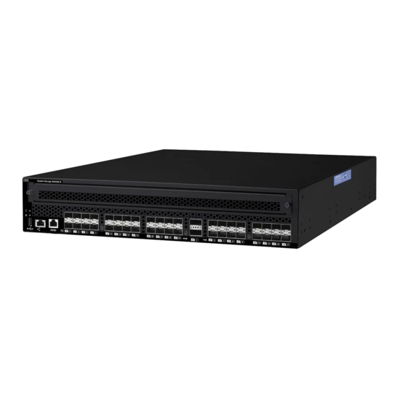
Page 27: Port Side Of The Switch
– The SAN42B-R uses common licenses with other midrange products (for example, SAN48B-5) for IR and CUP. – A new SKU for Advanced Acceleration for FICON license on the SAN42B-R is introduced v All ports and interfaces on the switch are active except for the 40 GE interfaces. -
Page 28: Nonport Side Of The Switch
Figure 1. Port side view of the SAN42B-R 1 - System status LED 2 - System power LED 3 - USB port 4 - Ethernet management port 5 - Console port (RJ-45) 6 - Serial number pull-out tab 7 - 16 GbE FC ports (24) -
Page 29: Switch Management
For information about upgrading the version of Fabric OS installed on your switch, see the “Getting help” on page ix and also see the Fabric OS Administrator's Guide. You can manage the switch using any of the management options listed in the following table. Chapter 1. Overview of the SAN42B-R switch... - Page 30 Table 4. Management options for the SAN42B-R Management tool Out-of-band support In-band support Command line interface Ethernet (preferred) or IP over Fibre Channel (CLI) console port connection Up to two admin sessions and four user sessions simultaneously. For more information, see...
-
Page 31: Chapter 2. Installing And Configuring The Switch
Chapter 2. Installing and configuring the switch You can install the SAN42B-R switch in the following ways: v As a stand-alone unit on a flat surface. For instructions and more information, see “Setting up the switch as a standalone unit” on page 10. - Page 32 Record port and cable connections using a table such as Appendix C, “Cable routing table,” on page 59. Items required for installation The following items are required for installing, configuring, and connecting the SAN42B-R for use in a network and fabric. SAN42B-R Installation, Service, and User Guide...
-
Page 33: Items Included With The Switch
Note: If any items are damaged or missing, within the United States and Canada, contact the IBM Quality Hotline toll-free 1-800-442-6773 or direct dial in other locations: 770-858-8459. v The SAN42B-R switch, containing two combined power supply FRUs with... -
Page 34: Setting Up The Switch As A Standalone Unit
Note: The illustrations in the installation instructions show a 1U device. The SAN42B-R is a 2U device but the installation instructions are the same. Attention: Refer to “Safety notices and labels” on page xi before starting any installation procedure. -
Page 35: Fixed Rack Mount Kit Parts List
Items required You need the following items to install the switch using the fixed rack mount kit: v Clamps or other means for temporarily supporting the switch in the cabinet v Phillips #2 torque screwdriver v 1/4 in. straight slot screwdriver v 2U of rack space v Fixed rack mount kit Attention: Use the screws specified for use with the switch. -
Page 36: Installation Instructions For Flush-Front Mounting
Attention: The switch must be turned off and disconnected from the fabric during this procedure. Note: The illustrations depict a 1U switch. The procedures and positioning are the same for the 2U high SAN42B-R. Attaching the front brackets Complete the following steps to attach the front brackets to the switch. See Figure 5 on page 11 for detailed illustrations of the parts. -
Page 37: Attaching The Bracket Extensions To The Switch
Attaching the bracket extensions to the switch Complete the following steps to attach the bracket extensions to the switch. See Figure 5 on page 11 for detailed illustrations of the parts. 1. Position the right bracket extension ( 1 ) along the side of the switch as shown in Figure 7. -
Page 38: Positioning The Switch In The Rack
15 (The long rear brackets are shown.) Use the third and fourth vertical pairs of holes for the screws. See Figure 10 on page 15 for more detail of the position of the short or long brackets and screws. SAN42B-R Installation, Service, and User Guide... - Page 39 Figure 9. Attaching the rear brackets to the extensions (long brackets shown) 1 - Rear brackets 2 - Screws, 6-32 x 1/4-in., panhead Phillips Figure 10. Rear bracket attachment details 1 - Rear brackets 2 - Screws, 6-32 x 1/4-in., panhead Phillips 3.
-
Page 40: Installation Procedure For Flush-Rear (Recessed) Mounting
Note: In this installation, the brackets are named as called out in Figure 5 on page 11 even though the installation of the brackets is reversed from the flush-front installation. Attention: The switch must be turned off and disconnected from the fabric during this procedure. SAN42B-R Installation, Service, and User Guide... -
Page 41: Attaching The Front Bracket
Note: The illustrations depict a 1U switch. The procedures and positioning are the same for the 2U high SAN42B-R. Attaching the front brackets Complete the following steps to attach the front brackets to the rear of the switch. See Figure 5 on page 11 for detailed illustrations of the parts. -
Page 42: Attaching The Extension Brackets To The Front Of The Switch
Figure 5 on page 11 for detailed illustrations of the parts. 1. Position the switch in the rack, as shown in Figure 14 on page 19, providing temporary support under the switch until the rail kit is secured to the rack. SAN42B-R Installation, Service, and User Guide... -
Page 43: Positioning The Switch Flush To The Rear Of The
Figure 14. Positioning the switch flush to the rear of the rack 1 - Screws, 10-32 x 5/8-in., panhead Phillips 2 - Retainer nuts, 10-32 2. Attach the right front bracket to the right rear rack post using two 10-32 x 5/8-in. -
Page 44: Attaching The Rear Brackets To The Extensions
3. Using the first and third vertical pairs of holes for the screws, attach the brackets with four 6-32 x 1/4-in. panhead screws ( 2 ). See Figure 16 Figure 16. Attaching the short or long rear brackets to the extensions 1 - Rear brackets (long brackets shown) SAN42B-R Installation, Service, and User Guide... -
Page 45: Initial Setup Of The Switch
2 - Screws, 6-32 x 1/4-in., panhead Phillips 4. Repeat steps 2-3 to attach the other rear bracket to the left extension. 5. Adjust the brackets to the rack depth and tighten all the 6-32 x 1/4-in. screws to a torque of 9 in-lbs (10 cm-kgs). Attaching the rear brackets to the front rack posts Complete the following steps to attach the rear brackets to the front rack posts. -
Page 46: Providing Power To The Switch
EZSwitchSetup to complete the basic configuration. See the EZSwitchSetup CD, included with the switch, for more information. You can also use the IBM System Storage SAN42B-R Quick Start Guide. If you do not want to use EZSwitch Setup, follow the instructions in this section. -
Page 47: Setting The Switch Ip Address
DANGER Multiple power cords. The product might be equipped with multiple power cords. To remove all hazardous voltages, disconnect all power cords. (L003) 3. After POST is complete, verify that the switch power and status LEDs on the left of the port side of the switch are both green. See “Port side of the switch” on page 3 for the specific location of these LEDs. - Page 48 Setting the domain ID of the switch Complete the following steps to set the switch domain ID. 1. Log in to the switch through Telnet using the admin account. 2. Modify the domain ID if required. SAN42B-R Installation, Service, and User Guide...
- Page 49 The default domain ID is 1. If the switch is not powered on until after it is connected to the fabric and the default domain ID is already in use, the domain ID for the new switch is automatically reset to a unique value. If the switch is connected to the fabric after it has been powered on and the default domain ID is already in use, the fabric segments.
- Page 50 UTC) Atlantic Standard -4,0 Atlantic Daylight -3,0 Eastern Standard -5,0 Eastern Daylight -4,0 Central Standard -6,0 Central Daylight -5,0 Mountain Standard -7,0 Mountain Daylight -6,0 Pacific Standard -8,0 Pacific Daylight -7,0 Alaskan Standard -9,0 SAN42B-R Installation, Service, and User Guide...
-
Page 51: Installing Sfp+ And Qsfp Transceivers And Connecting Cables
Attention: Use only transceivers that are supported for this product. Only transceivers purchased from IBM are supported. The use of transceivers that are not supported may cause data loss or cause the product to malfunction. For a listing of transceivers compatible with this product: v Go to the IBM Support Portal www.ibm.com/supportportal. - Page 52 Ensure that cables are properly seated within the connector. Kits are commercially available for cleaning and inspecting these connections. IBM also offers services that will ensure optimal condition of the network. Complete the following steps to install 16 Gbps SFP+ transceivers and cables.
-
Page 53: Verifying Correct Operation And Backing Up The Configuration
Figure 18. Installing a 16 Gbps SFP+ with pull tab (shown without cable attached for clarity) 5. Repeat steps 1-4 for the remaining SFP+ and QSFP transceivers and cables. Verifying correct operation and backing up the configuration Complete the following steps to verify correct operation and back up the switch configuration. - Page 54 This command uploads the switch configuration to the server, making it available for downloading to a replacement switch if necessary. IBM recommends backing up the configuration regularly to ensure that a complete configuration is available for downloading to a replacement switch. For specific...
- Page 55 Administrator's Guide. The switchShow, fabricShow, and configUpload commands are described in detail in the Fabric OS Command Reference. Chapter 2. Installing and configuring the switch...
- Page 56 SAN42B-R Installation, Service, and User Guide...
-
Page 57: Chapter 3. Using And Maintaining The Switch
Figure 19 shows the LEDs on port side of the switch. The port status LEDs for the FC ports are arranged left and right to correspond to the upper and lower ports respectively in each pair. Figure 19. LEDs on the port side of the switch 1 - System status LED © Copyright IBM Corp. 2014... -
Page 58: Port Side Led Patterns During Normal
Verify that the Ethernet cable is connected correctly. Steady green There is a link. No action required. Ethernet No light There is no link activity. No action required. Status/Activity Flashing green There is link activity (traffic). No action required. SAN42B-R Installation, Service, and User Guide... - Page 59 Table 6. Port side LED patterns during normal operation (continued) LED name LED color Status of hardware Recommended action FC port status No light Indicates one of the following: v Verify the power LED is on, and v No signal or light carrier (media or check the SFP and cable.
-
Page 60: Nonport Side Leds
Steady green Fan assembly is operating normally. No action required. Steady amber One or more of the fans in the fan Replace the faulty fan assembly. (for more than 5 assembly has failed. seconds) SAN42B-R Installation, Service, and User Guide... -
Page 61: Interpreting Post Results
Fabric OS Message Reference. Switch maintenance The SAN42B-R is designed for high availability and reliability; it does not require any regular physical maintenance. The switch includes diagnostic tests and field-replaceable units, described in the following sections. - Page 62 SAN42B-R Installation, Service, and User Guide...
-
Page 63: Chapter 4. Fru Replacement
Follow ESD precautions (see “ESD precautions” on page xvii whenever handling FRUs. The field replaceable units (FRUs) in the SAN42B-R can be removed and replaced without special tools. The switch can continue operating during the FRU replacement if the conditions specified in the procedures are followed. -
Page 64: Switch Power Supply Components
3. Push the locking tab ( 5 ) to the left and hold it there while using the handle ( 3 ) on the power supply to pull it straight out and away from the chassis. Pull the power supply out slowly to avoid catching a finger on the locking tab. SAN42B-R Installation, Service, and User Guide... -
Page 65: Fan Removal And Replacement
Figure 22. Removing and replacing a power supply in the switch 4. Slide the new power supply into the chassis until the locking tab engages. Attention: Do not force the installation. If the power supply does not slide in easily, ensure that the power supply is correctly oriented before continuing. 5. -
Page 66: Fan Components
Complete the following steps to replace a fan in the switch. Refer to Figure 23 and Figure 24 on page 43 for this procedure. 1. Using the Phillips screwdriver, unscrew the captive screw ( 3 in Figure 23) on the fan. SAN42B-R Installation, Service, and User Guide... -
Page 67: Chassis Replacement
Web Tools application. Chassis replacement The SAN42B-R chassis is highly reliable and unlikely to fail. However, the chassis is available as a FRU and can be replaced following these instructions. Chapter 4. FRU replacement... - Page 68 Determining the need to replace the chassis Before replacing the chassis, verify that the replacement is necessary. Ensure that the components are firmly seated when troubleshooting. Contact IBM if you have any questions about whether the chassis should be replaced. Any of the following...
- Page 69 Removing the power supplies from the chassis The two power supplies must be removed from the chassis; they will be installed in the new chassis. Refer to Figure 21 on page 40 and Figure 22 on page 41 to complete these steps to remove each power supply. 1.
-
Page 70: Removing The Battery
Repair or disassemble Exchange only with the IBM-approved part. Recycle or discard the battery as instructed by local regulations. In the United States, IBM has a process for the collection of this battery. For information, call 1-800-426-4333. Have the IBM part number for the battery unit available when you call. -
Page 71: Powercap Covering Battery
Figure 26. Powercap covering battery 6. Remove the battery from the holder. 7. Recycle the battery as appropriate, following local regulations. Refer to the Environmental Notices and User Guide shipped with the product for more information on battery recycling and disposal. Chapter 4. - Page 72 SAN42B-R Installation, Service, and User Guide...
-
Page 73: Appendix A. Product Specifications
Appendix A. Product specifications This appendix provides the specifications for the SAN42B-R switch. The SAN42B-R provides Fibre Channel, FICON, and FCIP performance for remote replication, backup, and migration. Up to 24 2/4/8/16 Gbps ports Fibre Channel ports, 16 1/10 GbE, and two 40 GbE optical ports support scalable bandwidth, port density, and throughput that extend Storage Area Network (SAN) fabric connectivity over distance. -
Page 74: Fibre Channel Specifications
10/100 Mbps Ethernet + LED specifications Table 12. LED types Component Description Switch status and management LEDs One power One system One per FC port One per Ethernet port Two for Ethernet management port SAN42B-R Installation, Service, and User Guide... -
Page 75: Switch Dimensions
Table 12. LED types (continued) Component Description Port status LEDs Color-changing LEDs to indicate status Weight and physical dimensions “Weight and physical dimensions” lists the dimensions and weight of the switch. A fully loaded switch includes all the fans and PSU FRUs, but not the tranceivers or cables. -
Page 76: Power Supply Specifications
490 W 1679 BTU/Hr 1672 BTU/Hr Ethernet port specifications Table 18. Ethernet port specifications Port type Number of ports Description 40 GbE Compatible with short range (SR) and long range (LR) optical QSFP+ transceivers SAN42B-R Installation, Service, and User Guide... -
Page 77: Fibre Channel Data Transmission Range
Table 18. Ethernet port specifications (continued) Port type Number of ports Description 10 GbE Compatible with ultra short reach (USR), short reach (SR) and long reach (LR) optical SFP+ transceivers 1 GbE Compatible with -SX, -LX, and -CX(copper) SFP transceivers Fibre Channel data transmission range specifications Table 19 provides the data transmission ranges for different transceivers, port speeds, and cable types. -
Page 78: Memory Specifications
The size of each is listed in Table 21. Table 21. Memory specifications Memory name Memory type Memory size Boot Flash 4 MB Compact flash 8 GB Control Plane DDR3 RDIMM SDRAM 8 GB Data Plane DDR3 RDIMM SDRAM 128 GB SAN42B-R Installation, Service, and User Guide... -
Page 79: Appendix B. Troubleshooting Link Errors
Appendix B. Troubleshooting link errors IBM SAN b-type directors and switches use the latest high bandwidth Fibre Channel technology and auto-negotiate to 16 Gbps, 8 Gbps, 4 Gbps, or 2 Gbps based on the link data rate capability of the attached transceiver and the speed supported by the switches and directors. - Page 80 Record loss measurements for horizontal and vertical cable runs during installation. v Become familiar with how to quickly determine the link budget and link loss of selected sections of the cabling. v Account for power loss associated with future repairs and expansion. SAN42B-R Installation, Service, and User Guide...
-
Page 81: Specifications Of Lwl 10Km Transceivers
LWL transceivers or use of 8 Gbps LWL transceivers that employ rate select. 2G LWL SFP maximum receive power The IBM SAN b-type 8 Gbps and 16 Gbps directors and switches use the latest high bandwidth Fibre Channel technology and auto-negotiate to 16 Gbps, 8 Gbps, 4 Gbps, or 2 Gbps based on the link data rate capability of the attached transceiver. -
Page 82: Maximum Receive Power Of 2 Gbps Lwl Sfps
SPS-9110FG 2 Gbps 10 km SFP -3 dB Optoway SPS-9110AFG 2 Gbps 10 km SFP -3 dB JDSU JSH-21L3AR3 2 Gbps 10 km SFP 1 dB ES212-LP3TA 2 Gbps 10 km SFP -3 dB SAN42B-R Installation, Service, and User Guide... -
Page 83: Appendix C. Cable Routing Table
Appendix C. Cable routing table If the information is not already available, have the customer use Table 24 to record cable routing information. Table 24. Cable routing table for SAN42B-R Connected Slot/Port of the Port Cable labels device device Switch end Device end ©... -
Page 84: Cable Routing Table For San42B-R
Table 24. Cable routing table for SAN42B-R (continued) Connected Slot/Port of the Port Cable labels device device SAN42B-R Installation, Service, and User Guide... -
Page 85: Notices
The materials at those web sites are not part of the materials for this IBM product and use of those web sites is at your own risk. -
Page 86: Trademarks
International Business Machines Corp., registered in many jurisdictions worldwide. Other product and service names might be trademarks of IBM or other companies. A current list of IBM trademarks is available on the web at Copyright and trademark information atwww.ibm.com/legal/copytrade.shtml Adobe, the Adobe logo, PostScript, and the PostScript logo are either registered trademarks or trademarks of Adobe Systems Incorporated in the United States, and/or other countries. -
Page 87: Federal Communications Commission Statement
Properly shielded and grounded cables and connectors must be used in order to meet FCC emission limits. IBM is not responsible for any radio or television interference caused by using other than recommended cables and connectors, or by unauthorized changes or modifications to this equipment. -
Page 88: Germany Electromagnetic Compatibility Directive
Klasse A ein. Um dieses sicherzustellen, sind die Geräte wie in den Handbüchern beschrieben zu installieren und zu betreiben. Des Weiteren dürfen auch nur von der IBM empfohlene Kabel angeschlossen werden. IBM übernimmt keine Verantwortung für die Einhaltung der Schutzanforderungen, wenn das Produkt ohne Zustimmung der IBM verändert bzw. -
Page 89: People's Republic Of China Class A Statement
Das Gerät erfüllt die Schutzanforderungen nach EN 55024 und EN 55022 Klasse People's Republic of China Class A Statement Taiwan Class A Statement Taiwan Contact Information IBM Taiwan Product Service Contact Information: IBM Taiwan Corporation 3F, No 7, Song Ren Rd., Taipei Taiwan Tel: 0800-016-888... -
Page 90: Japan Electronics And Information Technology Industries Association Statement
Japan Electronics and Information Technology Industries Association Statement Korean Communications Commission Class A Statement Russia Electromagnetic Interference Class A Statement SAN42B-R Installation, Service, and User Guide... -
Page 91: Index
46 notices 61 (DHCP) 23 location 46 trademarks 62 recycling 46 IBM contacts ix removal 46 IBM Publications Center ix, xxi boot-up 37 IBM Quality Hotline 9 Brocade electrical IBM Support Portal ix, xxi documents xxi requirements 7 install... - Page 92 39 monitoring 33 diagnosis 39 removing LEDs 33 battery 46 location 4 replace removing 39 chassis 43 replacing 39 fan 41 terminal emulator 23 specifications 49 power supply 39 time status 39 setting 25 SAN42B-R Installation, Service, and User Guide...
- Page 93 time zone correcting 26 trademarks 62 troubleshooting 55 USB port location 3 verifying operation 29 web sites ix Index...
- Page 94 SAN42B-R Installation, Service, and User Guide...
- Page 96 Part Number: 00MA667 Printed in USA SC27-6633-00...
Need help?
Do you have a question about the SAN42B-R and is the answer not in the manual?
Questions and answers