
Related Manuals for IBM SAN128B-7


Summary of Contents for IBM SAN128B-7
- Page 1 IBM Storage Networking SAN128B-7 MTM Service information: 8969-P96, R96 Installation, Service, and User Guide P32601...
- Page 2 “Notices” on page 83. Copyright © Portions Copyright 2022 Broadcom Limited and/or its subsidiaries. All Rights Reserved. © Copyright International Business Machines Corporation 2022. US Government Users Restricted Rights – Use, duplication or disclosure restricted by GSA ADP Schedule Contract with IBM Corp.
-
Page 3: Table Of Contents
Rack installation...........................xix Rack relocation (19" rack)........................xx Product recycling and disposal......................... xxi Preface......................xxii Product documentation..........................xxii Brocade documents..........................xxii IBM and Brocade product matrix......................xxii Chapter 1. Device Overview................... 1 License options............................2 Port-side view...............................2 Nonport-side view............................3 Device management options........................3 Chapter 2. Preparing for the Installation..............5 Safety precautions............................ - Page 4 Flush-front mounting........................... 13 Flush-rear (recessed) mounting......................18 Installing the Universal Two-Post Rack Kit....................24 Time and items required........................24 Parts list..............................25 Flush-front mounting........................... 25 Mid-mounting............................29 Chapter 4. Initial Setup and Verification...............34 Items required............................34 Providing power to the device........................34 Establishing a first-time serial connection....................34 Configuring the IP address........................
- Page 5 Downloading the configuration......................71 Verifying correct operation of system....................72 Verifying correct configuration of the fabric..................73 IBM service replacement responsibilities....................74 Disconnecting the cables........................74 Remove the old switch chassis and install the new switch chassis........... 74 Appendix A. Product specifications..............75 Appendix B.
-
Page 6: Figures
Figures 1. Port-side view..............................2 2. Port Numbering for the SAN128B-7 Switch....................3 3. Nonport-side view with AC power supply and fan assembly units.............. 3 4. Nonport-Side View with AC Power Supply and Fan Assembly Units............5 5. Rack kit parts...............................12 6. - Page 7 30. Orientation of the SFP-DD connector....................... 45 31. Installing an SFP-DD connector....................... 46 32. SFP-DD connectors correctly inserted..................... 46 33. SAN128B-7 port-side LEDs........................48 34. SAN128B-7 Nonport-side LEDs....................... 52 35. SAN128B-7 power supply assembly......................55 36. Removing a power supply assembly......................59 37.
- Page 8 Tables 1. Brocade and IBM product and model number matrix................xxii 2. Management options for the device......................3 3. Facility Requirements ...........................6 4. Installation prerequisites..........................6 5. Installation and basic system configuration ....................7 6. Space requirements............................ 11 7. tsTimeZone command parameter selection for the US time zones............37 8.
-
Page 9: Read This First
Related accessibility information In addition to standard IBM help desk and support websites, IBM has a TTY telephone service for use by deaf or hard of hearing customers to access sales and support services: ©... -
Page 10: How To Send Your Comments
• Form number (for example, GC27-2270-00) • Page numbers to which you are referring When you send information to IBM, you grant IBM a nonexclusive right to use or distribute the information in any way it believes appropriate without incurring any obligation to you. -
Page 11: Safety And Environmental Notices
Safety Notices publication that is shipped with this product. The following notices and statements are used in IBM documents. They are listed below in order of increasing severity of potential hazards. Follow the links for more detailed descriptions and examples of the danger, caution, and attention notices in the sections that follow. - Page 12 To remove all electrical current from the device, ensure that all connections to dc power are disconnected at the dc power input terminals. (C031) xii IBM Storage Networking SAN128B-7: SAN128B-7 Installation, Service, and User Guide...
-
Page 13: Danger Notices
CAUTION: Servicing of this product or unit is to be performed by trained service personnel only. (C032) CAUTION: For CA residents only: IBM recommends installing this product in a room size of 62 cubic meters (2190 cubic feet) or larger at 0.4 ACH ventilation rate to reduce the concentrations of any chemicals emitted by the product. - Page 14 Electrical voltage and current from power, telephone, and communication cables are hazardous. To avoid a shock hazard: • Connect power to this unit only with the IBM provided power cord. Do not use the IBM provided power cord for any other product.
-
Page 15: Safety Labels
as needed, to perform required service actions. The customer is also responsible for using professional movers/riggers in the case of equipment relocation or disposal. DANGER: Heavy equipment—personal injury or equipment damage might result if mishandled. (D006) Safety labels As an added precaution, safety labels are often installed directly on products or product components to warn of potential hazards. -
Page 16: Esd Precautions
CAUTION: Static electricity can damage the chassis and other electronic devices. To avoid damage, keep static-sensitive devices in their static- protective packages until you are ready to install them. xvi IBM Storage Networking SAN128B-7: SAN128B-7 Installation, Service, and User Guide... -
Page 17: Power Precautions
Note: Wear a wrist grounding strap connected to the chassis ground (if the device is plugged in) or to a bench ground. Power precautions DANGER: Make sure that the power source circuits are properly grounded, then use the power cord supplied with the device to connect it to the power source. -
Page 18: Lifting And Weight-Related Precautions
Attention: Do not bend a fibre cable to a radius less than 5 cm (2 in.); you can damage the cable. Tie wraps are not recommended for optical cables because they can be easily overtightened, causing damage to the cable. xviii IBM Storage Networking SAN128B-7: SAN128B-7 Installation, Service, and User Guide... -
Page 19: Esd Precautions
ESD precautions Attention: Many of the field replaceable units (FRUs) are sensitive to electrostatic discharge (ESD), and can potentially be damaged by improper handling. When working with any FRU, use correct ESD precautions: • Attach ground to the indicated area on the chassis •... -
Page 20: Rack Relocation (19" Rack)
Pack the rack cabinet in the original packaging material, or equivalent. Also, lower the leveling pads to raise the casters off of the pallet and bolt the rack cabinet to the pallet. xx IBM Storage Networking SAN128B-7: SAN128B-7 Installation, Service, and User Guide... -
Page 21: Product Recycling And Disposal
(R002) Product recycling and disposal Refer to the IBM Systems Environmental Notices and User Guide (Z125-5823) for translated environmental statements and information regarding product recycling and disposal. This document may be provided either in printed version or on the product documentation CD. A more current version may be available through this link ftp://public.dhe.ibm.com/systems/support/warranty/envnotices/... -
Page 22: Preface
Brocade products. Table 1 on page xxii provides a product matrix to correlate the Brocade products and models to the IBM product names and machine types and model numbers. Products withdrawn from marketing are not listed. - Page 23 Table 1. Brocade and IBM product and model number matrix (continued) Brocade product name IBM product name IBM machine type and model number Brocade G630 IBM Storage Networking 8960 Models F96/F97 and SAN128B-6 N96/N97 Brocade G730 IBM Storage Networking 8969 Models P96/R96...
- Page 24 IBM Storage Networking SAN128B-7: SAN128B-7 Installation, Service, and User Guide...
-
Page 25: Chapter 1. Device Overview
Chapter 1. Device Overview The IBM SAN128B-7 offers the following features and capabilities: • Up to 128 ports in a 2U switch. – Up to 96 auto-sensing ports supporting high-performance 64G small form-factor pluggable plus (SFP+) transceiver port technology in a single domain with non-volatile memory express (NVMe) support from the host to the switch port on ingress and from the switch port to the target on egress. -
Page 26: License Options
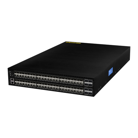
8. UART RJ-45 Serial Console Port 9. 10/100/1000Mb/s RJ-45 Ethernet Management Port The following figure shows the port numbering for the SAN128B-7 Switch. Trunk groups are outlined in red. 2 IBM Storage Networking SAN128B-7: SAN128B-7 Installation, Service, and User Guide... -
Page 27: Nonport-Side View
Figure 2. Port Numbering for the SAN128B-7 Switch Nonport-side view The following illustration shows the nonport-side view of the SAN128B-7 FC switch. Figure 3. Nonport-side view with AC power supply and fan assembly units 1. Power Supply Units (PSU 1 and PSU 2 from right to left) 2. - Page 28 Ethernet or serial Fabric OS Administration Guide connection Fabric OS Command Reference Manual IBM IBM SANnav Ethernet or serial IBM SANnav documentation set connection IBM SANnav must be purchased separately. 4 IBM Storage Networking SAN128B-7: SAN128B-7 Installation, Service, and User Guide...
-
Page 29: Chapter 2. Preparing For The Installation
Figure 4. Nonport-Side View with AC Power Supply and Fan Assembly Units 1. Power Supplies 2. Fan Assemblies 3. Ground Cable Connector After you have grounded the chassis, ensure that the following requirements are met. © Copyright IBM Corp. 2022... -
Page 30: Quick Installation Checklist
Decide whether you want to install the unit on a flat surface or in a rack. For rack installation, obtain the appropriate rack mount kit. Refer to Chapter 3, “Mounting the switch,” on page 10. 6 IBM Storage Networking SAN128B-7: SAN128B-7 Installation, Service, and User Guide... -
Page 31: Installation And Basic System Configuration
Table 4. Installation prerequisites (continued) Task Task details or additional information Complet Review and verify installation Verify that the following requirements are met. Refer to “Facility requirements. requirements” on page 5. • Power requirements • Environmental requirements • Clearance for standalone or rack installation Gather network configuration •... - Page 32 Optional: Power off the devices. Enter the shutdown command and wait for the device to power down, and then unplug the power cords. Refer to “Powering down the device” on page 40 for more information. 8 IBM Storage Networking SAN128B-7: SAN128B-7 Installation, Service, and User Guide...
-
Page 33: Shipping Carton Contents
When unpacking the switch, verify that the contents of the shipping carton is complete. Save the shipping carton and packaging in the event you need to return the shipment. • The SAN128B-7 switch • An accessory kit containing the following items: –... -
Page 34: Chapter 3. Mounting The Switch
1. Unpack the device and verify the items listed under “ Shipping carton contents” on page 9 are present and undamaged. 2. Apply the adhesive rubber feet to the underside of the device. The rubber feet help prevent the device from sliding off the supporting surface. 10 IBM Storage Networking SAN128B-7: SAN128B-7 Installation, Service, and User Guide... -
Page 35: Installing The Universal Four-Post Rack Kit
a) Clean the indentations at each corner of the bottom of the device to ensure that they are free of dust or other debris that might lessen the adhesion of the feet. b) With the adhesive side against the chassis, place one rubber foot in each indentation and press into place. -
Page 36: Parts List
7. Screw, 8-32 x 5/16-in., flathead Phillips (16) 8. Screw, 6-32 x 1/4-in., panhead Phillips (8) 9. Screw, 10-32 x 5/8-in., panhead Phillips (8) 10. Retainer nut, 10-32 (8) 12 IBM Storage Networking SAN128B-7: SAN128B-7 Installation, Service, and User Guide... -
Page 37: Flush-Front Mounting
Ensure that the items listed and illustrated are included in the kit. Note that not all parts may be used with certain installations depending on the device type. CAUTION: CAUTION: Use the screws specified in the procedure. Using longer screws can damage the device. - Page 38 4. Repeat step 2 and step 3 to attach the left bracket extension to the left side of the device. 5. Tighten all the 8-32 x 5/16-in. screws to a torque of 15 in-lb (17 cm-kg). 14 IBM Storage Networking SAN128B-7: SAN128B-7 Installation, Service, and User Guide...
-
Page 39: Attaching The Bracket Extensions To The Device
Figure 7. Attaching the bracket extensions to the device Bracket extension Screws, 8-32 x 5/16-in., flathead Phillips Installing the device in the rack Complete the following steps to install the device in the rack. 1. Position the device in the rack, as shown in Figure 8 on page 16, providing temporary support under the device until the rail kit is secured to the rack. -
Page 40: Positioning The Device In The Rack
4. Repeat step 2 and 3 to attach the left rear bracket to the left bracket extension. 5. Adjust the brackets to the rack depth and tighten all the 6-32 x 1/4-in. screws to a torque of 9 in-lb (10 cm-kg). 16 IBM Storage Networking SAN128B-7: SAN128B-7 Installation, Service, and User Guide... -
Page 41: Attaching The Rear Brackets To The Extensions
Figure 9. Attaching the rear brackets to the extensions 1. Rear brackets 2. Screws, 6-32 x 1/4-in., panhead Phillips Attaching the rear brackets to the rack posts Complete the following steps to attach the rear brackets to the rack posts. 1. -
Page 42: Flush-Rear (Recessed) Mounting
Attaching the front brackets to the rear of the device Note: In this installation, the brackets are named as listed in the parts list even though the installation of the brackets is reversed from the flush-front installation. 18 IBM Storage Networking SAN128B-7: SAN128B-7 Installation, Service, and User Guide... -
Page 43: Attaching The Front Brackets To The Rear Of The Device
4. Tighten all the 8-32 x 5/16-in. screws to a torque of 15 in-lb (17 cm-kg). Figure 11. Attaching the front brackets to the rear of the device 1. The SAN128B-7 device 2. Front brackets 3. Screws, 8-32 x 5/16-in., flathead Phillips Attaching the bracket extensions to the front of the device Complete the following steps to attach the bracket extensions to the front of the device. -
Page 44: Attaching The Bracket Extensions To The Device
3. Attach the left front bracket to the left rear rack post using two 10-32 x 5/8-in. panhead screws and two retainer nuts. Use the upper and lower holes in the bracket. 4. Tighten all the 10-32 x 5/8-in. screws to a torque of 25 in-lb (29 cm-kg). 20 IBM Storage Networking SAN128B-7: SAN128B-7 Installation, Service, and User Guide... -
Page 45: Positioning The Device In The Rack
Figure 13. Positioning the device in the rack Screws, 10-32 x 5/8-in., panhead Phillips Retainer nuts, 10-32 Attaching the rear brackets to the extensions at the front of the device Complete the following steps to attach the rear brackets to the extensions. There are short and long front brackets that you can use for this step. - Page 46 Figure 14. Attaching the rear brackets to the extensions at the front of the device 1. Rear brackets, short 2. Screws, 6-32 x 1/4-in., panhead Phillips 22 IBM Storage Networking SAN128B-7: SAN128B-7 Installation, Service, and User Guide...
- Page 47 Figure 15. Attaching the short or long rear brackets to the extensions 1. Rear bracket, short or long 2. Screws, 6-32 x 1/4-in., panhead Phillips Attaching the rear brackets to the front rack posts Complete the following steps to attach the rear brackets to the front rack posts. 1.
-
Page 48: Installing The Universal Two-Post Rack Kit
Allow 15 to 30 minutes to complete the installation. The following items are required to install the device using the Universal Two-Post Rack Kit: • #2 Phillips torque screwdriver 24 IBM Storage Networking SAN128B-7: SAN128B-7 Installation, Service, and User Guide... -
Page 49: Parts List
• 1/4-inch slotted-blade torque screwdriver Parts list The following parts are provided with the Universal Two-Post Rack Kit Installation. Figure 17. Rack kit parts 1. Front brackets (2) 2. Rear brackets, 5-6 inch post (2) 3. Rear brackets, 3-5 inch post (2) 4. - Page 50 2. Front brackets, right and left 3. Screws, 8-32 x 5/16-in., flathead Phillips Attaching the front brackets to the rack Complete the following steps to install the device in the rack. 26 IBM Storage Networking SAN128B-7: SAN128B-7 Installation, Service, and User Guide...
-
Page 51: Attaching Front Brackets To A Rack
1. Position the device in the rack, as shown in (Figure 19 on page 27), providing temporary support under the device until the rack kit is fully secured to the rack. 2. Attach the right front bracket to the right rack upright using two 10-32 x 5/8-in. panhead screws and two retainer nuts. -
Page 52: Attaching The Rear Brackets To A Rack
Again, use the upper and lower slots in the bracket. 3. Tighten all the 8-32 x 5/16-in. screws to a torque of 15 in-lb (17 cm-kg). 28 IBM Storage Networking SAN128B-7: SAN128B-7 Installation, Service, and User Guide... -
Page 53: Mid-Mounting
Figure 21. Attaching the rear brackets to the device 1. Screws, 8-32 x 5/16-in., panhead Phillips Mid-mounting Observe the following notes when using this procedure: • The device must be turned off and disconnected from the fabric during this procedure. •... -
Page 54: Attaching The Front Brackets
3. Attach the left front bracket to the left rack upright using two 10-32 x 5/8-in. screws and two retainer nuts. Use the upper and lower holes in the bracket. 4. Tighten all the 10-32 x 5/8-in. screws to a torque of 25 in-lb (29 cm-kg). 30 IBM Storage Networking SAN128B-7: SAN128B-7 Installation, Service, and User Guide... -
Page 55: Attaching Front Brackets To A Rack
Figure 23. Attaching front brackets to a rack 1. Screws, 10-32 x 5/8-in., panhead Phillips 2. Retainer nuts, 10-32 Attaching the rear brackets to the rack Complete the following steps to attach the rear brackets to the rack. 1. Select the proper length bracket for your post width. If your posts are three to five inches wide, use the brackets marked 3-5 INCH. -
Page 56: Attaching The Rear Brackets To A Rack
Again, use the upper and lower slots in the bracket. 3. Tighten all the 8-32 x 5/16-in. screws to a torque of 15 in-lb (17 cm-kg). 32 IBM Storage Networking SAN128B-7: SAN128B-7 Installation, Service, and User Guide... -
Page 57: Attaching The Rear Brackets To The Device
Figure 25. Attaching the rear brackets to the device 1. Screws, 8-32 x 5/16-in., panhead Phillips Chapter 3. Mounting the switch 33... -
Page 58: Chapter 4. Initial Setup And Verification
Chapter 4. Initial Setup and Verification Once you have set up the SAN128B-7 in a rack or as a standalone switch, it is time to attach power and set up a basic configuration. If you are going to use the SAN128B-7 in a single-switch setup, you can use EZSwitchSetup to complete the basic configuration. -
Page 59: Configuring The Ip Address
1. Connect the serial cable to the serial port on the device and to an RS-232 serial port on the workstation. If the serial port on the workstation is RJ-45 instead of RS-232, remove the adapter on the end of the serial cable and insert the exposed RJ-45 connector into the RJ-45 serial port on the workstation. -
Page 60: Using Dhcp To Set The Ip Address
• yy: Specifies the year, valid values are 00 to 37 and 70 to 99. Year values from 70 to 99 are interpreted as 1970 to 1999; year values from 00 to 37 are interpreted as 2000 to 2037. device:admin> date Thu Dec 22 14:05:10 UTC 2016 36 IBM Storage Networking SAN128B-7: SAN128B-7 Installation, Service, and User Guide... -
Page 61: Setting The Time Zone
device:admin> date "1222150617" Thu Dec 22 15:06:00 UTC 2017 Setting the time zone The default time zone is Coordinated Universal Time (UTC). The time zone must be set only once because the value is stored in nonvolatile memory. Use the following procedure to set the time zone. 1. -
Page 62: Customizing The Chassis Name And Switch Name
Enter y after the "Fabric param" prompt. Fabric param (yes, y, no, n): [no] y d) Enter a unique domain ID (such as the domain ID used by the previous switch, if still available). 38 IBM Storage Networking SAN128B-7: SAN128B-7 Installation, Service, and User Guide... -
Page 63: Verifying Correct Operation
Domain: (1..239) [1] 3 e) Complete the remaining prompts or press Ctrl+D to accept the remaining settings without completing all the prompts. f) Re-enable the switch by entering the switchEnable command. Verifying correct operation Perform the following steps to verify correct operation of the device. 1. -
Page 64: Backing Up The Configuration
2. Unplug the power cables from the power source before servicing the device or FRUs. All devices are returned to their initial state the next time the switch is powered on. 40 IBM Storage Networking SAN128B-7: SAN128B-7 Installation, Service, and User Guide... -
Page 65: Chapter 5. Installing Transceivers And Cables
• Required number of compatible power cables • Required number of supported transceivers DANGER: Use only optical transceivers that are qualified by IBM and comply with the FDA Class 1 radiation performance requirements defined in 21 CFR Subchapter I, and with IEC 60825 and EN60825. -
Page 66: Managing Cables
• Use hook and loop style straps to secure and organize fiber-optic cables. Installing an SFP+ transceiver The device supports only IBM-qualified transceivers. If you use an unqualified transceiver, the switchshow command output shows the port in a Mod_Inv state. The issue is also logged in the system error log. - Page 67 Figure 27. Installing a SFP+ transceiver into an upper port 1. Pull Tab of Transceiver in Upper Row 2. Pull Tab of Transceiver in Lower Row 2. Position a cable so that the key (the ridge on one side of the cable connector) is aligned with the slot in the transceiver.
-
Page 68: Replacing An Sfp+ Transceiver
For the top row of ports, insert the transceiver so that the pull tab is on the bottom. For the bottom row of ports, insert the transceiver so that the pull tab is on the top. 44 IBM Storage Networking SAN128B-7: SAN128B-7 Installation, Service, and User Guide... - Page 69 Figure 29. Installing SFP-DD transceivers 1. SFP-DD transceiver 2. Pull Tab of transceiver in lower row 3. Dust caps 4. Pull Tab of transceiver in upper row 2. Remove the first dust cap from the transceiver. Leave the second dust cap in place. 3.
-
Page 70: Replacing A Sfp-Dd Transceiver
Note: Grasp the tab near the body of the transceiver to reduce the chances of bending the pull tab. Avoid touching the transceiver because it may be hot. 3. To insert the replacement transceiver, refer “Installing an SFP-DD transceiver” on page 44 46 IBM Storage Networking SAN128B-7: SAN128B-7 Installation, Service, and User Guide... -
Page 71: Verifying The Operation Of New Transceivers
Verifying the operation of new transceivers Use the following commands to verify if the transceivers are working correctly. • errDump • fabricShow • sfpShow • switchShow Chapter 5. Installing Transceivers and Cables 47... -
Page 72: Chapter 6. Monitoring The Device
7. DD (Upper) Ports 96 and 97 Status LED 8. DD (Upper) Ports 96 and 97 9. DD (Lower) Ports 108 and 109 10. DD (Lower) Ports 108 and 109 Status LED 48 IBM Storage Networking SAN128B-7: SAN128B-7 Installation, Service, and User Guide... -
Page 73: System Power Led
System power LED Refer to the following table to interpret the system power status LED. Table 8. System power LED patterns during normal operation LED color Status of hardware Recommended action No light System is off or there is an Verify that system is powered on, internal power supply failure. -
Page 74: Fc Port Status Led
SFP-DD. When it blinks white twice, it shows the status of the second port of the SFP-DD. Refer to the following table to interpret the SFP-DD port status LEDs 50 IBM Storage Networking SAN128B-7: SAN128B-7 Installation, Service, and User Guide... -
Page 75: Nonport-Side Led Locations
Table 11. SFP-DD port status LED patterns during normal operation LED color Status of hardware Recommended action No light Port has no incoming power, or Verify that the power LED is on, there is no light or signal carrier and check the transceiver and detected. -
Page 76: Power Supply Leds
AC power source. Steady green No action required. AC input voltage is within operational range. 52 IBM Storage Networking SAN128B-7: SAN128B-7 Installation, Service, and User Guide... -
Page 77: Fan Assembly Status Led
• One or more of the fans in the fan assembly has failed. • Replace the faulty fan assembly. Note: The SAN128B-7 device requires minimum of two fan assemblies to be functional. Up to one fan assembly failure is supported. Interpreting the POST results Each time the switch is powered on, rebooted, or reset, the switch performs a power-on self-test (POST). -
Page 78: Interpreting The Boot Results
Note: Diagnostic tests may temporarily lock the transmit and receive speed of the links during diagnostic testing. Brocade recommends that you power-cycle the device after completing offline diagnostics tests. 54 IBM Storage Networking SAN128B-7: SAN128B-7 Installation, Service, and User Guide... -
Page 79: Chapter 7. Power Supply Assemblies
Chapter 7. Power Supply Assemblies The power supply assembly units in the SAN128B-7 chassis can be removed and replaced without special tools. The device can continue operating during the replacement. The device supports the following types of power supplies. • AC power supply with nonport-side air exhaust. This unit moves the air from the port-side to the nonport-side of the device. -
Page 80: Identifying The Airflow Direction
– Part numbers ending with -R • Exhaust power supply and fan assembly with a green "E" label: Pulls air from the port side of the switch and exhausts it out the nonport-side. 56 IBM Storage Networking SAN128B-7: SAN128B-7 Installation, Service, and User Guide... -
Page 81: Power Supply Assembly Unit Fault Indicators
– Nonport-side air exhaust – Port-side air intake – Front-to-back (port-side to nonport-side) airflow – Part numbers ending with -F Power supply assembly unit fault indicators Use one of the following methods to determine the status of the power supply assemblies: •... -
Page 82: Time And Items Required
1. To leave the device in service while removing a power supply assembly, verify that the other power supply assembly (the one not being replaced) has been powered on for at least four seconds and has a steady green LED. 58 IBM Storage Networking SAN128B-7: SAN128B-7 Installation, Service, and User Guide... -
Page 83: Inserting A New Power Supply Assembly
Figure 36. Removing a power supply assembly 1. Power Supply Assembly Unit 2. Power Supply Assembly Handle 2. Unplug the power cord from the power supply that is being replaced. 3. Push the lever on the lower right corner of the power supply unit towards the IEC socket. 4. -
Page 84: Verifying The Operation Of The Power Supply And Fan Assemblies
You can use the following commands to verify that the power supply and fan assemblies are operational: • errDump • fanShow • psShow • sensorShow • switchShow • tempShow Refer to the Fabric OS Command Reference for output examples and descriptions. 60 IBM Storage Networking SAN128B-7: SAN128B-7 Installation, Service, and User Guide... -
Page 85: Chapter 8. Fan Assemblies
Chapter 8. Fan Assemblies The fan assembly units in the SAN128B-7 chassis can be removed and replaced without special tools. The device can continue operating during the replacement. The device supports the following types of fan assemblies. • Fan assembly with nonport-side air exhaust. This unit moves the air from the port-side to the nonport- side of the device. -
Page 86: Precautions Specific To The Fan Assemblies
– Part numbers ending with -R • Exhaust power supply and fan assembly with a green "E" label: Pulls air from the port side of the switch and exhausts it out the nonport-side. 62 IBM Storage Networking SAN128B-7: SAN128B-7 Installation, Service, and User Guide... -
Page 87: Fan Assembly Unit Fault Indicators
– Nonport-side air exhaust – Port-side air intake – Front-to-back (port-side to nonport-side) airflow – Part numbers ending with -F Fan assembly unit fault indicators Use one of the following methods to determine the status of the fan assemblies: • Check the fan assembly status LED. Refer “Fan assembly status LED” on page 53 to interpret the meaning of LED operation. -
Page 88: Recording Fan Assembly Critical Information
The new fan assembly must have the same part number and airflow label (or lack thereof) as the fan assembly already installed. Complete the following steps to insert a new fan assembly into the chassis. 64 IBM Storage Networking SAN128B-7: SAN128B-7 Installation, Service, and User Guide... -
Page 89: Verifying The Operation Of The Power Supply And Fan Assemblies
1. To leave the device in service while installing a fan assembly, verify that the other fan assemblies (the ones already installed) have been powered on for at least four seconds and has a steady green LED. 2. Using a Phillips screwdriver, unscrew the captive screw of the filler panel that is located in the empty fan assembly slot. -
Page 90: Chapter 9. Chassis Replacement
Chapter 9. Chassis replacement The SAN128B-7 chassis is highly reliable and unlikely to fail. However, the chassis is available as a FRU and can be replaced using the following basic tasks. Since chassis replacement is a collaborative process between customers and SSRs please review the information provided in “Customer replacement responsibilities”... -
Page 91: Chassis Replacement Overview
Chassis replacement overview Use the following information to help prepare for a chassis replacement. Do not remove components without following procedures in this section exactly as you will need to save critical device and SAN information for these components before disconnecting the chassis from the network, fabric, and power to begin removal procedures. - Page 92 Output from license --show command License keys and other licensing data for licensed products enabled on device. Output from supportshow command Location of "spptshow.txt" file 68 IBM Storage Networking SAN128B-7: SAN128B-7 Installation, Service, and User Guide...
- Page 93 Table 14. Critical information checklist (continued) Checked? Data Notes Notes regarding supportshow output Information about the new chassis New factory serial number New serial number (if available) 2. Open a telnet session and log into the device as admin. The default password is password. Enable the logging function on your telnet or serial console connection.
- Page 94 10. Record the cable connections between the chassis and the target device and ports. 11. Run supportSave on the active CP blade. The information recorded can be very important in case you have difficulties during the replacement process. 70 IBM Storage Networking SAN128B-7: SAN128B-7 Installation, Service, and User Guide...
-
Page 95: Reconnecting System To The Network And Fabric
Powering down the switch If the switch is functioning at all, it must be disconnected from the network and fabric. To disconnect the switch from the network and fabric shut down the system by entering the sysShutdown command. Reconnecting system to the network and fabric Complete the following steps to reconnect the device to the network and fabric. -
Page 96: Verifying Correct Operation Of System
This switchShow command displays the device and port status information. switch0:admin> switchshow switchName: switchType: 165.0 switchState: Online switchMode: Native switchRole: Principal switchDomain: switchId: fffc82 switchWwn: 10:00:00:05:31:03:2c:00 zoning: ON (ZONE_CONFIG_NAME) 72 IBM Storage Networking SAN128B-7: SAN128B-7 Installation, Service, and User Guide... -
Page 97: Verifying Correct Configuration Of The Fabric
switchBeacon: FC Router: HIF Mode: Allow XISL Use: OFF LS Attributes: [FID: 128, Base Switch: No, Default Switch: Yes, Address Mode 0] Index Slot Port Address Media Speed State Proto ======================================================= 014000 Online F-Port 10:00:00:05:1e:f8:a0:b4 014100 Online F-Port 10:00:00:05:33:26:0e:65 014200 Online F-Port 10:00:00:05:33:48:5e:f5... -
Page 98: Ibm Service Replacement Responsibilities
• If other issues exist, contact your support provider. IBM service replacement responsibilities IBM System Services Representatives (SSR) are responsible for the physical replacement and labeling of the chassis. The SSR performs the following tasks during the replacement: 1. “Disconnecting the cables” on page 74 2. -
Page 99: Appendix A. Product Specifications
Appendix A. Product specifications This topic highlights the features and specifications for the SAN128B-7 switch. System specifications System component Description Enclosure 2U, power from back • Front-to-back airflow/nonport-side exhaust • Back-to-front airflow/nonport-side intake Power inlet Power supplies Dual, hot-swappable redundant power supplies with integral cooling fans and status LEDs. - Page 100 One bicolor fan assembly status LED on each fan assembly on the nonport-side of the switch. Other System component Description Serial cable RJ-45 console cable RJ-45 to DB9 adapter RJ-45 to DB9 for console cable 76 IBM Storage Networking SAN128B-7: SAN128B-7 Installation, Service, and User Guide...
- Page 101 Empty weight refers to the device with two power supply and fan assemblies installed but no SFP+ or SFP-DD transceivers. Model Height Width Depth Weight (empty) Weight (fully loaded) SAN128B-7 8.67 cm 44.00 cm 60.96 cm 18.92 kg 21.48 kg switch 3.41 inches 17.32 inches 24.00 inches...
- Page 102 190m (623 ft) (OM4) 62.5 21m (68 ft) 10 km (6.2 miles) 82m (269 ft) (OM2) 300m (984 ft) (OM3) 550m (1804 ft) (OM4) 62.5 33m (108 ft) 10 km (6.2 miles) 78 IBM Storage Networking SAN128B-7: SAN128B-7 Installation, Service, and User Guide...
- Page 103 Description Not supported Not supported Transmit data (output from SAN128B-7) Logic ground Logic ground Receive data (input into SAN128B-7) Not supported Not supported Note: These specifications are for the serial connector on IBM platforms only. Appendix A. Product specifications 79...
- Page 104 Serial port specifications (protocol) Parameter Value Baud 9600 (fixed speed) Data bits Parity None Flow control None Stop bits 80 IBM Storage Networking SAN128B-7: SAN128B-7 Installation, Service, and User Guide...
-
Page 105: Appendix B. Cable Routing Table
Appendix B. Cable routing table If the information is not already available, have the customer use Table 15 on page 81 to record cable routing information. Table 15. Cable routing table for SAN128B-7 Slot/Port of the Port Cable labels Connected device... - Page 106 Table 15. Cable routing table for SAN128B-7 (continued) Slot/Port of the Port Cable labels Connected device device 82 IBM Storage Networking SAN128B-7: SAN128B-7 Installation, Service, and User Guide...
-
Page 107: Notices
Consult your local IBM representative for information on the products and services currently available in your area. Any reference to an IBM product, program, or service is not intended to state or imply that only that IBM product, program, or service may be used. Any functionally equivalent product, program, or service that does not infringe on any IBM intellectual property right may be used instead. -
Page 108: Trademarks
International Business Machines Corp., registered in many jurisdictions worldwide. Other product and service names might be trademarks of IBM or other companies. A current list of IBM trademarks is available on the web at Copyright and trademark information athttp://www.ibm.com/legal/copytrade.shtml Adobe, the Adobe logo, PostScript, and the PostScript logo are either registered trademarks or trademarks of Adobe Systems Incorporated in the United States, and/or other countries. -
Page 109: Australia And New Zealand Class A Statement
2014/30/EU on the approximation of the laws of the Member States relating to electromagnetic compatibility. IBM cannot accept responsibility for any failure to satisfy the protection requirements resulting from a non-recommended modification of the product, including the fitting of non-IBM option cards. -
Page 110: People's Republic Of China Class A Statement
Handbüchern beschrieben zu installieren und zu betreiben. Des Weiteren dürfen auch nur von der IBM empfohlene Kabel angeschlossen werden. IBM übernimmt keine Verantwortung für die Einhaltung der Schutzanforderungen, wenn das Produkt ohne Zustimmung von IBM verändert bzw. wenn Erweiterungskomponenten von Fremdherstellern ohne Empfehlung von IBM gesteckt/eingebaut werden. -
Page 111: Taiwan Class A Statement
Taiwan Class A Statement Taiwan Contact Information This topic contains the product service contact information for Taiwan. IBM Taiwan Product Service Contact Information: IBM Taiwan Corporation 3F, No 7, Song Ren Rd., Taipei Taiwan Tel: 0800-016-888 Japan Voluntary Control Council for Interference Class A Statement This explains the Japan Voluntary Control Council for Interference (VCCI) statement. -
Page 112: Korean Communications Commission Class A Statement
Korean Communications Commission Class A Statement This explains the Korean Communications Commission (KCC) statement. Russia Electromagnetic Interference Class A Statement This statement explains the Russia Electromagnetic Interference (EMI) statement. 88 IBM Storage Networking SAN128B-7: SAN128B-7 Installation, Service, and User Guide... -
Page 113: Index
Index SAN128B-7 library xxii accessibility features ix cable connections 81 cable routing 81 caution notices definition xi examples xi chassis replacing 66 danger notices definitions xiii examples xiii director of licensing, address 83 intellectual property 83 license, for patents 83... - Page 114 IBM® Part Number: 01JC301 P32601...
Need help?
Do you have a question about the SAN128B-7 and is the answer not in the manual?
Questions and answers