
Related Manuals for Halton Capture Ray KVE-UV


Summary of Contents for Halton Capture Ray KVE-UV
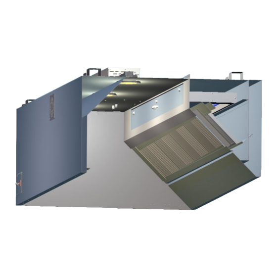
- Page 1 Operators Manual for Capture Ray (UV) ® Manual provides Operation, Maintenance and Service Instructions Capture Ray Hoods with UV Technology ® KVE-UV, KVC-UV, KVL-UV, KVW-UV Form#: OM010_CAPTURE RAY (UV) Date: July 2017 - Rev4...
-
Page 2: General Description
RECOMMENDATION Upon receipt of the Halton hood (s), inspect unit (s) immediately for any shipping damage and notify carrier immediately if damage is found. Halton will not accept responsibility for any shipping damage. All systems are thoroughly inspected before leaving our factories; however Halton will assist in filing a claim if needed. -
Page 3: Installation Instructions
The owner and/or operator should be instructed in the proper operation, care and maintenance of the system. If questions or complications should arise during the installation of the Halton hood (s) that cannot be solved using the instructions provided please contact the Halton office at 1-800-442-5866, or (1-800-4-HALTON). - Page 4 48” long in fluorescent fixtures. **Note: Halton does not provide bulbs for incandescent or fluorescent lights. 9. If Closure Panels are supplied by Halton see pg. 9 for details on the installation. 10. For multiple hoods end to end, or back to back see pg. 8 for Installation of Splice Strips and U-Channels.
-
Page 5: Backsplash Installation
BACKSPLASH INSTALLATION Capture Ray UV Operation & Maintenance Manual ®... - Page 6 HOOD INSTALLATION DETAILS Capture Ray ® UV Operation & Maintenance Manual...
- Page 7 EXHAUST DUCT CONNECTION DETAILS Capture Ray UV Operation & Maintenance Manual ®...
- Page 8 SPLICE STRIP/U-CHANNEL ASSEMBLIES Capture Ray ® UV Operation & Maintenance Manual...
- Page 9 CLOSURE PANEL ASSEMBLY - SINGLE HOOD Capture Ray UV Operation & Maintenance Manual ®...
- Page 10 CLOSURE PANEL ASSEMBLY - END TO END HOODS Capture Ray ® UV Operation & Maintenance Manual...
- Page 11 CLOSURE PANEL ASSEMBLY - BACK TO BACK HOODS CLOSURE PANEL ASSEMBLY - END TO END BACK TO BACK HOODS Capture Ray UV Operation & Maintenance Manual ®...
- Page 12 On the Capture Jet line of hoods, ® Halton supplies T.A.B. (Testing And Balancing) ports for measuring the negative static pressure drop through the filters and also the positive Capture Jet plenum pressure. These ports are located on the ®...
- Page 13 using the negative connection on the manometer, leaving the positive port of the manometer open to atmosphere. The Capture Jet static pressure is measured using the positive connection on ® the manometer, leaving the negative port of the manometer open to atmosphere. Adjustment to the static pressure of the exhaust plenum is made by adjusting the speed of the exhaust fan.
- Page 14 Halton UV system grease filters must be removed and replaced in a certain order. Please see detailed instructions on pg. 16 that describe the removal and replacement process.
- Page 15 continues to operate normally. If the output has dropped below 80% of new, and the lamps have more than 500 hours since they were last cleaned a “Clean UV” alarm appears on the control panel. This means it is time to clean the lamps in the UV cassettes found in the grease plenum of the hood. If the output has dropped below 80% of new and the lamps have less than 500 hours since they were last cleaned a “Replace UV”...
- Page 16 Halton highly recommends that the facility enter into a formal annual maintenance contract with the local Authorized Service Agent. Contact the factory directly if you would like the name and phone number of the local ASA. Clean the hood canopy inside and out as needed with mild soap and water. Never use harsh or abrasive cleaners on Stainless Steel or Painted surfaces, making sure to wipe clean all interior and exterior surfaces of the hood including the light fixtures.
- Page 17 KSA, GPS & UV BULBS & CASSETTE CLEANING INSTRUCTIONS: As previously stated, Halton highly recommends that the facility enter into a formal annual maintenance contract with the local Authorized Service Agent. Contact the factory directly if you would like the name and phone number of the local ASA.
- Page 18 Once the supply wiring has been disconnected the cassette should be removed by sliding it forward and out of the cassette tray. Handle the UV cassette only by the steel framework. Never pull the cassette or carry the cassette by the glass bulbs. Be sure when placing the cassette on any surface that there is no object that will strike or put pressure on the glass bulbs.
- Page 19 INSTRUCTION FOR RE-LAMPING 1. With the cassette removed from the hood, remove the screws from the end caps #3. 2. Unplug the lamps from lamp sockets #4. 3. Carefully slide each bulb through the lamp grommets. 4. Remove the lamp grommets #2 and replace with new grommets. 5.
- Page 20 BLACK SUPPLY JUMPER NUT OR SPADE CAPACITOR BLACK CAPTURE JET BLOWER MOTOR SPEED 120/1/60 CONTROLLER .72 AMPS BY HALTON LIGHT SWITCH FAN SWITCH BY ELECTRICIAN 120/1/60 120V, SWITCHED FUSE GROUND 120V R1-1 ADDITIONAL RELAY NOTE THE USE OF R2 IS...
- Page 21 UV CONTROL PANEL • 120V, 60Hz supply voltage • All field wiring 24VAC • Controls UV functions, exhaust fan and make up fan • One control panel per exhaust fan required regardless of number of UV hoods • Either local or remote ON/OFF operation • Interlock with fire system • Touch screen user friendly interface • Total number of UV hours operation monitored as well as hours since last UV tubes cleaning...
-
Page 22: System Off
UV CONTROL PANEL - SEqUENCE OF OPERATION System ON • UV On • Exhaust fan On • Makeup fan On System OFF • UV Off • Exhaust fan runs for 30 sec to exhaust ozone from the system and turns Off • Makeup fan On Fire • Exhaust fan will continue to run or it will start (even if system is off). - Page 23 UV Info Screen Press the “UV Info” button on Main screen to navigate to UV Info screen to read the total number of hours of UV operation and the number of hours since last cleaning. It also allows resetting those statistics. The number of hours since last cleaning has to be reset after each UV lamp cleaning.
- Page 24 This screen will pop up with your Name and Password entered. Press the “login” button to be logged in. New screen shows that you are logged in as User: 0000 Exit the security screen by pressing the Exit button. You will be taken back to the “UV Info” screen already logged in as User 0000 To reset any of those statistics press corresponding “Reset”...
- Page 25 Alarm Info Screen If during normal operation any alarm is activated, the screen automatically switches to “Alarm info” screen and the back light turns red. Active alarms is displayed as well as System status (fans) and UV status. If all alarms are cleared, the screen switches automatically to “Main” and back lights turns green. You can navigate manually from the “Alarm info”...
- Page 26 ALARMS “Low airflow” – Pressure switch from each hood is connected to terminals 1 and 15. Alarm is activated on switch closure. There is a 60 sec. delay to activate this alarm. It allows the pressure to built-up in a system after exhaust fan starts as well as to prevent false alarms on pressure fluctuation. UV in affected hood only is turned off.
- Page 27 Field Wiring to UV Control Panel The panel requires 120V/60Hz, 5Amps supply. All field wiring is low voltage, 24VAC. EFO Jumper * * Install “EFO Jumper” if Exhaust Fan is required to be ON in fire mode. Capture Ray UV Operation & Maintenance Manual ®...
- Page 28 WARRANTY ACTIVATION FORM This form must be completed and returned to Halton in order for your warranty to be valid. Job & Location Information: Job Name: Street Name: Zip Code: City: State: Equipment Start-Up Date: Product Serial Numbers: Contact Information:...
- Page 29 All products sold but not manufactured by Manufacturer will be warranted for a period of twelve (12) months from date of shipment. (Halton’s Warranty Card must be completely filled out and returned to Halton within 3 weeks after the equipment start-up date for your warranty to be valid *IMPORTANT NOTE: “IF”...
Need help?
Do you have a question about the Capture Ray KVE-UV and is the answer not in the manual?
Questions and answers