
Subscribe to Our Youtube Channel
Related Manuals for Halton Capture Jet KVESJ


Summary of Contents for Halton Capture Jet KVESJ
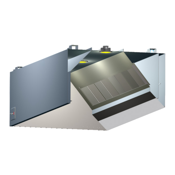
- Page 1 Operators Manual for Capture Jet ® Manual provides Operation, Maintenance and Service Instructions Capture Jet Hoods ® KVE (SJ-SK), KVC (SJ-SK), KVW (SJ-SK), KVL, KVM KVR, KVO AND KCH Form#: OM005_CAPTURE JET Date: May 2017 - Rev2...
-
Page 2: General Description
The owner and/or operator should be instructed in the proper operation, care and maintenance of the system. If questions or complications should arise during the installation of the Halton hood (s) that cannot be solved using the instructions provided please contact the Halton office at 1-800-442-5866, or (1-800-4-HALTON). -
Page 3: Installation Instructions
Please note only install 100 watt maximum light bulbs in incandescent light fixtures. Fluorescent bulbs should be type T8, 36” or 48” long in fluorescent fixtures. **Note: Halton does not provide bulbs for incandescent or fluorescent lights. -
Page 4: Operation Of System
The submittal drawings will detail the location of the speed controller(s). Information regarding the fan and speed controller (see pg. 12). 2. Halton Capture Jet Hoods are equipped with efficient model KSA grease filters. Each Halton Capture Jet hood ®... - Page 5 *( screw head will not interfere with hood) Screw backsplash to wall or attach with adhesive. Halton canopy hoods should be installed from 78” min.- 84” max. above the Flat Sheet Backsplash Assembly finished floor. Capture Jet Operation &...
- Page 6 Typical Hood Installation Details *Optional Unistrut / Turn Buckle Detail Hanger Bracket / Turn Buckle Detail - Welded to top of hood. 18 ga. material All Thread (By Others) Hang the hood using 1/2” threaded rods by attaching the rods to the hood through the hanger brackets (as shown) which are fastened to the top of the hood, using the turnbuckles will make final adjustments easier.
- Page 7 Recommended Exhaust Duct Installation Details Exhaust Duct Options Available Supply Exhaust Duct Duct per code Supply Duct Supply Duct may be attached to supply collar with sheet metal screws or pop rivets and sealed with duct tape. Screws or Rivets are not to interfere with the operation of the fire damper (if equipped).
- Page 8 Splice Strip / U-Channel Assemblies Hoods shown back to back Fig. 1 U-Channel Installation Notes: U-Channel: For hood models that are placed back to back (as shown in Fig. 1): Slide the U-Channel A up over the back of the hood systems, and secure with sheet metal screws.
- Page 9 Slide front panel “A” into place. Attach panels “B” to wall using appropriate hardware “D” . Be sure closure panels are vertical and aligned with hood end walls. *(Hardware not provided by Halton) Capture Jet Operation & Maintenance Manual ®...
- Page 10 BLACK SUPPLY JUMPER NUT OR SPADE CAPACITOR BLACK CAPTURE JET BLOWER MOTOR SPEED 120/1/60 CONTROLLER .72 AMPS BY HALTON LIGHT SWITCH FAN SWITCH BY ELECTRICIAN 120/1/60 120V, SWITCHED FUSE GROUND 120V R1-1 ADDITIONAL RELAY NOTE THE USE OF R2 IS...
- Page 11 Hood Wiring Details The Halton hood is equipped with a Timer Panel which fulfils the International Mechanical Code required interlock which will turn on the exhaust fan serving the hood if an appliance is turned on without also turning on the fan. This is accomplished with a temperature sensor in the hood that senses elevated temperature in the hood.
- Page 12 ® (Standard) (Optional) Typical Wiring of External KSA Filter Capture Jet ® T.A.B. Ports BY HALTON Speed Controller FIELD WIRING CAPACITOR Models KVE, KVC, KVR, KVW and KCH are equipped with an Integrated Capture Jet ® package, as shown above.
- Page 13 ® The Halton Capture Jet fan is factory set and should not need adjustment. If adjustment is necessary it may be adjusted for air flow output. Before any adjustment measure the static pressure produced by the Capture Jet fan at the Capture Jet plenum TAB (Testing And Balancing) port.
- Page 14 T.A.B.™ - Testing and Balancing Ports Closeup view of T.A.B. Port **** It is very important the cooking equipment is in operation to create a thermal plume, prior to the air balancer, to be able to use the T.A.B. ports. ****For accurate results, the balance contractor should receive a copy of the job specific hood plans with the de- sign T.A.B.
- Page 15 KSA Filter Removal with Model KFR S.S. Coupling S.S. Pipe 16 ga. S.S. Bracket To assemble the KFR filter remover: Screw together stainless steel pipe, coupling, and bracket and tighten all joints. (as shown in above picture) Filter Installation and Removal To remove filter: Insert bracket into the inside KSA filter slots, and lift upward until...
- Page 16 Model Typical Installation UL listed upblast fan for restaurant cooking appliances 40 “ min. 16 ga. duct work all welded per code **Incandescent or Standard top mounted Fluorescent lighting Capture Jet intake) available. ® KSA Filters Capture Jet Airflow 78”-84” A.F.F. Standard **(Verify with Authority in project location for...
- Page 17 Model Typical Installation 120” min. 40” min. Filtered MUA unit on the roof 16 ga. duct work all welded per code Stainless Steel KSA filters Make-up airflow Capture Jet ® 78” - 84” A.F.F. 78” Std. **(Verify with Authority in project location for min.
- Page 18 Model Typical Installation See page (22) for supply options UL listed upblast fan for restaurant cooking appliances 40” min. Integrated Capture Jet ® location 78” - 84” A.F.F. (78” Std.) **(Verify with Authority in project location for min. hanging height) Side view of typical install Exhaust Air Integrated...
- Page 19 Model Typical Installation Exhaust Air (W/ 1 Perf Plenum) Supply Air LED lighting Capture Jet ® Drop Ceiling T.A.B. Ports S.S. Perf (Low Velocity) KSA filters Capture Jet ® (W / 2 Perf Plenum) Exhaust Air Supply Air Supply Air LED lighting Capture Jet ®...
- Page 20 Model Typical Installation UL listed upblast fan for restaurant cooking appliances 40” min. 16 ga. duct work all welded per code Capture Jet ® Capture Jet ® **(Verify with Authority in project location for min. Stainless hanging height) Steel KSA filters 58”...
- Page 21 Model Typical Installation UL listed upblast fan for restaurant cooking appliances 40” min. 16 ga. duct work all welded per code Capture Jet ® Stainless Steel KSA filters Rear Seal Capture Jet Operation & Maintenance Manual ®...
- Page 22 Model Side Skirt Installation Panels “A” are placed at the outside ends of the hood at each end of the hood group. 2. Align the weld studs on the upper edges of the side skirts with the holes in the lower edge of hood ends and hang the panels on the ends of the hood group.
- Page 23 KVO & KVR Model Oval and Round Hood Systems 3D Plan view of round KVR 3D Plan view of oval KVR Model KVR Round and Oval hoods can be shipped in pieces for field assembly. If pieces are shipped loose, parts will be marked for easy assembly, and an Operation and Installation, and Maintenance manual will be provided.
- Page 24 Model Typical Installation Capture Jet ® Operation & Maintenance Manual...
- Page 25 WARRANTY ACTIVATION FORM This form must be completed and returned to Halton in order for your warranty to be valid. Job & Location Information: Job Name: Street Name: Zip Code: City: State: Equipment Start-Up Date: Product Serial Numbers: Contact Information:...
- Page 26 All products sold but not manufactured by Manufacturer will be warranted for a period of twelve (12) months from date of shipment. (Halton’s Warranty Card must be completely filled out and returned to Halton within 3 weeks after the equipment start-up date for your warranty to be valid *IMPORTANT NOTE: “IF”...
Need help?
Do you have a question about the Capture Jet KVESJ and is the answer not in the manual?
Questions and answers