
Subscribe to Our Youtube Channel
Related Manuals for Halton MM1 Series


Summary of Contents for Halton MM1 Series
- Page 1 Operators Manual for MM1 Series Hood Manual provides Operation, Maintenance and Service Instructions MM1 Series Hoods Model: MM1 Form#: OM032_MM1_Series_Hoods Date: 09-2018- Rev6...
-
Page 2: General Description
GENERAL DESCRIPTION Halton’s MM1 Series hood is designed to efficiently capture and remove the grease, smoke, and other effluents generated when cooking with pizza ovens. The hood is designed to mount close to the top of the pizza oven which provides an operational advantage of capturing the grease, smoke and other effluents directly above the pizza oven outlets. -
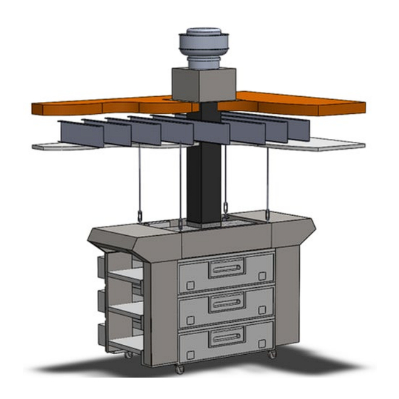
Page 3: System Capabilities
(single, double and triple stack) to reduce the required exhaust airflow. An optional eyebrow over the front loading window is available when desired or required by local codes. SYSTEM OVERVIEW MM1 Series Hood Installation, Operation & Maintenance Manual... -
Page 4: Parts Identification
PARTS IDENTIFICATION MM1 Series Hood Installation, Operation & Maintenance Manual... - Page 5 ITEMS SHIPPED INSIDE CONTROL PANEL MM1 Series Hood Installation, Operation & Maintenance Manual...
- Page 6 Do not lose these parts found inside the control panel; they are very important to the operation of the MM1 hood. The control panel will be replaced using all 8 screws after all field wiring is completed. MM1 Series Hood Installation, Operation & Maintenance Manual...
- Page 7 Molex connector is easily accessible for connection. See examples below. Installation of Current Switch on 360G MM1 Series Hood Installation, Operation & Maintenance Manual...
- Page 8 Installation of Current Switch on 570/670 Alternate Installation of Current Switch on 570/670, wires routed into electrical access panel MM1 Series Hood Installation, Operation & Maintenance Manual...
- Page 9 Note: On the 570/670 ovens if the wires are routed through the electrical access panel drilling the hole can be avoided. If wires are routed in this fashion ensure they are not pinched in any of the doors. See the alternate 570/670 examples below. MM1 Series Hood Installation, Operation & Maintenance Manual...
- Page 10 360G Harness Routing, 2 Deck Example 360G Harness Installation Example MM1 Series Hood Installation, Operation & Maintenance Manual...
- Page 11 670 Harness Routing, 3 Deck Example 670 Harness Installation Example MM1 Series Hood Installation, Operation & Maintenance Manual...
- Page 12 F . The 8 pin connector should be positioned near the control panel location with sufficient slack to allow for connection to the panel. Secure with fastener mount cable holders as necessary, see photo below. MM1 Series Hood Installation, Operation & Maintenance Manual...
- Page 13 H. Repeat the process for the remaining oven decks. I. When an extra connection is present, safely store in the lowest cabinet, see photo below. The harness is designed to accommodate a triple stack oven. MM1 Series Hood Installation, Operation & Maintenance Manual...
- Page 14 1 and 2. Please see details; item seven on page 30 and wiring diagram page 35. MM1 Series Hood Installation, Operation & Maintenance Manual...
- Page 15 Side Skirt Attachment Side Skirt Knobs Side Skirt Attachment Side Skirt Attachment MM1 Series Hood Installation, Operation & Maintenance Manual...
- Page 16 MM1 Series Hood Installation, Operation & Maintenance Manual...
- Page 17 11.5” X 11.5” to the exhaust fan. A transition from the 14” X 14” exhaust collar to 11.5” X 11.5” exhaust MM1 Series Hood Installation, Operation & Maintenance Manual...
- Page 18 Fire suppression systems may not be required in some jurisdictions. Skip this step if no fire suppression system for the ovens is in place. MM1 Series Hood Installation, Operation & Maintenance Manual...
- Page 19 Exhaust Fan Control photo below. Terminate the wire shield to a chassis ground at the control panel. Suggested field installed connection for the exhaust fan is 2 strand, 18 gauge minimum, shielded, plenum rated cable. Terminal Strip MM1 Series Hood Installation, Operation & Maintenance Manual...
- Page 20 RTC Solutions FSC Speed Controller MM1 Series Hood Installation, Operation & Maintenance Manual...
- Page 21 Greenheck Fan Controller Exhaust Fan Control MM1 Series Hood Installation, Operation & Maintenance Manual...
- Page 22 Wiring for S&P fan with PerfectSpeed Controller PerfectSpeed Controller on Fan PerfectSpeed Controller Wiring MM1 Series Hood Installation, Operation & Maintenance Manual...
- Page 23 10. Commission system (starting on page 29). Make sure grease filters and grease cups are installed in place before start-up. 11. Check airflow balance in store, and perform final inspection (page 31). MM1 Series Hood Installation, Operation & Maintenance Manual...
- Page 24 Fasten the conversion bracket together down the center of the bracket with the provided screws. Reinsert the crumb tray from the end of the conveyor into the new bracket. See illustrations below. MM1 Series Hood Installation, Operation & Maintenance Manual...
- Page 25 For Installation and Control Wiring questions: call EVS at 586-779-0996. Downloadable manuals may be found at www.evsvent.com MM1 Series Hood Installation, Operation & Maintenance Manual...
-
Page 26: Fire Suppression System
The illustrations below depict the typical layout for an MM1 hood fire system. The pre-pipe components supplied by Halton are shown in solid lines and the components supplied by others are shown in dashed lines. The complete fire system must satisfy the requirements of the National Fire Protection Association (NFPA), Underwriters Laboratories Standard 300 and all local codes and Authorities Having Jurisdiction. - Page 27 MM1 Typical Fire Suppression System Isometric View MM1 Series Hood Installation, Operation & Maintenance Manual...
- Page 28 MM1 Typical Fire Suppression System Schematic MM1 Series Hood Installation, Operation & Maintenance Manual...
- Page 29 3. Turn on the top oven deck and verify that the Exhaust Fan, the Make Up Air and the Top Deck (Oven 1 Status) lights are illuminated. See the status designations in photo below. MM1 Series Hood Installation, Operation & Maintenance Manual...
- Page 30 8. If ovens are a WOW series oven (Oven Models 770, 670, 640, 360G - ovens will say WOW! on the front as well as have sensors near the belts and a touch screen on the front) the RED jumper from terminals 3 to 4 should be removed. (page 34,35). MM1 Series Hood Installation, Operation & Maintenance Manual...
-
Page 31: Air Balance
• Exhaust Hood is Listed per UL710 • Exposed Surfaces are 430 Stainless Steel Optional Equipment • Side Skirts (Painted is Optional) • Front Eyebrow Section • Cool Front Modified End Panels MM1 Series Hood Installation, Operation & Maintenance Manual... -
Page 32: Parts List
14” x 14” to 11.5” x 11.5” transition 57443 9” Duct Collar Extension 14PSW9 (3AO) (Round Duct) 11461 Collar Connector 14PICRHC (3AO) (Round Duct) 11462 WIRING DIAGRAMS 0-10VDC Common SHIELD PRESSURE TRANSMITTER 0-0.5"WC -24DC +24DC MM1 Series Hood Installation, Operation & Maintenance Manual... - Page 33 Wiring Diagram Detail – Oven Wiring Harness, 8 Pin Connector MM1 Series Hood Installation, Operation & Maintenance Manual...
- Page 34 Wiring Diagram Detail – Field wiring close up Airflow Jumper Detail –Wiring close up MM1 Series Hood Installation, Operation & Maintenance Manual...
- Page 35 Wiring Diagram Detail – Jumper wiring close up MM1 Series Hood Installation, Operation & Maintenance Manual...
- Page 36 Jumper Positions on MC8 Controller MM1 Series Hood Installation, Operation & Maintenance Manual...
- Page 37 Appendix 2 Pre-Fab Duct Installation MM1 Series Hood Installation, Operation & Maintenance Manual...
-
Page 38: Warranty
WARRANTY Halton Company warrants all MM1 hoods for a period of 12 months from date of shipment to be without defects in workmanship and material. Omissions or defects will be re- placed or repaired at Halton’s option. Halton will not accept labor charges without prior approval.
Need help?
Do you have a question about the MM1 Series and is the answer not in the manual?
Questions and answers