Halton EcoloAir 3000CFM Operator's Manual
Hide thumbs
Also See for EcoloAir 3000CFM:
- Installation manual (11 pages) ,
- Operator's manual (30 pages) ,
- Installation manual (6 pages)
Table of Contents
Advertisement
Quick Links
Operators Manual
Operation, Maintenance and Service Instructions
UL 1978, "Standard for Grease Ducts" and/or
UL 710, "Exhaust Hoods for Commercial Cooking Equipment"
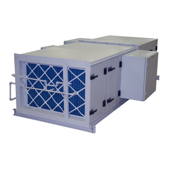
EcoloAir Unit
3000CFM, 4000CFM, 5000CFM, 6000CFM, 8000CFM,
10000CFM, 12000CFM, 15000CFM, 18000CFM,
20000CFM, 24000CFM, 28000CFM, 32000CFM,
36000CFM, 40000CFM
Advertisement
Table of Contents

Subscribe to Our Youtube Channel
Related Manuals for Halton EcoloAir 3000CFM


Summary of Contents for Halton EcoloAir 3000CFM
- Page 1 Operators Manual Operation, Maintenance and Service Instructions UL 1978, “Standard for Grease Ducts” and/or UL 710, “Exhaust Hoods for Commercial Cooking Equipment” EcoloAir Unit 3000CFM, 4000CFM, 5000CFM, 6000CFM, 8000CFM, 10000CFM, 12000CFM, 15000CFM, 18000CFM, 20000CFM, 24000CFM, 28000CFM, 32000CFM, 36000CFM, 40000CFM...
- Page 2 GENERAL The EcoloAir System should be installed, operated and maintained as illustrated in the Installation Instruction Manual, and the Operation and Maintenance Instruction. EcoloAir Operation, Maintenance & Service Manual...
- Page 3 MAJOR COMPONENTS FOR ECOLOAIR 1. EcoloAir Control Panel 3. Exhaust Fan Module 2. Filter Module 4. Odor Reducing Module EcoloAir Operation, Maintenance & Service Manual...
- Page 4 FILTER AND ODOR REDUCING MODULES The fi lter and odor reducing modules are made up of the following: 1. Pre Filter 40% Effi cient (ASHRAE) 2. Medium Filter 95% Effi cient (ASHRAE) 3. High Effi ciency Filter 95% Effi cient (ASHRAE) 4.
- Page 5 PRESSURE SWITCH AIR TUBE PARTS Mullion Pressure Switch Air Tube 16 Gauge Bottom Panel Pressure Switch Air Tube Connecting Nut Structural Base Elbow Fire Proof Door Gasket 16 Gauge Top Panel Filter By-Pass Gasket Elbow Lock Nut EcoloAir Operation, Maintenance & Service Manual...
-
Page 6: Filter Replacement
FILTER REPLACEMENT To replace fi lters, proceed as follows: 1. Shut off fan. 2. Loosen the access door latches and open door. 3. Check how fi lters are set in place to prevent air by-pass. 4. Remove fi lter clamp on absolute fi lters with hook handle provided in unit, located on inside of access door. - Page 7 J. Turn Number 4 Overall Pressure Switch clockwise until alarm sounds, Indicator Light illuminates and then Fan unit shuts down. Note setting on Pressure Switch. K. Reset overall Pressure Switch one full turn counter clockwise from Trigger Setting in Step J. L.
-
Page 8: Fire Damper
2. Remove defective fusible link and replace with new link, by holding up damper blades and wrapping link support across blades and secure at clip, on other side of frame. 3. Close the access door and lock all latches. 4. Start Fan. HALTON ECOLOAIR FILTER QUANTITY CHART PRE FILTER MEDIUM FILTER ABSOLUTE FILTER... -
Page 9: Odor Control
ODOR CONTROL To replace a 5 Gallon bottle of Ecolo Scentry Solution 1. Open enclosure cabinet door by unscrewing the two lock bolts. 2. Remove the cap from the empty bottle. 3. Pull the dip tube assembly out of the empty bottle. 4. -
Page 10: Fan Types
EXHAUST FAN MODULE Access Door Fan Pulley Side Panel Fan Belt Corner Panel Motor Disconnect Switch Motor Pulley Hanger or Lifting Brackets Electrical Box Terminal Strip Spring Isolators Pressure Switch (optional location) Floating Steel Base Firestat Motor Slide Base Air Tubes for Pressure Switch (optional location) Structural Base Pressure Switch Box Cover (optional location) Bottom Panel... -
Page 11: Bearing Replacement
It is unlikely the fan wheel will require replacement. However, if the wheel requires balancing, it can normally be done in the fi eld by a certifi ed fan technician. Should the fan wheel require replacement, the work should only be performed by a Halton certifi ed fan technician. BEARING REPLACEMENT 1. -
Page 12: Sheave Alignment
SHEAVE ALIGNMENT Align the drive by the four-point method with a piece of string or a straight edge. The two sheaves will be aligned when two points (near and far) on the face of each of the sheaves touch the straight edge of the string when the string is a straight line. -
Page 13: Belt Adjustment
BELT ADJUSTMENT Measure the belt span, (see image). Using a spring scale, apply a perpendicular force to any one of the belts at the mid point of the span. Measure the force required to defl ect any one of the belts 1/64” (.40mm) for every inch (25mm) of span length. - Page 14 ECOLOGY CONTROL PANEL OPTIONAL RECESSED TRIM ANGLE (SHIPPED LOOSE) 24V. RETURN 120V. SUPPLY OPTIONAL SYSTEM OK ALARM RECESSED TRIM ANGLE (SHIPPED LOOSE) OFF ON CYCL/OFF/CONT DOOR LATCH ALARM HORN ELECTRICAL COMPARTMENT HINGED DOOR 12" (305) CONTROL PANEL MODELS EPLV5 - 1 : w/WASH HOODS, w/ECOLO EPLV5 - 1A : w/ WASH HOODS EPLV5 - 3 : w/DRY HOODS, w/ECOLO EPLV5 - 3A : w/DRY HOOD...
-
Page 15: Troubleshooting Guide
TROUBLESHOOTING GUIDE PROBLEM PROBABLE CAUSE SOLUTION Unit not exhausting properly a) Belts slipping or broken. a) Tighten or replace belts. b) Fire damper shut. Check b) Replace fusible link or holding ecology unit and exhaust wire. Check cause. hood. c) Plugged fi lter. c) Replace fi... -
Page 16: Troubleshoting Guide
TROUBLESHOTING GUIDE PROBLEM PROBABLE CAUSE SOLUTION Filter alarms triggering a) Plugged fi lter. a) Check fi lter. Replace if required What setting did it alarm at? Adjust pressure switch if required. b) Broken pressure switch air b) Repair break. Check for cause tube. -
Page 17: Maintenance Instructions
START UP OPERATING INSTRUCTIONS IMPORTANT: Initial system start-up and certifi cation by factory authorized personnel only. Operating system prior to certifi cation will void warranty. • Turn on main disconnect switch at EcoloAir fan. • The EcoloAir fi lter unit is designed to operate with the following pressure drops across each fi lter stage. -
Page 18: Routine Maintenance
ROUTINE MAINTENANCE 1. A preventive maintenance program is an important aspect of an effective safety program. Consult the manufacturing or other qualified service agents with question concerning changes observed during periodic inspections and routine maintenance. 2. The fan manufacturer’s operating and maintenance recommendations, as well as the components manufacturer’s instructions (such as motor, bearing, drives, etc.) should be strictly followed. -
Page 19: Start-Up Checklist
START UP CHECK LIST 1.1 Before putting any fan into initial operation, the manufacturer’s instructions should be followed. Transportation, handling, and installation can cause fasteners to loosen, and cause misalignment of fan components. Carefully follow this check list when commissioning equipment. 1.2 Lock out the primary and all secondary power sources. - Page 20 6.0 After commissioning and start-up, the fan should be operated and maintained in accordance with the manufacturer’s and component manufacturer’s recommendations. For any questions, please call Halton Service Network at (905) 624-301. EcoloAir Operation, Maintenance & Service Manual...
- Page 21 HALTON LIMITED WARRANTY Halton (“Manufacturer”). Warrants only to its direct purchasers and to no others, that all products manufactured by the Manufacturer shall be free from defect in materials and workmanship for a period of twelve (12) months from the date of the original installation and start-up or eighteen (18) months from date of shipment, whichever occurs fi...
Need help?
Do you have a question about the EcoloAir 3000CFM and is the answer not in the manual?
Questions and answers