Table of Contents
Advertisement
Advertisement
Table of Contents
Troubleshooting

Summary of Contents for P&E CYCLONE FX
- Page 1 CYCLONE Programmers User Manual...
- Page 2 Purchase Agreement P&E Microcomputer Systems, Inc. reserves the right to make changes without further notice to any products herein to improve reliability, function, or design. P&E Microcomputer Systems, Inc. does not assume any liability arising out of the application or use of any product or circuit described herein. This software and accompanying documentation are protected by United States Copyright law and also by International Treaty provisions.
-
Page 3: Table Of Contents
INTRODUCTION............................1 QUICK START GUIDE FOR SAP OPERATION ..................2 CYCLONE HARDWARE........................5 Touchscreen LCD ............................5 LED Indicators..............................5 Start Button ..............................5 Access Panel..............................5 Cyclone System Power ...........................6 RS232 Communication (Serial Port) .......................6 Ethernet Communication..........................6 USB Communications .............................6 Electromechanical Relays ..........................6 3.10 Power Connectors............................7 3.11 Reset Button..............................7 3.12... - Page 4 Overview Of Cyclone Control Suite.......................50 Cyclone Control SDK ............................51 Cyclone Control Console..........................69 Cyclone Control GUI .............................72 License ................................78 SAP IMAGE COMPILER (SCRIPTED PROGRAMMING & IMAGE CREATION)........80 Launching From the Command Line ......................80 Configuration (.CFG) File Contents.......................82 CSAP Error Returns ............................90 ETHERNET CONFIGURATION........................93 10.1 Network Architectures ...........................93...
- Page 5 14.2 SAP Image Handling Related Errors......................129 14.3 SAP Algorithm header Operation Handling Related Errors.................129 14.4 SAP Operation Related Errors ........................130 14.5 SAP Blank Check Range and Module Related Errors ................130 14.6 SAP Erase Range and Module Related Errors ...................130 14.7 SAP Program Byte, Word, and Module Related Errors................130 14.8 SAP Verify Checksum Related Errors......................131...
-
Page 6: Introduction
INTRODUCTION PEmicro's CYCLONE production programmers are powerful, fast, and feature rich in-circuit programming solutions. PEmicro offers two models which have the same feature set and only vary by the devices supported. The CYCLONE_ACP_FX supports a wide variety of ARM Cortex devices. The CYCLONE_UNIVERSAL_FX supports those ARM Cortex devices as well as the following NXP device families: Kinetis, LPC, S32, Qorivva (MPC5xxx), MPC5xx/8xx, DSC, S12Z, RS08, S08, HC08, HC(S)12(X), ColdFire, and STMicroelectronics’... -
Page 7: Quick Start Guide For Sap Operation
QUICK START GUIDE FOR SAP OPERATION Stand-Alone Programming (SAP) is the most common use of the CYCLONE FX. This quick-start guide illustrates how easy it is to begin using the Cyclone for stand-alone programming. You are encouraged to read this manual in its entirety for a complete description of all features specific to your Cyclone, many of which are beyond the scope of this quick-start guide. - Page 8 Figure 2-1: Cyclone Image Creation Utility (Qorivva Selected) b. In the Cyclone Image Creation Utility, select your CPU manufacturer and architecture from their respective drop-down lists. c. Click the “Launch Script Wizard” button. Follow the pop-up screens to specify a pro- gramming algorithm and target object file.
- Page 9 Details will allow you to set the Cyclone to display either more or less detailed information about the programming process during programming. Eventually the “Success” or “Error” LED will illuminate, and the LCD screen will display the results. Note: If programming is unsuccessful when using this quick start setup, the user may instead wish to use the included PROG software for their device.
-
Page 10: Cyclone Fx Hardware
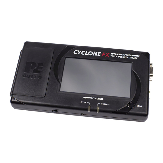
HARDWARE CYCLONE The following is an overview of the features and interfaces of the CYCLONE programmers. Many of these interfaces are labeled on the underside of the plastic case. Figure 3-1: CYCLONE Top View Touchscreen LCD The LCD Touchscreen displays information about the Cyclone’s configuration and the programming process, and also allows the user to navigate the Cyclone’s menus. -
Page 11: Cyclone System Power
Figure 3-2: CYCLONE Right Side View Cyclone System Power The CYCLONE programmer requires a regulated 6V DC Center Positive power supply with 2.5/5.5mm female plug. Cyclones derive power from the Power Jack located on the right end of the unit. The location of Cyclone System Power is shown in Figure 3-2. RS232 Communication (Serial Port) The CYCLONE provides a DB9 Female connector to communicate with a host computer... -
Page 12: Power Connectors
Figure 3-3: CYCLONE Front Side View 3.10 Power Connectors The CYCLONE programmers provide a Target Power Supply Input Jack and a Target Power Supply Output Jack with 2.5/5.5 mm Pin Diameter. The power jacks are connected or disconnected by two electromechanical relays. When connected, the Center Pin of the Target Power Supply Input Jack is connected to the Center Pin of the Target Power Supply Output Jack. -
Page 13: Control Expansion Port
Power Jumpers header must instead be left unpopulated. To reveal the Power Jumpers header, lift the access panel on the left end of the CYCLONE FX. The location is indicated as Power Jumpers in Figure 3-5. Please see CHAPTER 4 - TARGET POWER MANAGEMENT for the correct jumper settings for the Cyclone’s power management options. - Page 14 Figure 3-5: Target Headers & Power Jumpers (CYCLONE_UNIVERSAL_FX vs.CYCLONE_ACP_FX) Mechanical drawings are shown below whose dimensions are representative of the pin size and spacing of these headers. Note: The number of pins depicted in the mechanical drawings may differ from the Cyclone headers; the drawings are provided simply to demonstrate pin size and spacing.
-
Page 15: Target Headers For Part# Cyclone_Acp_Fx
Figure 3-7: Mini 10-Pin and Mini 20-Pin Keyed Header Dimensions 3.18 Target Headers For Part# CYCLONE_ACP_FX PEmicro Part# CYCLONE_ACP_FX features 3 ports labeled A-C. 3.18.1 PORT A: 10-Pin Keyed Mini Connector (Kinetis, S32 (ARM), other PEmicro-Supported ARM devices) 3.18.1.1 JTAG Pin Assignments The Cyclone provides a keyed 10-pin 0.050-inch pitch double row connector for ARM targets. - Page 16 3.18.1.2.1 High-Performance Communications If high-performance options are available for the selected device they will appear in the “Shift Frequency in MHz” drop-down. CYCLONE programmers are capable of high-performance communications when using certain ARM Cortex targets in SWD mode. Figure 3-9: High-Performance Options 3.18.2 PORT B: 20-Pin Keyed Mini Connector (Kinetis, S32 (ARM), other PEmicro-Supported ARM devices)
- Page 17 Figure 3-10: Communications Mode Selection 3.18.2.2.1 High-Performance Communications If high-performance options are available for the selected device they will appear in the “Shift Frequency in M Hz” drop-down. CYCLONE programmers are capable of high-performance communications when using certain ARM Cortex targets in SWD mode. Figure 3-11: High-Performance Options 3.18.3 PORT C: 20-Pin Debug Connector (Kinetis, S32 (ARM), other PEmicro-Supported ARM...
-
Page 18: Target Headers For Part# Cyclone_Universal_Fx
PIN 17 - NC* GND - PIN 18 PIN 19 - NC* GND - PIN 20 Note: *The pin is reserved for internal use within the PEmicro interface. SWD Mode is selected from the “Communication Mode” drop-down box in the Cyclone Image Creation Utility: Figure 3-12: Communications Mode Selection 3.18.3.2.1 High-Performance Communications... - Page 19 PIN 5 - GND NC* - PIN 6 PIN 7 - NC NC* - PIN 8 PIN 9* - NC RESET - PIN 10 *The pin is reserved for internal use within the PEmicro interface. SWD Mode is selected from the “Communication Mode” drop-down box in the Cyclone Image Creation Utility: Figure 3-14: Communications Mode Selection 3.19.1.2.1 High-Performance Communications...
- Page 20 clock and single bi-directional data pin. 20-Pin Keyed Mini Connector SWD Mode Pin Assignments PIN 1 - TVCC TMS/SWDIO - PIN 2 PIN 3 - GND TCK/SWCLK - PIN 4 PIN 5 - GND NC* - PIN 6 PIN 7 - NC NC* - PIN 8 PIN 9 - NC* RESET - PIN 10...
- Page 21 *The pin is reserved for internal use within the PEmicro interface. 3.19.3.1 BERG14-to-MICTOR38 Optional Connector PEmicro offers a 14-pin BERG to 38-pin MICTOR adapter, sold separately, that may be used on Port C of the CYCLONE FX. The PEmicro part number is BERG14-TO-MICTOR38. Figure 3-18: BERG14-TO-MICTOR38 Adapter (Sold Separately) 3.19.4 PORT D: 26-Pin Debug Connector (ColdFire V2/3/4) The Cyclone provides a standard 26-pin 0.100-inch pitch dual row 0.025-inch square header for...
- Page 22 The ColdFire adapter for Synchronous targets and ribbon cable for Asynchronous targets is pictured below: Figure 3-19: ColdFire Adapter (part# CABLE_CF_ADAPTER (Rev. B), for synchronous ColdFire targets, sold separately) Figure 3-20: ColdFire Ribbon Cable (for asynchronous ColdFire targets, included with Cyclone) 3.19.5 PORT E: 16-Pin Debug Connector (MON08) The Cyclone provides a 16-pin 0.100-inch pitch double row connector for MON08 targets.
- Page 23 adapter) The Cyclone provides a standard 6-pin 0.100-inch pitch dual row 0.025-inch square header for ColdFire V1, S12Z, 68(S)12(X), 68HCS08, RS08, and STMicroelectronics’ STM8 targets. The location of the this header is indicated as PORT F in Figure 3-5. The header uses the NXP standard pin configuration, listed here for reference: ColdFire V1, 68(S)12(X), 68HCS08, and RS08 Signals PIN 1 - BKGD...
- Page 24 3-5. Power MPC5xx/8xx BDM Pinout SRESET# DSCLK HRESET# DSDI DSDO *The pin is reserved for internal use within the PEmicro interface. 3.19.8 PORT H: 20-Pin Debug Connector (Kinetis, S32 (ARM), other PEmicro-Supported ARM devices) 3.19.8.1 JTAG Mode Pin Assignments The Cyclone provides a 20-pin 0.100-inch pitch double row connector for ARM targets. The location of the this header is indicated as PORT H under Part# CYCLONE_UNIVERSAL_FX in Figure 3-5.
-
Page 25: Ribbon Cable
Figure 3-22: Communications Mode Selection 3.19.8.2.1 High-Performance Communications If high-performance options are available for the selected device they will appear in the “Shift Frequency in MHz” drop-down. CYCLONE programmers are capable of high-performance communications when using certain ARM Cortex targets in SWD mode. Figure 3-23: High-Performance Options 3.20 Ribbon Cable... -
Page 26: Target Power Management
There are two different places Power Management is configured and they should be matched: first, by the jumpers on the CYCLONE FX, and second, in the setup of the programming image. The Cyclone jumpers are the most important because they are the physical connection to the target. - Page 27 Note: If these jumpers are not set correctly, the Cyclone will not function as intended. Target is powered independently Power provided externally (center +) and managed by Cyclone, power out to debug ribbon cable. Power provided externally (center +) and managed by Cyclone, power out to 2.5 mm output jack (center +) Power provided by Cyclone, power out to...
-
Page 28: Cyclone Setup
After the basic hardware setup, target power and voltage settings are also set in the creation of a SAP (stand-alone programming) image. At a minimum the SAP image contains all the commands to Erase, Program, and Verify a programming image. More sophisticated power selections in the SAP image can control the relays, target voltage, delays, and power down after SAP operations, as shown in the selection dialog. - Page 29 Figure 4-6: Power Provided by the Cyclone to the Debug Cable 4.2.3 External Power passed through the Cyclone and out 2.5 mm barrel port It is also possible to provide external power, passed through the Cyclone power relays, and back out to be available to power the target board externally.
-
Page 30: Setup Reminders
Figure 4-8: External Power Passed Through the Cyclone to the Debug Cable 4.2.5 Power provided by the Cyclone and out 2.5 mm barrel port In a slightly different scenario, the user may wish to have the Cyclone provide power, but power the target via an external connector on the target. -
Page 31: Touchscreen Lcd Menu
This chapter describes the Cyclone’s touchscreen LCD menu. Figure 5-1 shows an overview of the menu structure. Note: This menu will change as features are added to the CYCLONE FX, so if your menu does not match what is displayed here, please check PEmicro’s website, www.pemicro.com, for a user manual containing the latest LCD Menu operations information. -
Page 32: Main Menu
10. Status Window and Main Menu button (always shown). 11. Target voltage and/or current 12. Programming count & limit 5.1.3 Status Window The status window appears in the lower left corner of the home screen and displays the results of programming operations. - Page 33 Figure 5-2: Main Menu Structure User Manual For CYCLONE Programmers...
- Page 34 Displays current statistics, if any, for Image Programmed Count & Maximum Allowed, Errors Logged & Maximum Allowed, and Date Range Allowed. These limits can be set in the Image Creation Utility when using the CYCLONE FX. User Manual For CYCLONE...
- Page 35 Configure Network Settings Presents options that allows the user to view or edit various IP settings, toggle the IP settings between static and dynamic, and re-name the CYCLONE FX. 5.2.3.2.1 Show Current IP Settings This menu allows you to view the CYCLONE IP address, Mask, and Gateway, and MAC address.
- Page 36 5.2.3.2.3 Enable/Disable Dynamic IP Allows the user to toggle the Cyclone configuration between utilizing a Static IP address or a Dynamic IP address. The user must reset the CYCLONE after changing from Static to Dynamic or vice-versa. The reset button on the front side of the unit may be used. 5.2.3.3 Configure Time Settings (Cyclone Time / Real Time Clock) The CYCLONE...
- Page 37 that may be assigned to the AUX button are: 1. No Operation - No operation is assigned to the AUX button and it will not be displayed on the LCD screen. 2. Perform Verify Only - Verifies the data on the target device against the data in the pro- gramming image.
- Page 38 (FX Only) This menu selection allows the user to either Enable or Disable a barcode scanner connected to the Cyclone FX’s USB Extension Port. Select Enable to provide power to and turn on a connected barcode scanner. The Enable setting is persistent.
-
Page 39: Creating Programming Images
CREATING PROGRAMMING IMAGES The Cyclone Image Creation Utility is used to create programming images which may be loaded into the Cyclone. The user creates programming images based on data sets to be programmed and programming instructions which are all self contained. The next step is to download these programming images to the Cyclone via the GUI, Console, or SDK. - Page 40 **For a complete index of PEmicro-supported ARM Cortex devices, please view pemicro.com/ arm. The user may select the CPU Manufacturer from the drop-down list: Figure 6-2: CPU Manufacturer Selection The user may select the appropriate target architecture by clicking on "Select New Device." A Device Selection window will appear.
- Page 41 Figure 6-4: Security Settings - MPC55xx-57xx Only 6.1.2 Specify Programming Script Figure 6-5: Specify Programming Script This is a two-panel interface. The left panel provides a list of available programming functions. The right panel displays the ordering of the functions. To specify the programming algorithm for the target, double-click on the Choose Algorithm (CM) function in the left panel.
- Page 42 Figure 6-6: Load Programming Algorithm Dialog Select the programming algorithm that you wish to use. Similarly, to specify the S-Record to be programmed into the target, double-click on Specify S- Record (SS) in the left panel. This opens a dialog which allows you to select the appropriate S- Record.
- Page 43 Figure 6-7: Programming Functions Enabled Next, the user should add additional programming functions to complete the programming script. Figure 6-8: Programming Functions Complete User Manual For CYCLONE Programmers...
- Page 44 The Launch Script Wizard button prompts the user for a programming module, followed by an S- Record, and creates a default programming script. The user can then modify the programming sequence as needed. The Clear Script button will remove all programming commands from the right panel. The Move Up and Move Down buttons allow the user to manually re-sequence the order of the programming commands.
- Page 45 6.1.3.6 Program Bytes Prompts for a starting address, which must be in the module. You are then asked to enter in hexadecimal a byte to be programmed into the current location. Clicking the OK button will automatically advance to the next data byte location. 6.1.3.7 Program Words Prompts for a starting address, which must be in the module.
- Page 46 FX Special Features section of this window. Please refer to Section 6.1.7.2 - Use Barcode File, and for more information on using a barcode scanner with the Cyclone FX please see CHAPTER 11 - USING A BARCODE SCANNER TO SELECT AN IMAGE & INITIATE PROGRAMMING.
- Page 47 Cyclone programmer: from added ease when managing production to a desire to protect intellectual property. When using the CYCLONE FX, the “FX Special Features” section of the Cyclone Image Creation Utility allows you to specify one or more restrictions and tie them to specific programming images.
- Page 48 home screen by navigating in the touchscreen menu to Configure Cyclone Settings -> Configure Screen -> Configure Home Screen. For more information on how to configure the Cyclone’s home screen, see Section 5.2.3.5.4 - Configure Home Screen. 6.1.7.2 Use Barcode File PEmicro’s Cyclone programmers can be configured to use a bar code scanner (connected to the extension port) as part of the programming process.
-
Page 49: Manage Multiple Sap Images
previously been saved in order to create a new image. Manage Multiple SAP Images The Cyclone Control GUI, shown below in Figure 6-14, allows the Cyclone to store and manage multiple images in the Cyclone’s internal memory, and on any compatible SDHC cards that are loaded into the SDHC port. - Page 50 key on the keyboard, the image status will be changed to "Ready to Erase.” The image will be removed after "Apply Changes" is clicked. 6.2.2 Add/Remove Images From The Commit Changes Panels Once the images that you wish to load appear in the images tab, you must press “Apply Changes” to update the Cyclone accordingly.
-
Page 51: Cyclone Programmer Manual Control
CYCLONE PROGRAMMER MANUAL CONTROL The CYCLONE must be configured before it can serve as a Stand-Alone Programmer. The user may manually control the Cyclone via the LCD touchscreen menu and/or the Start button, or via PC software. See CHAPTER 8 - CYCLONE PROGRAMMER AUTOMATED CONTROL (CYCLONE CONTROL SUITE) for information on how to use the Cyclone Control Suite to configure, control, and automate Cyclone operations. -
Page 52: Operation Via Lcd Touchscreen Menu
Operation Via LCD Touchscreen Menu Once the CYCLONE is configured for stand-alone programming it may be operated by making selections from the touchscreen LCD menu. This section describes the menu functions that allow the user to easily execute stand-alone programming functions using the touchscreen LCD. Home Screen The home screen appears when the Cyclone is powered on, or when the Home button... -
Page 53: Status Window
12. Programming count & limit Status Window The status window appears in the lower left corner of the home screen and displays the results of programming operations. 7.4.1 Error Information Icon When the Cyclone experiences an error during programming operations, the Info icon will appear to the left of the Menu button (or AUX button, if configured). - Page 54 7.4.3.1.1 Launch Programming This allows the user to execute the programming function. The Cyclone will program the target device, if able, using the currently selected programming image. This is functionally equivalent to pressing the Start button. 7.4.3.1.2 Verify Data In Target Performs a verify function on the data that has been programmed into the target device.
-
Page 55: Cyclone Programmer Automated Control (Cyclone Control Suite)
Much of the cyclone control feature set works for all touchscreen Cyclones. Advanced features require a Cyclone-resident Advanced Automation License which comes built into the Cyclone FX and is available as an upgrade for all other touch screen Cyclones. -
Page 56: Cyclone Control Sdk
These features require an Advanced license only when using the SDK or Console (see below). The SDK and Console application provide the following Advanced features for all Cyclone FX units and any Cyclone upgraded with a resident Cyclone Control Advanced Automation License: •... - Page 57 The sample applications come with build scripts defined for ease of use. Simply run the scripts and you should be able to build the sample application without any modifications. The callable interface routines are defined in: INSTALLDIR\cycloneControl\controlsdk\examples\pascal\cyclone_control_api.pas INSTALLDIR\cycloneControl\controlsdk\examples\c\cyclone_control_api.h 8.2.2 Backwards Compatibility With Classic Cyclone Control API The “CycloneControlSDK.dll”...
- Page 58 INSTALLDIR\cycloneControl\controlsdk\examples\msvcsharp\visual_sap_control\cyclone_control _api.cs NI LabVIEW 2018 Projects INSTALLDIR\cyclone\cycloneControl\controlsdk\examples\labview2018\user.lib\CycloneControlS DK\CycloneControlSDK.lvlib INSTALLDIR\cyclone\cycloneControl\controlsdk\examples\labview2018\user.lib\CycloneControlS DK\VIs\*.vi The pre-built VIs that we provide include modifications for error handling using error clusters. Please visit our blog post “Automated Flash Programming with LabVIEW” for more information on how to develop your own LavVIEW project. 8.2.3.3 Initialization L oading the DLL (C/C++ Projects only)
- Page 59 8.2.3.4 Finalization Before closing the application, it is recommended that the session with the PEmicro hardware be terminated and the DLL unloaded from memory. These calls should always be made before the application closes: disconnectFromAllCyclones( ); unloadLibrary(); Note that the “unloadLibrary” call is only required for C/C++ applications. For the Delphi and C# example projects, the DLL is automatically unloaded when the application closes.
- Page 60 c. Retrieve the error code from the Cyclone unit to determine if the programming was successful. 8.2.3.7 External Memory Storage Support Some Cyclones support external memory storage. The Cyclone Control SDK and Cyclone Control Console both support images residing on external memory cards. The parameter “selectedMediaType”...
- Page 61 can be called. @returnvalue True if the load was successful, false otherwise. 8.2.4.2.2 unloadLibrary void unloadLibrary(void); This function unloads the DLL loaded with loadLibrary( ). This call should be made before the application starts to unload itself. 8.2.4.2.3 enumerateAllPorts void enumerateAllPorts(void); This function performs all necessary initialization in order to successfully communicate with a Cyclone.
- Page 62 Specifies the property of the Cyclone to return. The possible values are: @parameter • CycloneInformationation_IP_Address informationType • CycloneInfrmation_Name • CycloneInformation_Generic_port_number A pointer to a null-terminated string containing the property value of @returnvalue the specified Cyclone. 8.2.4.3 Cyclone Connecting / Disconnecting Calls 8.2.4.3.1 connectToCyclone uint32_t connectToCyclone(char *nameIpOrPortIdentifier) ;...
- Page 63 A null terminated string containing one or more Cyclone identifiers (name, IP address, or port number) delimited by commas. Example: USB1,209.1.10.2,Orion,COM1 If identifying by IP address, the string should be in the format of xxx.xxx.xxx.xxx, where xxx = @parameter nameIpOrPortIdentifierArray 0…255.
- Page 64 A Cyclone may have several independent programming images in its non-volatile internal or external memory. A programming image contains the programming algorithms, binary data, and programming sequence. This function instructs the Cyclone to start execution of an image. After invoking this call, the “checkCycloneExecutionStatus” function is used to poll the Cyclone until completion.
- Page 65 Checks to see if the Cyclone has completed a programming operation started with either the “startImageExecution” or “startDynamicDataProgram” functions. After this function returns with completed value, “getLastErrorCode” should be called to determine the programming result. A result of 0 will be returned even if a programming error has occurred or if communication with the Cyclone is lost.
- Page 66 @returnvalue The error code of the DLL or Cyclone 8.2.4.4.7 getLastErrorAddr uint32_t getLastErrorAddr(uint32_t cycloneHandle); If the “getErrorCode” function returns a non-zero value (indicating an error has occurred), this routine can be used to query the address where the error occurred. The handle of the Cyclone from which to request the error @parameter cycloneHandle address.
- Page 67 Used to select which image stored on the Cyclone to read the description from. The valid range of this parameter is from 1 to the total number of images in the Cyclone with the count starting from internal memory and @parameter imageId then external memory.
- Page 68 latest images on a server). The handle of the Cyclone that will have its images @parameter cycloneHandle erased This parameter selects between Cyclone internal @parameter selectedMediaType Flash (selectedMediaType = 1) or external memory (selectedMediaType =2). True if the erasure was successful @returnvalue False otherwise 8.2.4.5.4 eraseCycloneImage...
- Page 69 Set to True if you want the image to overwrite any existing images with the same description @parameter replaceImageOfSameDescription Set to False if you do not want the image to overwrite any existing images with the same description. An error will occur. A pointer to a null-terminated character @parameter aFile string which contains the full path to the...
- Page 70 8.2.4.5.8 setPropertyValue bool setPropertyValue(uint32_t cycloneHandle, uint32_t resourceOrImageId, char * categoryName, char *propertyName, char * newValue); This function changes the property of the Cyclone to the value specified. Only certain properties can be changed using this call. This function will return false if the property was not changed. Refer to the header file for a list of valid category and property names.
- Page 71 This function reads the firmware version of the selected Cyclone. @parameter cycloneHandle The handle of the Cyclone of which to read the firmware version. Returns a pointer to a null-terminated character string containing @returnvalue the firmware version. 8.2.4.6.2 cycloneSpecialFeatures bool cycloneSpecialFeatures(uint32_t featureNum, bool setFeature, uint32_t paramValue1, uint32_t paramValue2, uint32_t paramValue3, void *paramReference1, void *paramReference2);...
- Page 72 A pointer to a null-terminated character string which @parameter paramReference2 contains the full path to the specified SAP file. True if the CRC32 was read @returnvalue False otherwise @parameter featureNum CYCLONE_GET_IMAGE_SETTINGS_FROM_FILE Indicates whether the image file has been decoded. @parameter setFeature If previous operations has already decoded the file, then set it to true.
- Page 73 CYCLONE_GET_IMAGE_SCRIPT_FILE_FROM_FI @parameter featureNum Indicates whether the image file has been decoded. If @parameter setFeature previous operations has already decoded the file, then set it to true. Otherwise set it to false. @parameter paramValue1 Ignored, set it to 0. @parameter paramValue2 Ignored, set it to 0.
-
Page 74: Cyclone Control Console
@parameter paramValue3 Ignored, set it to 0. A pointer to an array containing the security code @parameter paramReference1 bytes. A pointer to a null-terminated character string @parameter paramReference2 containing the security type string (such as 'MON08', 'RENESAS', 'PPCNEXUS'). True if the security code was set @returnvalue False otherwise Cyclone Control Console... - Page 75 -putdynamicdata=[cyclone number],[address],[data] ONLY SUPPORTED BY CYCLONE FX OR THE CYCLONE CONTROL SUITE ADVANCED LICENSE. Performs programming of dynamic data with the selected Cyclone unit. [cyclone number] is the index of the connected Cyclone in the order in which it was entered. [address] is the starting memory address. [data] are the bytes of data to be programmed.
- Page 76 by image number.= -firmwareupdate=[firmware update mode] Set the firmware update mode to “auto”, “dontupdate”, “forceupdate”. The default mode is “auto.” -help Display a list of available commands. 8.3.3 Examples The commands should be separated by a space. Every command start with a “-” character, arguments follow the “=”...
-
Page 77: Cyclone Control Gui
8.3.3.4 Executing more than 1 image on the same Cyclone CycloneControlConsole.exe –cyclone=CycloneFX_1,CycloneFX_2 –launchimage=1 –launchimage=2 Two Cyclone units are connected via Ethernet and both Cyclone units execute their first image. Afterwards, the both Cyclones will execute their second image. This example is useful when the processor’s code is split into two separate images. For example, one image could contain the bootloader while the second image contains the main application code. - Page 78 Figure 8-2: Areas of the Cyclone Control GUI 8.4.1 The Connection Dialog Allows the user to specify a Cyclone to connect with, as well as specify the connection options. The utility will always automatically upgrade the firmware of a Cyclone if the firmware in the Cyclone is outdated.
- Page 79 Cyclone images, you can view and modify properties, you can modify licenses and see the Cyclone screen remotely. 8.4.2.1 The Images Tab The Images tab allows to modify the Cyclone images both in internal Cyclone memory and in external memory cards. To add a new image to the Cyclone, click on the “Add Image Internal” button and selected the image you want to add.
- Page 80 Figure 8-5: Changing Storage Area A blue image is not committed, disconnecting from the Cyclone before the “Apply Changes” button is clicked will discard any changes not committed. Erasing an image can be done by clicking on the trashcan icon at the left of the image, it can also be done by selecting the image and click the DELETE key on the keyboard.
- Page 81 Figure 8-7: Example: Edit Image Serial Number 8.4.2.2 The Properties Tab Figure 8-8: Properties Tab The properties tab shows all the network, Cyclone and image properties. It also shows properties for the supported features of the Cyclone. From this tab the Cyclone firmware and logic versions, the cyclone type, and the number of images are available.
- Page 82 Figure 8-9: Modifying Properties Clicking on the three dots or double clicking on the property value will bring up an edit window. Write the new property value and click “OK”, the property window will refresh and the value showed will be the updated value of the property. 8.4.2.3 The Remote Display Tab This tab will show the current display of the Cyclone.
-
Page 83: License
The Cyclone Control Suite software does not need a license to operate when using the standard features with any touchscreen Cyclone or when using advanced features with a Cyclone FX. When using the advanced automation features of the SDK or Console with non-FX cyclones, a “Cyclone Control Advanced Automation License”... - Page 84 thereby making possible stand-alone operations that may require licensing (such as the use of an SDHC card). Moreover, hardware licensing simplifies the management of personal computers by IT departments. PCs can be replaced, upgraded, or re-formatted, without any impact to the functionality and /licensing in place on PEmicro's hardware.
-
Page 85: Sap Image Compiler (Scripted Programming & Image Creation)
SAP IMAGE COMPILER (SCRIPTED PROGRAMMING & IMAGE CREATION) PEmicro’s Cyclone SAP Image Compiler, or CSAP, is an essential component in the Stand-Alone Programming (SAP) image creation process. It is designed to work in tandem with the Cyclone Image Creation Utility, by running in the background, but it can also be called directly by the user. The CSAP image compiler typically takes the .CFG file that was generated by the Image Creation Utility and uses it to locate and combine all of the components that will be included in the specific SAP image that is being created. - Page 86 HC08: CSAPMON08Z.exe MPC55XX-57XX: CSAPPPCNEXUSZ.exe RS08: CSAPRS08Z.exe S12Z: CSAPS12ZZ.exe STM8: CSAPWIZ01.exe 9.1.2 Filename and Additional Command-Line Parameters After specifying the executable, the user must also include the [filename] parameter, which represents the path and filename of the .CFG file. This is shown in blue in the example below. The user may also include one or more other command-line parameters.
-
Page 87: Configuration (.Cfg) File Contents
[imagecontent] This command-line parameter is a string that can be used to describe the SAP image, whether it is stored in a file or on the Cyclone. If the configuration com- mand :DESCRIBEIMAGE is also present in the .CFG file, this will be overwrit- ten. - Page 88 :NEWIMAGE :DESCRIBEIMAGE Test_K70 C:\PEMicro\cyclone\supportfiles\supportFiles_ARM\NXP\K7x\freescale _k70fn1m0m15_1x32x256k_pflash.arp C:\test\nxp\armcortex\mk_x_32_pflash_dflash_m5_05A0_1FFF.s19 ;Erase if not Blank ;Program Module ;Verify Checksum 9.2.2 Configuration Commands Configuration Commands are commands that will be executed at startup, before the programming process. You can see configuration commands used inside a sample .CFG file above in Section 9.2.1 - Sample .CFG File.
- Page 89 9.2.2.2 Trim Related (If supported) Configuration Commands 9.2.2.2.1 :CUSTOMTRIMREF n.nn Processors: All Desired internal reference clock frequency for the “PT; Program Trim” command. This frequency overrides the default internal reference clock frequency. Valid values for “n.nn” depend on the particular device being programmed. Please refer to the electrical specifications of your device for valid internal reference frequency clock range.
- Page 90 5/10/2018, 5/11/2018, and 5/12/2018. Does not allow it on any other dates. 9.2.2.4.3 :ERRORLIMIT n Processors: All Sets a limit to the number of errors that may occur while the Cyclone is programming devices. Once this limit has been reached, the Cyclone will no longer program devices until the error limit is removed or reset.
- Page 91 JTAG communications using the :USESWD 0 command/value. Specifies the index number of a device in the daisy chain. For more information on how to program or debug with a daisy chain setup, read: http://www.pemicro.com/blog/index.cfm?post_id=136 9.2.2.6.5 :JTAGPREIR n Processors: ARM, MAC7xxx Every JTAG device has an IR register that is a certain width in bits.
- Page 92 9.2.2.9 Connection Related (MPC5xxx, SPC5xxx) Processors 9.2.2.9.1 :DEBUGFREQUENCY n Processors: ARM, ColdFire, PPC, MAC7xxx, DSC, PPCNexus Specifies the communications frequency with the target device. Frequency in Kilohertz. 9.2.2.9.2 :UNCENSOR n Processors: PPCNexus This parameter should be used if 64-bit and 256-bit censorship passwords are needed to bypass security.
- Page 93 : Divide by 4 (usually and if applicable) 9.2.2.11.4 :BAUD n Sets the baud rate to n. Serial port connection only If :BAUD is specified, include :FORCEPASS followed by :SECURITYCODE. 9.2.2.11.5 :FORCEPASS Specifies that security should be passed on startup of the software instead of waiting for an EM (Erase Module) command.
- Page 94 example programming commands are at the bottom of the file. Note: The command parameter formats starting_addr, ending_addr, base_addr, and byte, word are hexadecimal by default. BM Blank check module. BR starting_addr ending_addr Blank check range. CM Choose module (algorithm) file. Note: Certain modules may require a base address to be specified EB starting_addr ending_addr Erase byte range.
-
Page 95: Csap Error Returns
When the user calls the CSAP executable that will reference this CFG file they will need to specify the values of these parameters on the command line. See the example below, where the first of these parameters is used to specify a programming algorithm (.SRP), the second an .S19 file, and the third a programming command (VM). - Page 96 6 - Starting address is not in module. 7 - Ending address is not in module or is less than starting address. 8 - Unable to open file for uploading. 9 - File write error during upload. 10 - Upload canceled by user. 11 - Error opening algorithm file.
- Page 97 53 - S-Records not all in range of module. (see "v" command line parameter) 54 - Error detected in settings on command line for port/interface 60 - Error calculating device CRC value 61 - Error - Device CRC does not match value given 70 - Error - CSAP is already running 71 - Error - Must specify both the INTERFACE and PORT on the command line 72 –...
-
Page 98: Ethernet Configuration
ETHERNET CONFIGURATION This section describes the mechanism used by the Cyclone device to transact data over an Ethernet network. It primarily focuses on the User Datagram Protocol (UDP), which is a popular method for sending data over a network when the speed of a data transaction is of more concern than the guarantee of its delivery. -
Page 99: Internet Protocol
10.3 Internet Protocol Once the network has been established, and the IP numbers have been assigned, data can be transacted over a network with one of several protocols. By far the most prevalent protocol is the Transmission Control Protocol (TCP), which runs on top of the Internet Protocol in what is collectively known as the TCP/IP protocol. -
Page 100: Cyclone Ip Setup Via Lcd Menu
device to match those of the network. 10.4.2 Connecting Cyclone-to-PC via an Ethernet cable In order to connect the Cyclone to a PC directly via an Ethernet cable, you need to use what is known as a cross-over cable. A cross-over cable, which is not provided by PEmicro, is normally used to connect two similar devices such as a PC to a PC, or a Hub to a Hub. -
Page 101: Configuring Cyclone Network Settings Using The Cyclone Control Gui
• MAC Address If you are in Static IP mode, these settings (excluding the MAC address) may be changed by tapping on them. In this case a tap will take you to the Edit menus. If you are in Dynamic IP mode, tapping will show a message that the Cyclone settings cannot be changed. - Page 102 Figure 10-1: Cyclone Control GUI: Properties Tab Selected From this tab, all Cyclone and Network properties can be accessed. Some of this properties are modifiable, including all the properties needed for network configuration. A property that can be edited will show three dots to the right of the property when you select it by clicking on its box. You can click on the three dots or double click on the property value to bring up the edit window.
- Page 103 Figure 10-2: Dots Displayed At Right When Property Selected Figure 10-3: Edit Property Window Once the "OK" button is pressed, the values of the property will be updated in the Cyclone and the value of the property in the Cyclone Control GUI will be refreshed showing the new value. User Manual For CYCLONE Programmers...
-
Page 104: Using A Barcode Scanner To Select An Image & Initiate Programming
Simply scan the bar code and programming will be initiated. The Cyclone FX scans the barcode and checks all resident images for a barcode match. If exactly one match is found, the image is selected and used to program the target. If no matches are found, or multiple matches are found, an appropriate error is reported. -
Page 105: Potential Benefits Of Programming Via Barcode Scan
Figure 11-1: CYCLONE FX With Barcode Scanner 11.3 Potential Benefits Of Programming Via Barcode Scan The use of a barcode scanner as part of the manufacturing process can boost productivity and reduce human error. When the user scans a barcode to select and launch the programming sequence, it frees that user from having to know any details about the product being programmed;... -
Page 106: Enabling Barcode Scanner In Cyclone Menu
11.4 Enabling Barcode Scanner In Cyclone Menu To use the barcode scanner with a CYCLONE FX, the scanner must first be enabled in the Cyclone menu by navigating to “Configure Cyclone” and then “Configure USB Host Device.” The user should click on “Enable USB Scanner”. The barcode scanner's instructions should be consulted to understand how to put the scanner into Wedge (keyboard emulation) mode, and to make sure that it terminates the barcode with a CR (carriage return) character. - Page 107 demonstrates one simple approach to creating a barcode; there are many methods available. Figure 11-3: Create Prototype Barcode In this example, the “P&E MICRO” portion of the prototype barcode exists in every bar code the company produces - in this case, header characters that identify the company. Also for this example, a product identifier “TEST1”...
- Page 108 The next test will check whether the scanned barcode matches the product identifier “TEST1” exactly. The user should click the small down arrows for the "TEST1" characters to bring them into the Char test section. See Figure 5. Figure 11-5: Create Char Test For "TEST1" The "1"...
-
Page 109: Creating A Barcode Test: In Depth
Figure 11-7: Completed Barcode Test This completes setup of the barcode test. The user should now click on “Save File As” on top and name the test “Test1_barcodetest.bar”. This test is now ready to be added to a programming image using the Cyclone Image Creation utility. 11.6 Creating a Barcode Test: In Depth This section is an in-depth exploration of how to use the Barcode Test Generator utility to create a... - Page 110 Figure 11-8: Typical Barcode Test Generator Main Screen On Startup 11.6.1 Barcode Test Creation and Testing Process A Barcode Test can be easily created and tested using the following 8 simple steps which are explained in paragraphs following the list below: 1.
- Page 111 1. By simply typing in ascii characters or pairs of hexadecimal characters. 2. By copying a string of highlighted characters by Ctrl-C / Ctrl-V method. 3. By scanning in a string of characters starting at the current cursor position. Figure 11-9: Typical Sample Entry Screen Section Figure 11-1 shows a typical entry screen section.
- Page 112 tested. Figure 11-10: Sample Characters copied to Char Test Section Simply clicking on the down arrows between the Sample and Char Test(TYPE): Sections of the screen transfers the corresponding character to the test section. The transferred characters are shown as ASCII characters along with an associated type. The ASCII characters in the Char Test Section represent transferred value and do not change when the Sample characters are edited.
- Page 113 clicking on “click here to add type.” If clicked, one of the similar windows shown in Figure 11-12.a, Figure 11-12.b, or Figure 11-12.c is opened. Types can also be efficiently copied to other blocks as per Section 11.6.6.2 - Ctrl-C / Ctrl-V Char Test(TYPE): and Range Copying. Figure 11-12: a) On Click Add Figure;...
- Page 114 Figure 11-14: a) Compressed Types for “Rev-“ Test Character; b) MT Type Change for “Rev-“ Test Character 11.6.1.3.4 Type Changing Errors When initially created, a Char Test type always matches the type of character in the corresponding Sample field. However, changing a Char Test type or a Sample character can case an error. Errors are always indicated by changing appropriate background colors to red.
- Page 115 Figure 11-16: Transfers from Char Test to Range-1 In Figure 11-16, the NUmeric (NU) characters were transferred to the Range-1 test using the down Arrows. Only types with contiguous character sets can be transferred this way. When contiguous types are transferred, the upper and lower bounds are set to the types maximum and minimum values for convenience.
- Page 116 11.6.1.6 Press the DO TEST button to test Sample(ascii) characters against all tests. When developing Barcode tests, it is necessary to frequently test to assure that the tests being generated corrects select the appropriate standalone programming (SAP) image. Clicking on the DO TEST button, as shown in the Figure 11-19 control area of this program, causes the CharTest(TYPE): and both Range tests to be run if they exist.
- Page 117 The tests created can be saved (See Section 11.6.5 - Saving and Loading Barcode Test (.bar) Files.) for later inclusion in a Cyclone FX programming SAP image using PEmicro’s image creation utility [1]. The saved tests can also be reloaded for correction or as the base for creating other tests.
- Page 118 11.6.3 Enabling/Disabling A Barcode Scanner To enable a barcode scanner that is connected to the Cyclone FX’s USB Extension Port, go to: Menu -> Configure Cyclone -> Configure USB Host Device -> Enable USB Scanner This setting is persistent; the scanner will be powered and turned on when the Cyclone is powered, until the scanner is disabled.
- Page 119 11.6.4 Ranges and Range Testing Testing is done in two steps First, if any Char Test(TYPE): characters are specified a Character Type test is done as indicated in Section 11.6.4.1 - Character Type Testing. Then, if either Range-1 or Range-2 has entries, a Range test is done as indicate in Section 11.6.4.2 - Range Testing.
- Page 120 The current information on the program main screen can be saved to a Barcode Test (.bar) file for two reasons. First, so the tests can be used by PEmicro’s Cyclone FX, Standalone programmer. Second, so the information can be loaded back into this program for modification, further testing of the tests themselves, or to assist in the creation of new tests.
- Page 121 Figure 11-25: Save PEmicro JSON File Window 11.6.5.3 Loading a Barcode Test (.bar) File PEmicro JSON Barcode Test (.bar) Information can be loaded into this utility so it can be edited further or to test other barcodes. To load a Barcode Test (.bar) file, click on the Load File button in the control area of the main screen.
- Page 122 into a Sample box. Characters which are selected are indicated by changing the font color to red. Once a set of characters has been selected, they are copied into Char Test(TYPE): entries by clicking on the Char Test(TYPE): button. Bulk Copy turns of the selected character font highlighting.
- Page 123 Figure 11-31: Highlighted Char Test(TYPE): entries for Bulk Copy to Range entries Figure 11-32: After Char Test(TYPE): entries Bulk Copy to Range-1 entries 11.6.6.1.4 Turning Off Bulk Copy Clicking on the text button in the program control area disables Bulk Set Bulk Copy Copying.
-
Page 124: Adding A Barcode Test Into A Programming Image
Figure 11-33: Program Control Area Each time the Inc Numb Chars button is clicked, an additional character space is added to the display up to a maximum of 64. Also, the width of the program window is increased to accommodate the added character spaces. The number of display characters is only reset to 36 by restarting the utility. -
Page 125: Troubleshooting
Figure 11-36: FX Special Features (Add Barcode File To Image) After the programming image is stored in the CYCLONE FX, it is ready to use. When a barcode is scanned the Cyclone will encounter this programming image, which will prompt it to test for the exact string “P&E MICRO-TEST1”... - Page 126 One Image passes barcode test Image number 5 selected to execute Success, image selected and program command sent ---Scanner Test Log Finished--- User Manual For CYCLONE Programmers...
-
Page 127: Automatic Serial Number Mechanism
AUTOMATIC SERIAL NUMBER MECHANISM When producing a microcontroller- or microprocessor-based product, it is often useful to program a unique serial number into the permanent memory (FLASH) of the product. PEmicro has developed a serial number mechanism to automate this process. Each time you issue a serialization command in the programming software, the current serial number is programmed at a specified address. - Page 128 Figure 12-1: Serialize Main Screen 12.2.1 Serial Number File On startup, the Serialize program will automatically open the last file saved. If no file has been saved, it will default to blank. • Reset Button - Lets you reset to a screen with only a single serial number byte defaulted to binary (00), Hex Address 00000000.
-
Page 129: Changing Serial Number Format To Little-Endian
• Up Arrow Click - Counts the serial number up. • Down Arrow Click - Counts the serial number down. 12.2.4 Serial Number Bytes as Hex There is one display column for each byte in the serial number shown as printable ASCII characters. -
Page 130: Serialize Utility Example
saved (Save Button). The new serial number is initialized with one (1) byte of binary. 12.3.2 SAVE Pops up a Save dialog with the current serial number being edited into the file name and path as shown in the Serial Number File window. If a file name has not been provided, a dialog will pop up to allow the user select a file name. - Page 131 CS serial_file1.ser CS serial_file2.ser CS serial_file_3.ser CM algorithm_file_2 SS object_code_2 CS serial_file4.ser CS serial_file5.ser User Manual For CYCLONE Programmers...
-
Page 132: Troubleshooting
TROUBLESHOOTING This section answers some common questions that should help the user with various aspects of CYCLONE operation. 13.1 My Cyclone Is Non-Responsive, Is There A Way I Can Try To Re-Activate It? It is possible that the issue is outdated firmware. In this case, you may wish to use bootloader mode to update the Cyclone firmware and then try to re-start the Cyclone. -
Page 133: When Trying To Install The Cyclone Software, A Popup Wdreg Error Occurs Telling Me That There Are Open Devices Using Windriver
Where: [old_SAP_path] The relative or full path to the SAP file. Usually has the .SAP file extension. [new_SAP_path] Optional parameter where the user can specify a relative or full path to dump the output of the conversion. If path and file name matches the input, then the output file will replace the input file. -
Page 134: Error Codes
ERROR CODES The CYCLONE will indicate errors using the following codes. Please contact PEmicro if instructed or if you are unsure of the specific meaning of an error code. 14.1 Debug Mode Communication Related Errors $0001: No target device response. $0002: Invalid target device response. -
Page 135: Sap Operation Related Errors
$0061: Undefined header operation $0062: Operation in algorithm header has failed. 14.4 SAP Operation Related Errors $0080: SAP operation is not supported. $0082: Target type mismatch $0083: SAP operation canceled $0084: Running algorithm failure 14.5 SAP Blank Check Range and Module Related Errors $1001: Blank Check is not supported by this algorithm. -
Page 136: Sap Verify Checksum Related Errors
14.8 SAP Verify Checksum Related Errors $4001: Verify Checksum not supported $4002: VC failed, invalid algorithm was used $4003: VC operation failed or was canceled $4011: VV command not supported $4012: VV failed, invalid algorithm was used $4013: VV operation failed or was canceled 14.9 SAP Verify Range and Module Related Errors $5003: Error during verifying module. -
Page 137: Operation Security Related Errors
$9002: Error: Exceeds image specified Error Limit $9003: Error: Exceeds Image specified Date Range $9004: This programming image has usage restrictions enabled. Requires Cyclone FX hardware. $9005: Error: This programming image has barcode enabled. Requires Cyclone FX hardware. $9006: Error: This programming image has command RT Run Code in Test/Calibration Mode. -
Page 138: Download Count Related Errors
$B005: Error during serial number structure update $B006: Error: Serial Number structure was not found. $B007: Error: Serial Number structure is invalid $B008: Error programming Serial Number to target. $B009: Error obtain Serial Number from storage. 14.16 Download Count Related Errors $C001: Error erasing the download counts storage $C002: Error writing the download counts $C003: Download counts is over the limit, up to 255 can be supported at a time... -
Page 139: Technical Information
TECHNICAL INFORMATION This section contains information about various physical, mechanical, electrical, etc. aspects of the CYCLONE programmers, part # CYCLONE_ACP_FX and part # CYCLONE_UNIVERSAL_FX. The information applies to both CYCLONE part numbers unless specified. 15.1 Life Expectancy Start Button: 1 Million Press Rated 15.2 Electrical Specifications Input Voltage: DC 6V...
Need help?
Do you have a question about the CYCLONE FX and is the answer not in the manual?
Questions and answers