
Related Manuals for INVT iMars


Summary of Contents for INVT iMars
- Page 1 Operation Manual iMars Grid-tied Solar Inverter INVT Solar Technology (Shenzhen) Co., Ltd.
-
Page 3: Preface
The use of iMars series grid-tied solar inverters must comply with local laws and regulations on grid-tied power generation. The manual needs to be kept well and be available at all times. -
Page 4: Table Of Contents
Contents Contents Preface ..............................1 Contents..............................2 1 Safety precautions ..........................4 1.1 Icons ............................5 1.2 Safety guidelines ........................5 1.2.1 Delivery and installation........................6 1.2.2 Grid-tied operation ..........................7 1.2.3 Maintenance and inspection ......................7 1.2.4 What to do after scrapping .......................8 2 Product overview.......................... - Page 5 Contents 4.4.1 Connection of solar modules....................27 4.4.2 AC connection ..........................29 5 Operation ............................30 5.1 Inspection before operation ....................31 5.2 Grid-tied operation ........................ 31 5.3 Stopping..........................32 5.4 Daily maintenance ......................... 32 5.4.1 Regular maintenance ......................... 32 5.4.2 Maintenance guide ........................
-
Page 6: Safety Precautions
Safety precautions iMars grid-tied solar inverters 1 Safety precautions iMars series grid-tied solar inverters are designed and tested strictly in accordance with relevant international safety standards. As an electrical and electronic device, all relevant safety regulations must be strictly complied during installation, operation, and maintenance. -
Page 7: Icons
Safety precautions iMars grid-tied solar inverters 1.1 Icons This manual provides relevant information with icons to highlight the physical and property safety of the user to avoid device damage and physical injury. The icons used in this manual are listed below:... -
Page 8: Delivery And Installation
Ensure that DC and AC side circuit breakers have been disconnected and wait at least 5 minutes before wiring and checking. Note: Technical personnel who can perform installation, wiring, commissioning, maintenance, troubleshooting and replacement of the iMars series grid-tied solar inverters must meet the following requirements: ... -
Page 9: Grid-Tied Operation
Ensure reliable installation and electrical connection. Note: iMars series grid-tied solar inverters are only for crystalline silicon solar modules. 1.2.2 Grid-tied operation Only qualified electricians are allowed to operate the inverter under the permission of local power departments. -
Page 10: What To Do After Scrapping
Safety precautions iMars grid-tied solar inverters measures because of the electrostatic sensitive circuits and devices in the inverter. Do not use parts and components not provided by our company during maintenance. Restart the inverter after settling the fault and problem which may affect the safety and performance of the inverter. -
Page 11: Product Overview
Product overview iMars grid-tied solar inverters 2 Product overview This chapter mainly describes the appearance, packaging accessories, name plate, technical parameters and other information of iMars series grid-tied solar inverters. -
Page 12: Solar Grid-Tied Power Generation System
AC energy which has the same frequency and phase with the public grid by grid-tied solar inverters, and then be fed to the grid. iMars series grid-tied solar inverters are only applied in solar grid-tied power generation system and its DC input are only composed of crystalline silicon solar modules whose negative and positive poles are not grounded. - Page 13 Product overview iMars grid-tied solar inverters Figure 2.2 Type of grid...
-
Page 14: Products Appearance
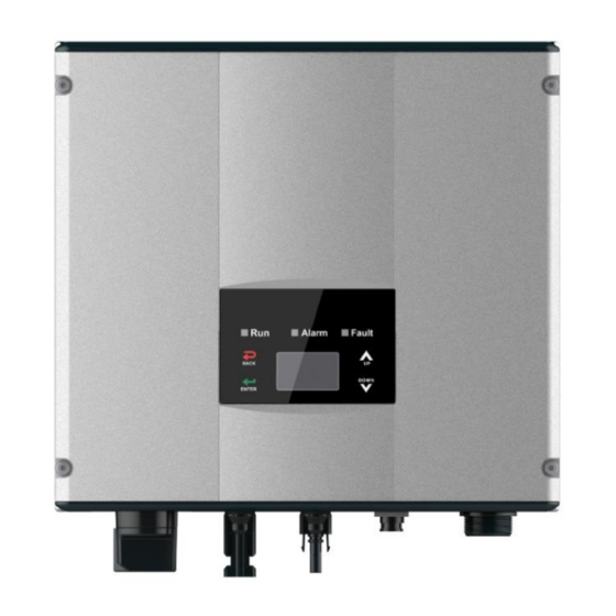
Product overview iMars grid-tied solar inverters 2.2 Products appearance Figure 2.3 Products appearance Table 2-1 Parts instruction Name Instruction Cover LED display panel LED indicators On –off of the DC input (optional) DC switch DC input port For the connection of solar modules... -
Page 15: Nameplate
Product overview iMars grid-tied solar inverters 2.3 Nameplate Inverter nameplate as shown in Figure 2.4 Figure 2.4 Inverter nameplate (1)Trademark and product type (2)Model and important technical parameters (3)Certification system of the inverter confirming (4)Serial number, company name and country of origin. -
Page 16: Products Modules
CQC certification mark. The inverter is certified by CQC. EU WEEE mark. Cannot dispose of the inverter as household waste. 2.4 Products modules Table 2-2 Models of iMars grid-tied solar inverter Product name Model Rated output power Single-phase (L, N, PE) -
Page 17: Dimensions And Weight
Product overview iMars grid-tied solar inverters 2.5 Dimensions and weight Figure 2.5 Inverter dimensions Table 2-3 Inverter dimension and net weight Model H (mm) W (mm) D (mm) Net weight (kg) MG750TL / MG1KTL / MG1K5TL / MG2KTL / MG3KTL... - Page 18 Product overview iMars grid-tied solar inverters Figure 2.6 Paper packages dimension Table 2-4 Packages dimension and gross weight Gross Packagin Model (mm) (mm) (mm) weight (kg) g Material MG750TL / MG1KTL / MG1K5TL / MG2KTL / Paper MG3KTL MG4KTL / MG4K6TL /...
-
Page 19: Storage
Storage iMars grid-tied solar inverters 3 Storage If the inverter is not put into use immediately, the storage of inverter should meet the following requirements: Do not remove the outer packing. The inverter needs to be stored in a clean and dry place, and prevent the erosion of dust and water vapor. -
Page 20: Installation
Installation iMars grid-tied solar inverters 4 Installation This chapter describes how to install the inverter and connect it to the grid-tied solar system (including the connection between solar modules, public grid and inverter). Read this chapter carefully and ensure all installation requirements are met... -
Page 21: Unpacking Inspection
Installation iMars grid-tied solar inverters 4.1 Unpacking inspection The inverter has been thoroughly tested and rigorously checked before delivery, but damage may still occur during transportation. Before unpacking, check carefully whether the product information in the order is consistent with that on the nameplate of the package box and whether the product package is intact. - Page 22 Installation iMars grid-tied solar inverters Table 4-1 Detailed delivery list of single-phase inverter Name Quantity MG750TL / MG1KTL / MG1K5TL / MG2KTL / MG3KTL / MG4KTL / MG4K6TL / MG5KTL / MG3KTL-2M / MG4KTL-2M / MG4K6TL-2M / MG5KTL-2M / MG6KTL-2M...
-
Page 23: Before Installation
Installation iMars grid-tied solar inverters 4.2 Before installation 4.2.1 Installation tools Table 4-2 Tools list Installation tools Instruction Marking pen Mark the installation hole Electrodrill Drill in the bracket or wall Hammer Hammer on the expansion bolts Monkey wrench Fix the installation bracket... -
Page 24: Cable Specification
Installation iMars grid-tied solar inverters Figure 4.2 Installation space Ensure there is sufficient space for heat-releasing. In generally, below space requirement should be met: Table 4-3 Detailed installation space Minimum clearance Lateral 200mm 450mm Bottom 450mm Figure 4.3 Installation position ... -
Page 25: Miniature Circuit Breakers
Installation iMars grid-tied solar inverters to corresponding inverter should be fulfilled: Table 4-4 Cable specifications DC side AC side Mini cross-sectional cross-sectional Min cross Model area mm² area sectional area mm² mm²(length≤50 (Length>50m) N/PE MG750TL / MG1KTL / MG1K5TL / MG2KTL /... -
Page 26: Mechanical Installation
Installation iMars grid-tied solar inverters 4.3 Mechanical installation The material for fixing the inverter and the installation mode vary with the different installation sites. It is recommended to install the inverter vertically to the firm wall or metal bracket. Here we take wall installation as an example to introduce the installation matters of the inverter. - Page 27 Installation iMars grid-tied solar inverters Table 4-7 Instruction of installation bracket Structure instruction Installation holeΦ8 Assembling bolt hole M5 Installation steps: (1) Firstly, take down the installation bracket from the package. (2) Place the bracket at the appropriate height and position on the wall. Mark the punching position according to the fixing hole.
-
Page 28: Electrical Installation
Installation iMars grid-tied solar inverters 4.4 Electrical installation This section describes the electrical connection related content and related safety precautions. Figure 4.7 is the schematic diagram of the photovoltaic grid-connected system. Figure 4.7 PV grid-connected system diagram Electrical connection must be carried out by professional technicians as wrong operation may cause damage to the device, physical injuries or even death during system operation. -
Page 29: Connection Of Solar Modules
2.5-3Nm. The wiring of negative pole is the same as that of the positive pole. Ensure the poles of solar modules are well connected with the connectors; The PV string connected to iMars series inverter must adopt the DC connector configured especially for the inverter, do not use other connection devices... - Page 30 Installation iMars grid-tied solar inverters After the DC connector is connected, use a multimeter to measure the voltage of the DC input string, verify the polarity of the DC input cable, and ensure that the voltage of each string is within the allowable range of the inverter, as shown in Figure 4.9.
-
Page 31: Ac Connection
Installation iMars grid-tied solar inverters 4.4.2 AC connection Figure 4.10 AC connection of single-phase inverter AC connection steps of single-phase inverter: (1) Before connecting the single-phase AC grid cable to the inverter, take lightning and short circuit protection measures in accordance with the local electrical safety codes;... -
Page 32: Operation
Operation iMars grid-tied solar inverters 5 Operation This chapter describes detailed operation of the inverter which involves the inspection before operation, grid-tied operation, stopping and daily maintenance of the inverter. -
Page 33: Inspection Before Operation
Operation iMars grid-tied solar inverters 5.1 Inspection before operation The following items must be checked strictly before running the PV grid-connected inverter (including but not limited to): (1) Ensure the installation site meet the requirement mentioned in section 4.2.2 for easy installation, removing, operation and maintenance;... -
Page 34: Stopping
5.4 Daily maintenance In solar PV grid-connected power generation system, iMars series grid-connected solar inverter can realize grid-connected power generation and stop/start operations automatically day and light in whatever seasons. In order to safeguard and prolong the service life of the inverter, it is necessary to carry out daily maintenance and inspection on the inverter besides using the inverter strictly according to this manual. -
Page 35: Maintenance Guide
Operation iMars grid-tied solar inverters Maintenance Maintenance Maintenance methods contents cycle Use real-time monitoring software to read inverter running data, regularly back up all Store the operation inverter running data and stats. Check the Once each quarter data monitoring software and inverter LCD screen to make sure the parameters are set correctly. -
Page 36: Display Panel
Display panel iMars grid-tied solar inverters 6 Display panel This chapter describes the panel displaying and how to operate on the panel, which involves the LCD display, LED indicators and operation panel. -
Page 37: Led Indicators
Display panel iMars grid-tied solar inverters 6.1 LED indicators There are three LED indicators on the panel: (1) “Run”, operation indicator, green; (2) “Warn” recoverable fault indicator, yellow; (3) “Fault”, unrecoverable fault indicator, red. The inverter state includes 6 states of stand-by, self-inspection, power generation, recoverable fault and unrecoverable fault;... -
Page 38: Operation Panel
Display panel iMars grid-tied solar inverters Inverter state LED indicators Description (1) Inverter stand-by. Temperature abnormal(E006); Warn (2) Inverter stand-by. DC input fault (E001); Fault Yellow indicator keeps on, others off Hardware or software fault (E003, E004, E005, E008, E009, E011, E013 or E015). De-couple the inverter Warn from the system before maintenance. -
Page 39: Lcd Screen
Display panel iMars grid-tied solar inverters 6.3 LCD screen Figure 6.1 Operation panel All information is displayed on the LCD screen. The background illumination of LCD screen will go out to save power if there is not button operation in 15 seconds. But it can be activated by pressing any button. -
Page 40: Functions Operation
Display panel iMars grid-tied solar inverters (3) State display area displays current running state of the inverter, which can display “self-inspection”, “grid-connected power generation”, “alarm”, “fault”, “OFF” state; (4) Dynamic fault code and menu entrance. When the state display area displays “alarm” or “fault”, the dynamic fault code area will display corresponding fault code (display up to 8... -
Page 41: Statistics
Display panel iMars grid-tied solar inverters through the historical information, press “ESC” to return. The number on the upper right corner of the first row is the number of historical record, the 2 row (as shown in Fig 6.5) displays the date... - Page 42 Display panel iMars grid-tied solar inverters S e t u p M e n u A d d r e s s C a s h / p r i c e D a t e / T i m e L a n g u a g e Figure 6.7 Setting information...
- Page 43 Display panel iMars grid-tied solar inverters...
- Page 44 Display panel iMars grid-tied solar inverters Table 6-3 Parameters setting Setting item LCD display Instruction Enter into the interface and edit the data through “ ” or “ ”. And then press R S 4 8 5 A d d r e s s...
- Page 45 Display panel iMars grid-tied solar inverters Setting item LCD display Instruction The default password is “0000”; the user can enter into the setting interface without password. If the password is not “0000”, the user can enter into the setting interface with password.
- Page 46 Display panel iMars grid-tied solar inverters Setting item LCD display Instruction mode” is the parallel MPPT of Track A and Track B. The default mode is “independent”. The input mode setting is invisible if the inverter is in power generation. It is only available during DC power on and AC power off.
- Page 47 Display panel iMars grid-tied solar inverters Setting item LCD display Instruction Input password The password is needed when enter into 0000 the interface of “Set power”. Get the password from the supplier if necessary. There are 3 submenus: ①P-Lmt Mode:...
- Page 48 Display panel iMars grid-tied solar inverters Setting item LCD display Instruction Input password 0000 Run Param UV Volt OV time UV time UF Freq OV Volt UF time ACUV Volt(phase volt) Password is required when enter into the 184V interface of “Run Param”. Get the password from the supplier if necessary.
- Page 49 Display panel iMars grid-tied solar inverters Setting item LCD display Instruction Input Password 0000 Run Param UV volt 1 OV time 1 UV time 1 UF Freq 1 OV volt 1 UF time 1 ACUV Volt(phase volt) 115V ACUV Time 00.04s...
-
Page 50: System Information
Display panel iMars grid-tied solar inverters 6.4.5 System Information Press “ ” and “ ” in the main interface to select “System Information”, and then press “ENT” to view the parameters which is shown in Figure 6.8. System Information Part No . -
Page 51: Grid Certification Choice
Display panel iMars grid-tied solar inverters Refer to the table below for detailed information. Table 6-4 Inverter control Control item LCD display Instruction Control the “On/Off” through the panel. Press “ ” and “ ” in the control O n / O f f C t r l On/Off interface to select the operation. - Page 52 Display panel iMars grid-tied solar inverters Press the “ ” or “ ” button to select the country (refer to the below table), press the ENT button to complete the setting. After finish the country setting, please follow the user manual required with the proper use of inverter.
- Page 53 Display panel iMars grid-tied solar inverters V - p v 1 : 0 0 0 . 0 V M a i n M e n u I - p v 1 : 0 0 0 . 0 A M o n i t P a r a m...
-
Page 54: Monitoring Communication
This chapter describes the communication connection of inverter and monitoring system (Industrial master, private computers, smart phones and so on). The standard communication mode of iMars grid-tied solar inverter is RS485 which includes “RS485-M” and “RS485-S” ports. The RS485-M ports can communicate with private computers, smart phones and so on. -
Page 55: Standard Communication
Fig 7.4; Figure 7.4 Detailed connection (2) According to Table 7-1, connect the communication connector pinout and the user's device, make sure the connection is correct. (3) Please download the monitoring software “iMars WinExpert” and its operation instruction from our website. -
Page 56: Optional Communication
Display panel iMars grid-tied solar inverters 7.2 Optional communication The optional communication modes include the Ethernet, WiFi, GPRS and ENET, which also need corresponding communication parts and components as shown in Table 7-2.All operation parameters of the inverter are output from port “RS485-M” to the communication devices, finally transmitted to the monitoring system as standard Ethernet, WiFi, GPRS and ENET signal. -
Page 57: Troubleshooting
Troubleshooting iMars grid-tied solar inverters 8 Troubleshooting This chapter describes the fault alarm and fault code for quick troubleshooting. - Page 58 Troubleshooting iMars grid-tied solar inverters Table 8-1 Fault code Fault code Message Instruction Fault analysis PV1 undervoltage A001 Input UV Input undervoltage PV2 undervoltage A002 Bus UV Bus undervoltage DC input Low voltage of the public A003 Grid UV AC undervoltage...
- Page 59 Troubleshooting iMars grid-tied solar inverters Fault code Message Instruction Fault analysis E013 Eeprom Memory error Internal memory error High DC injection during AC E014 Dc inject High DC injection output E015 OutputShort Output short-circuit Output short-circuit E018 Input OC Input overcurrent...
- Page 60 Troubleshooting iMars grid-tied solar inverters If any problem, please contact with the supplier and provide following information: Model of the inverter: Serial No. of the inverter: System version:——version 1: ——version 2: ——MCU software version: Fault code:...
-
Page 61: Contact Us
Contact us iMars grid-tied solar inverters 9 Contact us China· Shenzhen INVT Solar Technology (Shenzhen) Co., Ltd. Address: Room 504, No. 7 Building, Gaofa Scientific Industrial Park, Longjing, Nanshan District, Shenzhen, China Service hotline: +86 400 700 9997 E-mail: solar-service@invt.com.cn INVT group website: www.invt.com... - Page 62 Technical parameters iMars grid-tied solar inverters Appendix Technical parameters of single phase grid-tied solar inverter Single-phase Model MG750TL MG1KTL MG1K5TL MG2KTL MG3KTL MG4KTL MG4K6TL MG5KTL MG3KTL-2M MG4KTL-2M MG4K6TL-2M MG5KTL-2M MG6KTL-2M Max. DC voltage (V) Starting voltage (V) MPPT voltage range(V)
Need help?
Do you have a question about the iMars and is the answer not in the manual?
Questions and answers
Hi, i've got a new INVT XG30KTR from China and i cant sart it , how i have to do , do i need something eslse like USB or anything else with it
To start the INVT XG30KTR inverter:
1. Disconnect the DC and AC side circuit breakers before wiring.
2. Wait at least 5 minutes after disconnecting before performing any wiring or checks.
3. Ensure the inverter is reliably grounded.
4. Power on the inverter using DC input.
5. On first startup or after restoring factory settings, select the country on the LCD screen.
You do not need a USB to start the inverter. All initial setup is done using the LCD screen and buttons.
This answer is automatically generated
@Mr. Anderson
voici l'autre image
je vous envoie l'image du LCD
Bonjour, ça ne marche pas toujours voila ce que le LCD montre : RUNNING ERROR; GRID EN 50549; FAULT 31-03; F 31-03 , je vous met en photo l'ecran
The error message "RUNNING ERROR; GRID EN 50549; FAULT 31-03; F 31-03" refers to a grid-related fault according to the EN 50549 standard. It indicates the inverter has detected a fault condition related to grid parameters that do not comply with the required standard, such as voltage, frequency, or other grid quality issues. The specific fault code "31-03" is not detailed in the provided context, so the exact cause cannot be determined.
This answer is automatically generated