
Related Manuals for INVT iMars


Summary of Contents for INVT iMars
- Page 1 Operation Manual iMars Grid-tied Solar Inverter INVT Solar Technology (Shenzhen) Co., Ltd.
-
Page 3: Preface
The use of the iMars series grid-tied solar inverters must comply with local laws and regulations on grid-tied power generation. The manual needs to be kept well and be available at all times. -
Page 4: Table Of Contents
Contents Contents Preface ..............................1 Contents ............................. 2 1 Safety precautions ......................... 5 1.1 Icons ............................6 1.2 Safety guidelines ........................6 1.2.1 Delivery and installation .......................7 1.2.2 Grid-tied operation .........................8 1.2.3 Maintenance and inspection......................8 1.2.4 What to do after scrapping......................9 2 Product overview ......................... - Page 5 Contents 4.3.1 Installation of three-phase inverter ....................25 4.4 Electrical installation......................28 4.4.1 Connection of solar modules ......................29 4.4.2 AC connection of inverter ......................30 5 Operation ............................34 5.1 Inspection before operation ....................35 5.2 Grid-tied operation ........................
- Page 6 Contents 9 Contact us............................64 10 Technical parameters ........................65...
-
Page 7: Safety Precautions
Safety precautions 1 Safety precautions iMars series grid-tied solar inverters are designed and tested strictly in accordance with relevant international safety standards. As an electrical and electronic device, all relevant safety regulations must be strictly complied during installation, operation, and maintenance. Incorrect use or misuse may result in:... -
Page 8: Icons
Safety precautions 1.1 Icons This manual provides relevant information with icons to highlight the physical and property safety of the user to avoid device damage and physical injury. The icons used in this manual are listed below:... -
Page 9: Delivery And Installation
Ensure that DC and AC side circuit breakers have been disconnected and wait at least 5 minutes before wiring and checking. Note: Technical personnel who can perform installation, wiring, commissioning, maintenance, troubleshooting and replacement of the iMars series grid-tied solar inverters must meet the following requirements: Operators need professional training. -
Page 10: Grid-Tied Operation
Ensure reliable installation and electrical connection. Note: iMars grid-tied solar inverters are only for crystalline silicon solar modules. 1.2.2 Grid-tied operation Only qualified electricians are allowed to operate the inverter under the permission of local power departments. -
Page 11: What To Do After Scrapping
Safety precautions Please follow electrostatic protection norms and take correct protective measures because of the electrostatic sensitive circuits and devices in the inverter. Do not use parts and components not provided by our company during maintenance. -
Page 12: Product Overview
Product overview 2 Product overview This chapter mainly describes the appearance, packaging accessories, name plate, technical parameters and other information of iMars grid-tied solar inverters. -
Page 13: Solar Grid-Tied Power Generation System
AC energy which has the same frequency and phase with the public grid by grid-tied solar inverters, and then be fed to the grid. iMars grid-tied solar inverters are only applied in solar grid-tied power generation system and its DC input are only composed of crystalline silicon solar modules whose negative and positive poles are not grounded. -
Page 14: Products Appearance
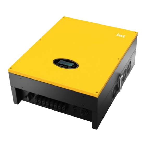
Product overview 2.2 Products appearance Figure 2.3 Products appearance of 12~17kW Figure 2.4 Products appearance of 20~40kW... - Page 15 Product overview Table 2-1 Parts instruction of three-phase grid-tied solar inverter Name Instruction Cover Operational panel LED indicators, LCD screen and buttons On –off of the DC input DC switch DC input port For the connection of solar modules...
-
Page 16: Name Plate
Product overview 2.3 Name plate Figure 2.5 shows the inverter nameplate. Figure 2.5 Name plate (1)Trademark and product type (2)Model and important technical parameters (3)Certification system of the inverter confirming (4)Serial number, company name and country of origin... -
Page 17: Models
CE certification mark. The inverter complies with the CE directive. CQC certification mark. The inverter is certified by CQC. EU WEEE mark. Cannot dispose of the inverter as household waste. 2.4 Models Table 2-2 Models of iMars grid-tied solar inverter Product name Model Rated output power (W) -
Page 18: Dimensions And Weight
Product overview 2.5 Dimensions and weight Figure 2.6 Inverter dimensions Table 2-4 Inverter dimension and net weight Net weight Model (mm) (mm) (mm) (kg) 12kW / 15kW/ 17kW / 20kW-M 20kW / 25kW / 30kW / 33kW / 35kW / 40kW Figure 2.7 Paper packages dimension... -
Page 19: Storage
Storage 3 Storage If the inverter is not put into use immediately, the storage of inverter should meet the following requirements: Do not remove the outer packing. The inverter needs to be stored in a clean and dry place, and prevent the erosion of dust and water vapor. -
Page 20: Installation
Installation 4 Installation This chapter describes how to install the inverter and connect it to the grid-tied solar system (including the connection between solar modules, public grid and inverter). Read this chapter carefully and ensure all installation requirements are met before installation. -
Page 21: Unpacking Inspection
Installation 4.1 Unpacking inspection The inverter has been thoroughly tested and rigorously checked before delivery, but damage may still occur during transportation. Before unpacking, check carefully whether the product information in the order is consistent with that on the nameplate of the package box and whether the product package is intact. - Page 22 Installation Table 4-1 Detailed delivery list of 12kW / 15kW / 17kW / 20kW-M inverter Name Quantity 6kW / 8kW / 10kW / 12kW / 15kW / 17kW / 20kW-M inverter Installation bracket Location hole template...
-
Page 23: Before Installation
Installation Name Quantity 20kW / 25kW / 30kW / 33kW / 35kW / 40kW inverter Installation bracket Location hole template operation manual Communication connector 6pairs /8 pairs DC connector (35kW/40kW) Expansion bolts M8*60 Hex combination bolt M8*20... - Page 24 Installation Figure 4.3 Optimal mounting height (2) The installation site must be well ventilated and away from raindrops or direct sunlight. (3) There must be enough pre-reserved space around the installation site for convenient installation and disassembly of the inverter and air convection, as shown in Fig 4.4.
- Page 25 Installation Figure 4.5 Side-by-side installation space requirements (4) The ambient temperature of installation should be -25° C~60° C (5) The installation site should be away from electronic devices which can generate strong electromagnetic interference (6) The inverter should be installed on firm and solid surface eg wall surface and metal bracket (7) The installation surface should be vertical to the horizontal line, as shown in Figure 4.6...
-
Page 26: Connection Cables
Installation (8) The installation should ensure that the inverter is reliably grounded, and the material of grounded metal conductor should be consistent with the metal material reserved for the grounding of the inverter. Do not remove any part and component of the inverter unintended; otherwise damage to the device and physical injury may occur. -
Page 27: Mechanical Installation
Installation 4.3 Mechanical installation The material for fixing the inverter and the installation mode vary with the different installation sites. It is recommended to install the inverter vertically to the firm wall or metal bracket. Here we take wall installation as an example to introduce the installation matters of the inverter. - Page 28 Installation (2) Drill 6 installation holes on the wall with electric drill. As shown in Figure 4.9. Figure 4.9 Drilling (3) Fix the expansion bolts to the 6 installation holes with hammer, as shown in Figure 4.10.
- Page 29 Installation Figure 4.12 Installation of inverter (6) Ensure the inverter is installed properly and tighten the M6X16 bolts into the screw holes on the left and right side of inverter(tightening torque is 4N•m). As shown in Figure 4.13.
-
Page 30: Electrical Installation
Installation 4.4 Electrical installation This section presents the detailed contents and safety precautions related to electrical connection. Fig 4.14 is the connection diagram for PV grid-connected system. Figure 4.14 Block diagram of the grid-tied solar system ... -
Page 31: Connection Of Solar Modules
Installation 4.4.1 Connection of solar modules Figure 4.15 Connection between DC connector and solar modules Connection steps: (1) Lighting, short-circuit and other protection measures which meet the local electrical safety laws and regulations are needed before the AC connection;... -
Page 32: Ac Connection Of Inverter
Installation Figure 4.16 DC input voltage measuring The PV string connected to iMars series inverter must adopt the DC connector configured especially for the inverter, do not use other connection devices without authorization from our company, otherwise damage to the device, unstable operation or fire may occur and our company will not undertake quality assurance or assume any direct or joint liability thereof. - Page 33 Installation The steps to access the grid are as follows: (1)Lighting, short-circuit and other protection measures which meet the local electrical safety laws and regulations are needed before the AC connection. Only qualified cables under the local electrical safety laws and regulations and comply with the technical parameters of this manual are allowed to connect to the inverter.
- Page 34 Installation Figure 4.19 Pull out the rail (5) Crimp the five wires(L1、 L2、 L3、 N、 PE) of the three-phase utility grid and the OT terminals firmly to ensure that the conductor of the wire is not exposed, as shown in Figure 4.20;...
- Page 35 Installation Figure 4.22 Fix the waterproof cover of junction box...
-
Page 36: Operation
Operation 5 Operation This chapter describes detailed operation of the inverter which involves the inspection before operation, grid-tied operation, stopping and daily maintenance of the inverter. -
Page 37: Inspection Before Operation
Operation 5.1 Inspection before operation Check as follows before operation (including but not limited to): (1) Ensure the installation site meet the requirement mentioned in section 4.2.2 for easy installation, removing, operation and maintenance; (2) Ensure the mechanical installation meet the requirement mentioned in section 4.3;... -
Page 38: Stopping
5.4 Daily maintenance In solar PV grid-connected power generation system, iMars series grid-connected inverter can realize grid-connected power generation and stop/start operations automatically day and light in whatever seasons. In order to safeguard and prolong the service life of the inverter, it is necessary to carry out daily maintenance and inspection on the inverter besides using the inverter str ictly according to this manual. -
Page 39: Maintenance Guide
Operation Maintenance Maintenance Maintenance methods contents cycle Check the fans of three-phase inverter to make sure out of wind is normal, the sound is normal, the fan blades are no cracks, power lines and Maintenance and control signal lines are not damaged. - Page 40 Operation Figure 5.1 Remove the cooling chamber Figure 5.2 Remove the fan mounting plate (5) Use soft brush or vacuum cleaner to clean the cooling chamber and the fans. (6) Assembly the cooling chamber or fan mounting plate into inverter.
- Page 41 Operation Fan replacement procedure is as follows: (1) Disconnect AC breaker. (2) Turn the DC switch to “OFF” position. (3) Wait for at least 10 minutes. (4) Disconnect all the electrical wirings at the bottom of the inverter.
-
Page 42: Display Panel
Display panel 6 Display panel This chapter describes the panel displaying and how to operate on the panel, which involves the LCD display, LED indicators and operation panel. -
Page 43: Led Indicators
Display panel The operation state and parameters can be attained from the LED indicators and LCD display. The displayed content and parameters can also be set or modified by the operation panel. LCD screen V - p v 1 : 0 0 0 . 0 V I - p v 1 : 0 0 0 . -
Page 44: Operation Panel
Display panel Inverter state LED indicators Description (1) Grid-tied power generation, but clock fault (A007); (2) Grid-tied power generation, but DC input fault (A001 or E001); Warn (3) Grid-tied power generation,but fan fault(E006 or Fault E012);... -
Page 45: Functions Operation
Display panel communication address, password and factory defaults. Curve Graphic Text Parameter Display Area Display Area Status Area Fault Code Menu Figure 6.2 Main interface The main interface of the LCD screen is shown as the figure above: (1) The curve displays the power changing at the current day;... - Page 46 Display panel Table 6-2 Monitoring parameters 12kW / 15kW / 20kW/ 25kW / 30kW / Monitoring content 17kW /20kW-M 33kW / 35kW / 40kW ● ● Total power produced this day(E-tod) ● ● Total power saved this day($-tod) ●...
-
Page 47: History
Display panel 6.4.2 History Press “ ” and “ ” in the main interface to select “History”, and then press “ENT” to view the parameters which is shown in figure 6.5. H i s t o r y... - Page 48 Display panel LCD menus: V - pv 1 : 000 . 0 V Setup Menu I - pv 1 : 000 . 0 A Address Date / Time V - pv 2 : 000 . 0 V...
- Page 49 Display panel Control Menu System Information Part No . Cert . Area On / Off Factory Clear Serial No . Run Param Soft Ver Restart On / Off Ctrl Part No . iMars BG 5 KTL : Sure ?...
- Page 50 Display panel Setting item LCD display Instruction Enter into the interface and edit the currency type and cash through “ ” or “ ”. And then press “ENT” again to the S e t u p C a s h...
- Page 51 Display panel Setting item LCD display Instruction Input password 0000 The password is needed when enter into the interface of “Set power”. Get the set power P-Lmt password from the supplier if necessary. Mode There are 3 submenus: ①P-Lmt Mode: LmtPower P.Factor...
- Page 52 Display panel Setting item LCD display Instruction Input password 0000 Run Param UV Volt OV time UV time UF Freq OV Volt UF time ACUV Volt(phase volt) 184V Password is required when enter into the interface of “Run Param”. Get the ACUV Time password from the supplier if necessary.
- Page 53 Display panel Setting item LCD display Instruction Input Password 0000 Run Param UV volt 1 OV time 1 UV time 1 UF Freq 1 OV volt 1 UF time 1 ACUV Volt(phase volt) 115V ACUV Time 00.04s...
-
Page 54: System Information
Display panel 6.4.5 System Information Press “ ” and “ ” in the main interface to select “System Information”, and then press “ENT” to view the parameters which is shown in figure 6.8. System Information Part No . -
Page 55: Mode Settings
Display panel Table 6-5 Inverter control Control item LCD display Instruction Control the “On/Off” through the panel. O n / O f f C t r l Press “ ” and “ ” in the control On/Off control interface to select the operation. - Page 56 Display panel S O L A R I N V E R T E R I n i t i a l i n g … … W a i t i n g > > > > > > >...
- Page 57 Display panel Country Certification Three-phase voltage Grid frequency G83-2/G59-3 415V 50Hz Australia AS4777.2&AS4777.3 Singapore 400~415V 50Hz AS/NZS3100 New Zealand Belgium Luxembourg C10/C11 380~400V 50Hz Holland Denmark TF3.2.1 380~400V 50Hz Thailand 380V 50Hz China CGC/CF001 380V 50Hz...
-
Page 58: Monitoring Communication
Monitoring communication 7 Monitoring communication This chapter describes the communication connection of inverter and monitoring system (Industrial master, private computers, smart phones and so on). -
Page 59: Standard Communication
Monitoring communication 7.1 Standard communication The standard communication mode of iMars grid-tied solar inverter is RS485 which includes “RS485” and “EXT” ports. The two ports can both communicate with private computers, smart phones and so on. The system monitoring solution are shown as figure 7.1. -
Page 60: Optional Communication
(2) According to Table 7-1, connect the communication connector pinout and the user's device, make sure the connection is correct. Figure 7.4 Communication cable connection (3) Please download the monitoring software “iMars WinExpert” and its operation instruction on website. 7.2 Optional communication The optional communication modes include Ethernet, WiFi, GPRS and ENET,which also need... - Page 61 Monitoring communication Table 7-2 Optional communication accessories Optional accessories Inverter port Port of upper PC Ethernet convert RS485-M RJ45 pin WiFi converter RS485-M WiFi signal GPRS converter RS485-M GPRS signal ENET converter RS485-M Ethernet port Please download the connection instruction, operation manual and commissioning tools on website.
-
Page 62: Troubleshooting
Troubleshooting iMars grid-tied solar inverters 8 Troubleshooting This chapter describes the fault alarm and fault code for quick troubleshooting. - Page 63 Troubleshooting iMars grid-tied solar inverters Table 8-1 Fault code Fault Message Instruction Fault analysis code PV1 undervoltage A001 Input UV Input undervoltage PV2 undervoltage A002 Bus UV Bus undervoltage DC input A003 Grid UV AC undervoltage Low voltage of the public grid...
- Page 64 Troubleshooting iMars grid-tied solar inverters Fault Message Instruction Fault analysis code E015 OutputShort Output short-circuit Output short-circuit E018 Input OC Input overcurrent DC input overcurrent Data consistency Inconsistent grid voltage, frequency, E019 Incnst fault leakage current or AC/DC injection E020...
- Page 65 Troubleshooting iMars grid-tied solar inverters If any problem, please contact with the supplier and provide following information: Model of the inverter: Serial No. of the inverter: System version:——version 1: ——version 2: ——MCU software version: Fault code:...
-
Page 66: Contact Us
Contact us iMars grid-tied solar inverters 9 Contact us Shenzhen· China INVT Solar Technology (Shenzhen) Co., Ltd. Address: Room 504, No. 7 Building, Gaofa Scientific Industrial Park, Longjing, Nanshan District, Shenzhen, China Service hotline: +86 400 700 9997 E-mail: solar-service@invt.com.cn INVT group website: www.invt.com... -
Page 67: Technical Parameters
Technical parameters iMars grid-tied solar inverters 10 Technical parameters Table 10-1Technical parameters Three-phase Model BG12KTR BG15KTR BG17KTR BG20KTR-M BG20KTR Max. DC voltage (V) 1000 1000 1000 1000 1000 Starting voltage (V) MPPT voltage range(V) 180 - 800 180 - 800... - Page 68 Technical parameters iMars grid-tied solar inverters Three-phase Model BG25KTR BG30KTR BG33KTR BG35KTR BG40KTR Max. DC voltage (V) 1000 1000 1000 1000 1000 Starting voltage (V) MPPT voltage range(V) 280-800 280-800 280-800 280-800 280-800 Rated DC input voltage range(V) 480-800 480-800...
Need help?
Do you have a question about the iMars and is the answer not in the manual?
Questions and answers