Table of Contents
Advertisement
Advertisement
Table of Contents

Subscribe to Our Youtube Channel
Related Manuals for INVT CHV180-004G-4


Summary of Contents for INVT CHV180-004G-4
- Page 1 CHV180 Series Special Inverter for Elevators...
-
Page 2: Table Of Contents
CHV180 series frequency inverter special for elevator Content Content Content ..........................1 Safety precautions ......................3 1. General ..........................4 1.1 General technical specifications ................4 1.2 Description of name plate ..................5 1.3 Selection guide...................... 5 1.4 Parts description ....................6 1.5 Description of extension card ................ - Page 3 CHV180 series frequency inverter special for elevator Content 6.14 Pd Group –Factory Setting ................79 7. Extension card ......................80 7.1 Description of communication card ..............80 7.2 Description of I/O extension card ............... 81 7.3 Description of asynchronous motor PG card ............. 83 7.4 Description of PG card for synchronous motor ..........
-
Page 4: Safety Precautions
CHV180 series frequency inverter special for elevator Safety precautions Safety precautions Please read this operational manual carefully before installation, operation, maintenance or inspection. The precautions related to safe operation are classified into “WARNING” and “CAUTION”. Points out potential danger which, if not avoided, may WARNING cause physical injury or death. -
Page 5: General
CHV180 series frequency inverter special for elevator General 1. General 1.1 General technical specifications ● Input & output Input voltage range: 400V±15% Input frequency range: 47~63Hz Output voltage range: 0~rated input voltage Output frequency range: 0~400Hz ●... -
Page 6: Description Of Name Plate
CHV180 series frequency inverter special for elevator General Elevator control logic: Internal contracting brake, contactor control. Pre-torque compensation at starting moment without weighing sensor. (only for the SIN / COS encoder) Pre-torque compensation at starting moment with weighing sensor ... -
Page 7: Parts Description
CHV180 series frequency inverter special for elevator General Rated power Rated input Rated output Model No. Size (kW) current (A) current (A) CHV180-004G-4 10.0 CHV180-5R5G-4 15.0 13.0 CHV180-7R5G-4 20.0 17.0 CHV180-011G-4 11.0 26.0 25.0 CHV180-015G-4 15.0 35.0 32.0 CHV180-018G-4 18.5 38.0... -
Page 8: Description Of Extension Card
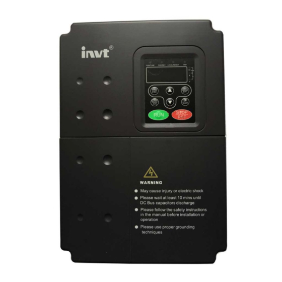
CHV180 series frequency inverter special for elevator General Keypad bracket Cover the fixed hook mouth Shield plate Operating keypad Control board Functional card Control terminal Main circuit terminal PG card expansion Control cable inlet Installation hole Figure 1.4 Parts of inverters (18.5kW and above) 1.5 Description of extension card Following extension cards can be installed in CHV180 series inverters: Extension... - Page 9 CHV180 series frequency inverter special for elevator General Extension Description Card 3. Offer frequency division output, the frequency division factor can be selected by dial switch. SIN/COS PG Receive high-speed pulse from encoder to realize high- accuracy Card close-loop vector control. (synchronous SIN/COS PG Card compatible with SIN/COS encoder.
-
Page 10: Unpacking Inspection
CHV180 series frequency inverter special for elevator Unpacking inspection 2. Unpacking inspection ! CAUTION ●Don’t install or use any inverter that is damaged or has fault parts, otherwise physical injury may occur Check the following items after unpacking the inverter: 1.... -
Page 11: Disassembly And Installation
CHV180 series frequency inverter special for elevator Disassembly and installation 3. Disassembly and installation WARNING ●Only qualified electricians are allowed to operate on the drive device/system. Ignoring the instructions in “warning” may cause serious physical injury or death or property loss. ●Connect the input power lines tightly and permanently. -
Page 12: Environmental Requirement
CHV180 series frequency inverter special for elevator Disassembly and installation 3.1 Environmental requirement 3.1.1 Temperature and Humidity The ambient temperature is among-10 °C to 40 °C and the inverter has to derate by 4% for every additional 1 °C if the ambient temperature exceeds 40 °C. The temperature cap is 50 °C. -
Page 13: Wiring
CHV180 series frequency inverter special for elevator Wiring 4. Wiring WARNING Only qualified electricians are allowed to operate on the drive for the insurance of a safe running of the inverter. Never carry out any insulation or voltage withstand tests on the cables connecting with the inverter. -
Page 14: Connections Of Peripheral Devices
CHV180 series frequency inverter special for elevator Wiring 4.1 Connections of peripheral devices Figure 4.1 Connections of peripheral devices. 4.2 Terminal configuration 4.2.1 Main circuit terminals (400VAC) POWER MOTOR Figure 4.2 Main circuit terminals (4~5.5kW) (+) PB POWER MOTOR Figure 4.3 Main circuit terminals (7.5~15kW). - Page 15 CHV180 series frequency inverter special for elevator Wiring POWER MOTOR Figure 4.4 Main circuit terminals (18.5~30kW). Functions instruction: Terminal Description R, S and T Terminals of 3 phase AC input (+) and (-) Spare terminals of external braking unit (+) and PB Spare terminals of external braking resistor P1 and (+) Spare terminals of external DC reactor...
-
Page 16: Typical Wiring Diagram
CHV180 series frequency inverter special for elevator Wiring 4.3 Typical wiring diagram Figure4. 6 Wiring diagram. 4.4 Wiring the main circuits 4.4.1 Wiring at the side of power supply ●4.4.1.1 Circuit breaker It is necessary to connect a circuit breaker which is compatible with the capacity of inverter between 3ph AC power supply and power input terminals (R, S and T). - Page 17 CHV180 series frequency inverter special for elevator Wiring capacity of breaker is 1.5~2 times to the rated current of inverter. Please refer to the chapter of Specifications of Breaker, Cable, and Contactor for details. ●4.4.1.2 Contactor In order to cut off the input power effectively when something is wrong in the system, contactor should be installed at the input side to control the ON-OFF of the main circuit power supply.
- Page 18 CHV180 series frequency inverter special for elevator Wiring installed at (+) and PB terminals. The wire length of braking resistor should be less than • Inverters of 18.5kW and above need connect external braking unit which should be installed at (+) and (-) terminals. The cable between inverter and braking unit should be less than 5m.
-
Page 19: Wiring Control Circuit Terminals
CHV180 series frequency inverter special for elevator Wiring Grid Figure 4.9 Wiring of regenerative unit. 4.4.5 Ground wiring (PE) Ground the PE terminal of the inverter with grounding resistors (less than 10 ) for the insurance of safety and avoidance of electrical shock and fire. It is apporiate to use thick and short multiple copper core wires whose sectional area is larger than 3.5m ㎡. - Page 20 CHV180 series frequency inverter special for elevator Wiring Terminal Description terminal as default setting. If user need external power supply, disconnect +24V terminal with PW terminal and connect PW terminal with external power supply. Provide output power supply of +24V. +24V Maximum output current: 150mA Common ground terminal for digital signal and +24V (or external...
-
Page 21: Installation Guidline To Emc Compliance
CHV180 series frequency inverter special for elevator Wiring Terminal Description J2, J4, J5, J13 They are prohibited to be changed, otherwise it will cause and J14 inverter malfunction. Switch between (0~10V) voltage input and (0~20mA) current input. V connect to GND means voltage input; I connect to GND means current input. - Page 22 CHV180 series frequency inverter special for elevator Wiring smooth working in certain electromagnetic environment. The following is its EMC features: Input current is non-sine wave. The input current includes large amount of high-harmonic waves that can cause electromagnetic interference, decrease the grid power factor and increase the line loss.
- Page 23 CHV180 series frequency inverter special for elevator Wiring Device categorization: there are different electric devices contained in one control cabinet, such as inverter, filter, PLC and instrument etc, which have different ability of emitting and withstanding electromagnetic noise. Therefore, it needs to categorize these devices into strong noise device and noise sensitive device.
- Page 24 CHV180 series frequency inverter special for elevator Wiring the longer of the motor cable and/or the bigger cable section area, the larger leakage current will occur. Countermeasure: Decreasing the carrier frequency can effectively decrease the leakage current. In the case of motor cable is relatively long (longer than 50m), it is necessary to install AC reactor or sinusoidal wave filter at the output side, and when it is even longer, it is necessary to install one reactor at every certain distance.
-
Page 25: Operation
CHV180 series frequency inverter special for elevator Operation 5. Operation 5.1 Operating keypad description 5.1.1 Keypad schematic diagram Figure 5.1 Keypad schematic diagram. 5.1.2 Button function description Button Name Description Programming Entry or escape of first-level menu. Enter Key Progressively enter menu and confirm parameters. UP Increment Progressively increase data or function codes. - Page 26 CHV180 series frequency inverter special for elevator Operation Button Name Description In running state, restricted by P7.04, can be used to STOP/RESET stop the inverter. When fault alarm, can be used to reset the inverter without any restriction. Determined by Function Code P7.03: 0: Jog operation 1: Switch between forward and reverse 2: Clear the UP/DOWN settings.
-
Page 27: Operation Process
CHV180 series frequency inverter special for elevator Operation 5.1.3.2 Unit indicator light description Unit indicator Description Frequency unit Current unit Voltage unit Rotating speed unit Percentage Hz+V 5.1.3.3 Digital display Have 5 digit LED , which can display all kinds of monitoring data and alarm codes such as reference frequency, output frequency and so on. - Page 28 CHV180 series frequency inverter special for elevator Operation Stand-by/operation 50.00 0.000 >> SHIFT 0.000 DATA DATA 1.000 P1.00 DATA P1.02 P1.01 Figure 5.2 Flow chart of parameter setting. Under the third-class menu, if the parameter has no flickering bit, it means the function code cannot be modified.
-
Page 29: Running State
CHV180 series frequency inverter special for elevator Operation to the description of Function Code P0.08. And then press RUN on the keypad panel, the inverter will automatically calculate parameters of the motor. Then motor autotuning is finished. In the self-learning process, use >>/ SHIFT can change parameters and monitor running state of inverter. - Page 30 CHV180 series frequency inverter special for elevator Operation 5.3.3 Operation In running state, there are twenty one running parameters which can be chosen to display or not. They are: running frequency, reference frequency, DC bus voltage, output voltage, output current, rotating speed, output power, output torque, PID setting, PID feedback, ON-OFF input state, open collector output state, length value, count value, step number of PLC or multi-step speed, AI1 voltage, AI2 voltage, AI3 voltage/current, AI4 voltage, HDI1 frequency, HDI2 frequency.
-
Page 31: Detailed Function Description
CHV180 series frequency inverter special for elevator Detailed function description 6. Detailed function description 6.1 P0 Group--Basic function Function Setting Factory Name Description Code Range Setting 0: Sensorless vector control Speed control P0.00 1: Vector control With PG mode 2: V/F control 0: Sensorless vector control: It is widely used in the application such as low-grade elevator which requires lower accuracy or used for debugging. - Page 32 CHV180 series frequency inverter special for elevator Detailed function description 2: Communication ( LED lights on) “LOCAL/REMOT” The operation of inverter can be controlled by host through communication. If select “Communication”, the user should select the serial communication extension card which matches with CHV180 serials inverter.
- Page 33 CHV180 series frequency inverter special for elevator Detailed function description input and current input is controlled by the jumper wire J18. Note: 100% of AI is corresponding to the rated speed of the elevator. 3: Multi-step speed The reference frequency is determined by P1 group and P5 group. The selection of steps is determined by combination of multi-step speed terminals.
- Page 34 CHV180 series frequency inverter special for elevator Detailed function description Function Setting Factory Name Description Code Range Setting Keypad P0.05 reference 0.00 ~ P0.02 1.500m/s 1.500m/s speed When P0.03 is set to be 0, this parameter is the reference speed of the inverter. Function Setting Factory...
- Page 35 CHV180 series frequency inverter special for elevator Detailed function description Carrier frequency Factory Model Setting( kHz ) 4kW~11kW 15kW~30kW The advantage of high carrier frequency: ideal current waveform, little current harmonic wave and motor noise. The disadvantage of high carrier frequency: increasing the switch loss, increasing inverter temperature and the impact to the output capacity.
- Page 36 CHV180 series frequency inverter special for elevator Detailed function description and return to the stop state. e. During the autotuning, press the >>/SHIFT, it can switch keypad to display parameters, and monitor the running state. Press the STOP/RST,it will stop the autotuning. P0.01=0(Keypad control) Synchronous Asynchronous...
-
Page 37: P1 Group--Speed Curve
CHV180 series frequency inverter special for elevator Detailed function description leakage inductance of motor can be detected and the mutual inductance and current without load will not be detected by static autotuning.If needed, user should input suitable value according to experience. For synchronous motor, the self-learning current (P4.10) is set to get the magnetic pole initial position (P4.03). - Page 38 CHV180 series frequency inverter special for elevator Detailed function description Function Setting Factory Name Description Code Range Setting Multi-step P1.03 0.000~P0.02 0.000~P0.02 0.000m/s speed 3 Multi-step P1.04 0.000~P0.02 0.000~P0.02 0.000m/s speed 4 Multi-step P1.05 0.000~P0.02 0.000~P0.02 0.000m/s speed 5 Multi-step P1.06 0.000~P0.02 0.000~P0.02 0.000m/s...
- Page 39 CHV180 series frequency inverter special for elevator Detailed function description Function Setting Factory Name Description Code Range Setting P1.11 Deceleration 0.001~10.000 0.001~10.000 0.700m/s P Stop quadric P1.12 0.001~10.000 0.001~10.000 0.350m/s P deceleration Stop P1.13 0.001~10.000 0.001~10.000 0.700m/s P deceleration P1.14 Start speed 0.000~0.250 0.000~0.250...
- Page 40 CHV180 series frequency inverter special for elevator Detailed function description P1.14 is the initial speed when the inverter starts. If the setting speed is less than start speed, the output frequency is 0 when running. Only when the setting speed is greater than or equal to start speed, the inverter will start with start speed, and run according to S-curve.
- Page 41 CHV180 series frequency inverter special for elevator Detailed function description Function Setting Factory Name Description Code Range Setting Motor 0.600 P1.19 autotuning 0.001~10.000 0.001~10.000 acceleration Motor P1.20 autotuning 0.001~10.000 0.001~10.000 0.600m/s deceleration These parameters are used to set acceleration and deceleration of motor’s parameter autotuning.
- Page 42 CHV180 series frequency inverter special for elevator Detailed function description P1.21 P1.22 P1.22 FWD/REV EMER Figure 6.7 The emergency running curve. Please refer to chapter A.2.4 for detailed emergency running. Note: if use the function of emergency running, need shield the inverter protection function of input open-phase (P9.00=0).
- Page 43 CHV180 series frequency inverter special for elevator Detailed function description Function Setting Factory Name Description Code Range Setting detection The above function codes will be valid after the forced deceleration switch input is selected, the effect of forced deceleration is to prevent elevator from top-hitting or bottom-clashing in the process of up or down running.
-
Page 44: P2 Group--Motor Parameters
CHV180 series frequency inverter special for elevator Detailed function description Feedback terminals signal of forced deceleration switch action is effective. During run-up process, it comes across up-forcing switch, or during run-down process, it comes across down-forcing switch. Current running speed is greater than the detected speed of corresponding forced deceleration switch, if not;... - Page 45 CHV180 series frequency inverter special for elevator Detailed function description Function Setting Factory Name Description Code Range Setting Wheel diameter P2.01 of traction 100~2000 100~2000 500mm motor P2.02 Reduction ratio 1.00~100.00 1.00~100.00 30.00 Hoist rope P2.03 hanging ratio P2.01, P2.02 and P2.03 are parameters of the elevator traction motor, only when parameters are set correctly, the inverter running-speed can be right parallelism with elevator’s factual speed.
-
Page 46: P3 Group--Vector Control
CHV180 series frequency inverter special for elevator Detailed function description Function Setting Factory Name Description Code Range Setting Motor stator Depend P2.10 0.001~65.535Ω 0.001~65.535 resistor on model Motor rotor Depend P2.11 0.001~65.535Ω 0.001~65.535 resistor on model Stator and Depend P2.12 rotor 0.1~6553.5mH 0.1~6553.5... - Page 47 CHV180 series frequency inverter special for elevator Detailed function description Function Setting Factory Name Description Code Range Setting Switch low P3.03 point 0.00Hz~P3.07 0.00~P3.07 5.00Hz frequency ASR high speed P3.04 0~100 0~100 proportion gain ASR high P3.05 speed integral 1.00s 0.01~10.00s 0.01~10.00s time...
- Page 48 CHV180 series frequency inverter special for elevator Detailed function description steady-state-oscillation, and maybe the speed static will occur. Speed loop parameter PI has strong relationship with the system’s inertia, in order to meet the requirement of any situation; the PI should be adjusted based on the default set when the load of the system changed.
-
Page 49: P4 Group -- Encoder Parameter
CHV180 series frequency inverter special for elevator Detailed function description Function Setting Factory Name Description Code Range Setting limit 100.0% corresponds with the rated current of inverter. Function Setting Factory Name Description Code Range Setting P3.13 Reserved 0~65536 0~65536 P3.14 Reserved 0~65536 0~65536... - Page 50 CHV180 series frequency inverter special for elevator Detailed function description when P4.02 is changed. Function Setting Factory Name Description Code Range Setting Magnetic pole P4.03 0.00~360.00 0.00~360.00 0.00 initial position Magnetic pole initial position will be updated automatically after autotunning of synchronous motor, the parameter shouldn’t be modified.
-
Page 51: P5 Group--Input Terminals
CHV180 series frequency inverter special for elevator Detailed function description Function Setting Factory Name Description Code Range Setting Magnetic pole P4.07 position 0.50~1.50 0.50~1.50 1.00 amplitude gain C phase P4.08 magnetic pole 0~1024 0~1024 position offset D phase pole P4.09 0~1024 0~1024 position offset... - Page 52 CHV180 series frequency inverter special for elevator Detailed function description Function Setting Factory Name Description Code Range Setting Terminal input P5.00 0~0x3FF 0~0x3FF mode selection The function is to select the switch signal input terminals to be natural open or natural close.
- Page 53 CHV180 series frequency inverter special for elevator Detailed function description Function Setting Factory Name Description Code Range Setting function terminal S7 Terminal Programmable multifunction P5.08 0~40 function terminal S8 Terminal Programmable multifunction P5.09 0~40 function terminal S9 Terminal Programmable multifunction P5.10 0~40 function...
- Page 54 CHV180 series frequency inverter special for elevator Detailed function description Multi-step speed 3 Multi- step speed 2 Multi- step speed 1 BIT2 BIT1 BIT0 11~13:Up forced deceleration 1~3 Up forced signal is use for preventing the elevator crash to the top. Please refer to P1.23 ~ P1.28 for the description of specific function.
- Page 55 CHV180 series frequency inverter special for elevator Detailed function description Function Setting Factory Name Description Code Range Setting P5.13 AI1 lower limit 0.00V~10.00V 0.00~10.00 0.00V AI1 lower limit P5.14 corresponding -100.0%~100.0% -100.0~100.0 0.0% setting P5.15 AI1 upper limit 0.00V~10.00V 0.00~10.00 10.00V AI1 upper limit P5.16...
-
Page 56: P6 Group -- Output Terminals
CHV180 series frequency inverter special for elevator Detailed function description Function Setting Factory Name Description Code Range Setting P5.18 AI2 lower limit 0.00V~10.00V 0.00~10.00 0.00V AI2 lower limit P5.19 corresponding -100.0%~100.0% -100.0~100.0 0.0% setting P5.20 AI2 upper limit 0.00V~10.00V 0.00~10.00 5.00V AI2 upper limit P5.21... - Page 57 CHV180 series frequency inverter special for elevator Detailed function description Function Setting Factory Name Description Code Range Setting Y1 output P6.01 Open-collector output 0~20 selection Y2 output P6.02 Open-collector output 0~20 selection HDO open collector P6.03 Open-collector output 0~20 output selection Relay 1 output P6.04...
- Page 58 CHV180 series frequency inverter special for elevator Detailed function description Setting Function Description Value Frequency Please refer to the description of P6.24. reached FDT reached Please refer to the description of P6.22 and P6.23. Elevator running ON: From brake-releasing delay finished to closing 1 (LR1) brake finished.
- Page 59 CHV180 series frequency inverter special for elevator Detailed function description Setting Value Function Range Output torque 0~2*rated rated current AI1 input 0~10V AI2 input 0~10V/0~20mA 9~14 Reserved Reserved Function Setting Factory Name Description Code Range Setting AO1 lower P6.10 0.0%~P6.12 0.0~ P6.12 0.0% limit...
- Page 60 CHV180 series frequency inverter special for elevator Detailed function description Function Setting Factory Name Description Code Range Setting limit corresponding output HDO upper P6.20 0.0%~100.0% P6.18~100.0 100.0% limit HDO upper limit P6.21 0.0 ~ 50.0kHz 0.0~50.0 50.0kHz corresponding output The corresponding relationship of A02 output is similar to that of AO1. High speed pulse output is illustrated as below: Figure 6.13 Relationship between HDO and corresponding setting.
- Page 61 CHV180 series frequency inverter special for elevator Detailed function description Figure 6.14 FDT Level diagram. Function Setting Factory Name Description Code Range Setting Frequency arrival P6.24 0.00~100.0% 0.00~100.0 0.0% detecting range When output frequency reaches reference frequency, it can adjust the detection amplitude.
-
Page 62: P7 Group -Human-Machine Interface
CHV180 series frequency inverter special for elevator Detailed function description Function Setting Factory Name Description Code Range Setting P6.26 0~65536 0~65536 6.8 P7 Group –Human-Machine interface Function Setting Factory Name Description Code Range Setting User P7.00 0~65535 0~65535 password The password protection function will be valid when it is set to be any nonzero data. When P7.00 is set to be 00000, the user’s password set before will be cleared and the password protection function will be disabled. - Page 63 CHV180 series frequency inverter special for elevator Detailed function description 0: Examine running 1: FWD/REV switching Function Setting Factory Name Description Code Range Setting 0: Valid only when keypad control (P0.01=0) 1: Valid when keypad or terminal STOP/RST control (P0.01=0 or 1) P7.04 function 2: Valid when keypad or...
- Page 64 CHV180 series frequency inverter special for elevator Detailed function description Function Setting Factory Name Description Code Range Setting Running state P7.06 display 0x00FF 0~0x03FF 0x00FF selection In the running state, CHV180 series inverters can display 5 parameters: running speed, set speed, bus voltage, output voltage and output current. The displayings of other parameters are determined by the function code.
- Page 65 CHV180 series frequency inverter special for elevator Detailed function description BIT7 BIT6 BIT5 BIT4 BIT3 BIT2 BIT1 BIT0 Output Input Referenc Motor DC bus Reference terminal terminal poles voltage speed state state frequency BIT15 BIT14 BIT13 BIT12 BIT11 BIT10 BIT9 BIT8 Pole Reserved Reserved Reserved Reserved Reserved Reserved Reserved...
- Page 66 CHV180 series frequency inverter special for elevator Detailed function description Function Setting Factory Name Description Code Range Setting Previous two P7.13 0~31 0~31 Reserved fault type Previous fault P7.14 0~31 0~31 type Current fault P7.15 0~31 0~31 type These parameters record three recent fault types. 0 means no fault, 1~31 shows different fault types.
-
Page 67: P8 Group --Enhanced Function
CHV180 series frequency inverter special for elevator Detailed function description This value can inform the state of digital input signal at fault. The state of the current fault input terminal is decimal number. Display the state of all digital input terminals at the latest fault, the sequence is: BIT5 BIT4 BIT3... - Page 68 CHV180 series frequency inverter special for elevator Detailed function description Pre-torque compensation Direction running Comparison value Car > counterpoise P8.02*(car - P8.01) Up running Car < counterpoise P8.03*( car - P8.01) Car > counterpoise P8.03*( car - P8.01) Down running Car <...
- Page 69 CHV180 series frequency inverter special for elevator Detailed function description Function Setting Factory Name Description Code Range Setting Brake P8.07 threshold 560.0~750.0V 560.0~750.0 700.0 voltage This function code is to set the threshold DC bus voltage when dynamic braking, set the parameter correctly can improve the performance of braking.
- Page 70 CHV180 series frequency inverter special for elevator Detailed function description Function Setting Factory Name Description Code Range Setting feedback inspecting interval After selecting contactor control, the fault time of elevator relay action is greater han P8.12, inverter will report contactor feedback fault (TbE). Function Setting Factory...
- Page 71 CHV180 series frequency inverter special for elevator Detailed function description Function Setting Factory Name Description Code Range Setting Stop brake P8.16 starting 0.00~P0.04 0.00~P0.04 0.00 frequency Stop brake P8.17 0.0~50.0s 0.0~50.0 waiting time Stop DC P8.18 0.0~120% 0.0~120 brake current Stop DC P8.19 0.0~50.0s...
-
Page 72: P9 Group -- Protection Parameters
CHV180 series frequency inverter special for elevator Detailed function description inhibition of motor oscillation in this mode. Function Setting Factory Name Description Code Range Setting P8.22 Reserved 0~65535 0~65535 P8.23 Reserved 0~65535 0~65535 6.10 P9 Group -- Protection parameters Function Setting Factory Name... - Page 73 CHV180 series frequency inverter special for elevator Detailed function description Function Setting Factory Name Description Code Range Setting Overload P9.04 pre-warning 20.0%~150.0% 20.0~150.0 130.0% threshold 0: Always detect relative to motor rated current 1: Detect while constant speed Overload relative to motor rated current P9.05 pre-warning 2: Always detect...
-
Page 74: Pa Group --Serial Communication
CHV180 series frequency inverter special for elevator Detailed function description following diagram: Figure 6.17 Overload pre-warning schematic diagram. Function Setting Factory Name Description Code Range Setting Threshold of P9.07 over speed 0.0%~50% 0.0~50 20.0% deviation Detection time of over P9.08 0.000~10.000s 0.000~10.000 0.5000... - Page 75 CHV180 series frequency inverter special for elevator Detailed function description to be 0 (that is the broadcast communication address), all slaves on the MODBUS bus will receive the frame, but the slaves will not make any response. Note that the slave address should not be set to be 0.
- Page 76 CHV180 series frequency inverter special for elevator Detailed function description Function Setting Factory Name Description Code Range Setting Communication PA.03 0~20ms 0~20 reponse delay Reply delay: refers to the interval time between the end of data receiving of the inverter and the reply data sending of the upper computer.
-
Page 77: Pb Group - Display Monitor
CHV180 series frequency inverter special for elevator Detailed function description Function Setting Factory Name Description Code Range Setting PA.06 Reserved 1~127 1~127 PA.07 Reserved PA.08~PA.11 Reserved 0~65535 0~65535 CAN communication is reserved. 6.12 Pb Group – Display monitor Function Setting Factory Name Description... -
Page 78: Pc Group -Load Starting Parameters
CHV180 series frequency inverter special for elevator Detailed function description Function Setting Factory Name Description Code Range Setting AD detection value of Pb.06 0~1024 encoder C phase AD detection value of Pb.07 0~1024 encoder D phase The parameters display the sampling value of present encoder signal, the function codes are used to correct zero-bias of encoder (P4.08,P4.09) when the synchronizer performs static autotuning. - Page 79 CHV180 series frequency inverter special for elevator Detailed function description P3.01. Function Setting Factory Name Description Code Range Setting Load compensation PC.03 0~100 0~100 ASR proportion gain Load compensation PC.04 0.01~10.00s 0.01~10.00s 0.04s ASR integral gain Position loop PC.05 APR proportion 0~100 0~100 gain...
-
Page 80: Pd Group -Factory Setting
CHV180 series frequency inverter special for elevator Detailed function description Function Setting Factory Name Description Code Range Setting Current command PC.08 0~65536 0~65536 1000 filter coefficient Bit0 and Bit1 are current loop filter parameters. The response of system will be decreased when they are increased, The parameter usually is adjusted with speed loop P3.02 and P3.06,If there is abnormal noise when the motor is running, the noise can be eliminated by increasing the parameter or P3.02 and P3.06.Bit2~bit5 are... -
Page 81: Extension Card
CHV180 series frequency inverter special for elevator Extension card 7. Extension card 7.1 Description of communication card 7.1.1 Model The communication card of CHV180 series inverters are PN000TXWX. The communication card provides RS232 and RS485 for users to select. 7.2 Installation RS 232 RS 485 Figure 7.1... -
Page 82: Description Of I/O Extension Card
CHV180 series frequency inverter special for elevator Extension card There are 2 groups of wiring terminals. Figure 7.3 DB9: Bus-connector wiring terminal (RS232) Figure 7.4 RS485 wiring terminal 7.1.5 Wiring precautions Please install the card when the inverter is disconnected completely. Please connect the communication card with the slot of the control board with proper techniques. - Page 83 CHV180 series frequency inverter special for elevator Extension card Terminal name Usage and instruction Input impedance:10kΩ (voltage input) / 250Ω(current input) Open collector output terminal, the corresponding common ground output terminal is CME External voltage range:0~24V Output current range:0~50mA CME2 Open collector output common terminal Analog quantity output terminal Output range:0~10V/0~20mA(select voltage or current output by...
-
Page 84: Description Of Asynchronous Motor
CHV180 series frequency inverter special for elevator Extension card Figure 7.5 Dimension of I/O extension card. (2) Sketch map of terminal compositor 7.2.3 Installation of I/O extension card for CHV180 Operation panel Control terminal CHARGE light PG Extension Main circuit terminal I/O Extension card Main circuit cable inlet Control cable inlet... - Page 85 CHV180 series frequency inverter special for elevator Extension card Terminal name Specification TERA+ Input channel of the encoder signal TERA- Voltage range: 12~15V TERB+ Response speed: 0~80kHz TERB- Output frequency: 0~80kHz TER-OA Output impedance: 30Ω TER-OB Frequency range:1~256 7.3.1.2 Dimensions and Installation of asynchronous motor PG card Outside dimensions and installation Installation diagram of PG card dimensions of PG card...
- Page 86 CHV180 series frequency inverter special for elevator Extension card 7.3.2.2 Terminals and DIP There are 9 wiring terminals in asynchronous PG card: +12V COM1 TERA+ TERA- TERB+ TERB- TER-OA TER-OB COM1 Figure 7.8 Wiring terminals in asynchronous PG card. Among them, +12V and COM1 are the power supply output for the encoder; TERA+, TERA-, TERB+ and TERB- are the input terminal for the encoder;...
- Page 87 CHV180 series frequency inverter special for elevator Extension card 7.3.2.4 Wiring precautions The signal wire of the PG card should be routed separately from the power lines. Please select the shield cables as the PG signal wire for the avoidance of encoder signal.
-
Page 88: Description Of Pg Card For Synchronous Motor
CHV180 series frequency inverter special for elevator Extension card Use shield cable Push-pull output PG Card coder COM1 +3.3V TERA TERA +3.3V TERB TERB Figure 7.11 Wiring Diagram of Push-pull Output Coder. (4) Wiring Diagram of PG Card Frequency-division Output PG Card +12V COM1... - Page 89 CHV180 series frequency inverter special for elevator Extension card Users select the card according to the actual requirement. 7.4.2 Dimensions and schematic diagram of UVW type synchronous PG Figure 7.13 Dimensions and schematic diagram of UVW type synchronous PG Note: 1) The installation position and method of synchronous motor PG card are the same as that of the asynchronous motor PG card, but the contact pin has two lines, the contact pin of asynchronous motor PG card is only one line(the below...
- Page 90 CHV180 series frequency inverter special for elevator Extension card TER-OA, TER-OB and COM1 are the signal terminals of frequency division output. Note: PE terminal in PG card are not grounded to the earth, so users can grounding it by themselves. DB15 is the port of the encoder input signal.
- Page 91 CHV180 series frequency inverter special for elevator Extension card Decimal Digit Binary Digit Frequency Division Coefficients 00000000 00000001 00000010 … … … … 11111111 .90.
-
Page 92: Trouble Shooting
CHV180 series frequency inverter special for elevator Trouble shooting 8. Trouble shooting 8.1 Fault and trouble shooting The inverter has perfect functions to carry out effect protection; meanwhile the performance of equipment can be full played. Please refer to the following table to analyze the possible fault and find out the reason for exclusion. - Page 93 CHV180 series frequency inverter special for elevator Trouble shooting 1. Check the input Over-voltage 1.Input voltage is abnormal power. when 2. After sudden power off, 2. Avoid restarting after acceleration restart the rotating motor. stopping. 1. Increase Dec time. 1. Dec time is too short. Over-voltage 2.
- Page 94 CHV180 series frequency inverter special for elevator Trouble shooting the encodering disk or run 4. Adjust the direction of at low speed for a long the encoding disk. time. Check the wiring, Input phase failure Input phase installation and power R,S,T.
- Page 95 CHV180 series frequency inverter special for elevator Trouble shooting 1. Select proper baud 1. Improper baud rate rate. setting. 2. Press STOP/RST to Communication 2. Receive wrong data. reset and ask for fault 3. Communication is support. interrupted for long time. 3.
- Page 96 CHV180 series frequency inverter special for elevator Trouble shooting 1. Inspect motor parameters. Detection fault of The autotuning detection PPCE 2. Input correct magnetic pole fault of magnetic pole. parameters of motor and re-autotuning. 1. Press STOP/RST to 1. Read/Write fault of reset.
-
Page 97: Common Faults And Solutions
CHV180 series frequency inverter special for elevator Trouble shooting 8.2 Common faults and solutions Inverter may have following faults or malfunctions during operation, please refer to the following solutions. No display after power on: Inspect whether the voltage of power supply is the same as the inverter rated voltage or not with multi-meter. -
Page 98: Maintenance
CHV180 series frequency inverter special for elevator Maintenance 9. Maintenance WARNING ● Maintenance must be performed according to designated maintenance methods. ● Only qualified technicians are allowed to carry out the maintenance. ● Disconnect the power supply before maintenance. Wait for 10 minutes before maintenance. -
Page 99: Replacement Of Wearing Parts
CHV180 series frequency inverter special for elevator Maintenance Items Instructions Method The screws of Check the screws are the external Tight the screw driver/sleeve. loose or not. terminal Use dry and compressed air to clean PCB board Dust and dirtiness. the dirtiness completely. -
Page 100: Communication Protocol
CHV180 series frequency inverter special for elevator Communication protocol 10. Communication protocol 10.1 Interfaces RS485: asynchronous, half-duplex. Default: 8-E-1, 19200bps. See Group PC parameter settings. 10.2 Communication modes (1) The protocol is Modbus protocol. Besides the common register Read/Write operation, it is supplemented with commands of parameters management. -
Page 101: Protocol Function
CHV180 series frequency inverter special for elevator Communication protocol address 1. Node addr. Command Data addr. Read No. 0x01 0x03 0x00 0x02 0x00 0x01 0x25 0xCA The table below shows the reply frame from slave node address 1. Node addr. Command Bytes No. - Page 102 CHV180 series frequency inverter special for elevator Communication protocol The data address of control and state parameters please refer to the following table. Parameter Description Address Meaning of value Feature 0001H: Up running 0002H: Down running 0003H: Up running overhaul 0004H: Down running overhaul Control command 1000H...
- Page 103 CHV180 series frequency inverter special for elevator Communication protocol Parameter Description Address Meaning of value Feature 3009H Input terminal state 300AH Output terminal state. 300BH Input of AI1 300CH Input of AI2 300DH Torque compensation 300EH Pole position 300FH ~ Reserved 3014H Torque direction...
- Page 104 CHV180 series frequency inverter special for elevator Communication protocol Protocol data unit Data length(bytes) Range Command 0x03 Returned byte number 2* Read number Content 2* Read number If the command is reading the type of inverter (data address 0x3016), the content value in reply message is the device code: The high 8 bit of device code is the type of the inverter, and the low 8 bit of device code is the sub type of inverter.
-
Page 105: Note
CHV180 series frequency inverter special for elevator Communication protocol Value Name Mean error same as the password set by P7.00. Check The CRC (RTU mode) or LRC (ASCII mode) check not error passed. It only happen in write command, the reason maybe: Written not 1. -
Page 106: Crc Check
CHV180 series frequency inverter special for elevator Communication protocol 10.6 CRC check For higher speed, CRC-16 uses tables. The following are C language source code for CRC-16. unsigned int crc_cal_value(unsigned char *data_value,unsigned char data_length) int i; unsigned int crc_value=0xffff; while(data_length--) crc_value^=*data_value++;... - Page 107 CHV180 series frequency inverter special for elevator Communication protocol Higher byte of 0004H Low byte of 0004H High byte of 0005H Low byte of 0005H Low byte of CRC High byte of CRC T1-T2-T3-T4 (transmission time of 3.5 bytes) 10.7.2 ASCII mode, read 2 data from 0004H: The request command is: START ‘:’...
- Page 108 CHV180 series frequency inverter special for elevator Communication protocol ‘1’ Higher byte of 0004H ‘3’ ‘8’ Low byte of 0004H ‘8’ ‘0’ High byte of 0005H ‘5’ ‘D’ Low byte of 0005H ‘C’ LRC CHK Lo ‘7’ LRC CHK Hi ‘C’...
- Page 109 CHV180 series frequency inverter special for elevator Communication protocol T1-T2-T3-T4 (transmission time of 3.5 bytes) 10.7.4 ASCII mode, write 5000(1388H) into address 0008H, slave node address The request command is: START ‘:’ ‘0’ Node address ‘2’ ‘0’ Command ‘6’ ‘0’ High byte of data address ‘0’...
- Page 110 CHV180 series frequency inverter special for elevator Communication protocol ‘8’ LRC CHK Hi ‘5’ LRC CHK Lo ‘9’ END Hi END Lo 10.7.5 Command code 08H (0000 1000) for diagnosis Sub-function Code Description 0000 Return to inquire information data For example: The inquiry information string is same as the response information string when the loop detection to address 01H of driver is carried out.
- Page 111 CHV180 series frequency inverter special for elevator Communication protocol ‘0’ Node address ‘1’ ‘0’ Command ‘8’ ‘0’ High byte of sub-function code ‘0’ ‘0’ Low byte of sub-function code ‘0’ ‘1’ High byte of data content ‘2’ ‘A’ Low byte of data content ‘B’...
-
Page 112: Appendix A: Commissioning Guide
CHV180 series frequency inverter special for elevator Appendix A Appendix A: Commissioning guide A.1 Runing and parameter-adjusting After setting application parameters, the parameters should be checked according to function requirement, especially the parameters that are interrelated to peripheral wiring of inverter, such as operation mode, control mode, setting of programmable input/output and selecting of feedback quantity. -
Page 113: Elevator Running Mode
CHV180 series frequency inverter special for elevator Appendix A (stopping quadric deceleration), P1.13 (stopping deceleration), P3.00 and P3.01 (PI parameter of low speed), P8.06 (contracting brake close delay time). A.1.5 Accuracy adjusting of elevator flat floor If leveling error of each floor is different, adjust each position of flashboard to keep the same errors on every floor, and adjust creeping speed of elevator (set by multi-step speed) and P1.12 (stopping quadric deceleration). - Page 114 CHV180 series frequency inverter special for elevator Appendix A Elevator operation Close out Zero run Figure A.2 Sequence chart of running for Multi-step speed control. The meanings of T1~T7 are as follows: Symbol Meanings The system delay from the time when the inverter receives running signal to the time when the inverter outputs pull-in command of contactor.
- Page 115 CHV180 series frequency inverter special for elevator Appendix A (MS1~MS3), delay the time of T1, the inverter output actuate control command to contactor。 After T2, when the inverter received the feedback signal of contactor. It is running at 0 speed, and output Y1 at the same time. After T3, the inverter output contracting brake close signal (FC).
- Page 116 CHV180 series frequency inverter special for elevator Appendix A Function Recommendation Name Remark Code setting P1.05 Multi-step Speed 5 Normal low speed P1.06 Multi-step Speed 6 Normal high speed 1 P1.07 Multi-step Speed 7 Normal high speed 2 Start quadratic P1.08 0.350m/s acceleration...
- Page 117 CHV180 series frequency inverter special for elevator Appendix A Function Recommendation Name Remark Code setting P2.06 Motor rated speed Tractor nameplate P2.07 Motor rated voltage Tractor nameplate P2.08 Motor rated current Tractor nameplate Recommendation P3 group Vector control Set by running effect setting Encoder type P4.00...
- Page 118 CHV180 series frequency inverter special for elevator Appendix A Function Recommendation Name Remark Code setting and contactor control mode Brake open delay P8.06 0.0s time Set by on-site debugging Brake feedback P8.11 check time Contactor feedback P8.12 check time Stop contracting P8.13 0.00Hz brake frequency...
- Page 119 CHV180 series frequency inverter special for elevator Appendix A The time sequence: The running time sequence is the same as Multi-step Speed’s on the whole. For detailed description, please refer to Figure A.2. Note: 1) The s-curve of inner inverter is invalid with analog quantity speed tracking running mode.The run s-curve of elevator is generated by external controller.
- Page 120 CHV180 series frequency inverter special for elevator Appendix A P1.18 P1.17 P1.16 Figure A.5 Sequence chart of overhaul running. The meanings of T1~T7 are as follows: Sign Meanings The time is the system delay time from inverter received running signal to output actuates command of contactor. The time is the wait delay time from inverter output contactor actuates command to receive contactor feedback signal.
- Page 121 CHV180 series frequency inverter special for elevator Appendix A a constant speed. After the overhaul command (EXM) is cut off, the inverter is decelerated stopping with overhaul run deceleration (P1.18). When the speed reaches P8.13, the inverter output the brake open command (FC), after T5 for cutting off running command.
- Page 122 CHV180 series frequency inverter special for elevator Appendix A P1.22 P1.22 P1.21Emergency speed EMER Figure A.7 Sequence chart of emergency run. The meanings of T0~T8 are as follows: Symbol Description The time is the delay time from the main power is off to the switch of emergency power is on The time is the delay time from the controller output emergency command to output run command...
- Page 123 CHV180 series frequency inverter special for elevator Appendix A inverter start to run at zero speed, at the same time output running signal (Y1). After T4, the inverter output brake closed signal (FC). After T5, the inverter received brake feedback signal(FB), after affirming the brake is open completely ,the inverter accelerate with emergency acceleration (P1.22) reach to emergency speed (P1.21), and then run at a constant speed.
-
Page 124: Appendix B: Dimension Of The Inverter
CHV180 series frequency inverter special for elevator Appendix B Appendix B: Dimension of the inverter B.1 External dimension Figure B.1Dimensions (15kW and below). Figure B.2 Dimensions (18.5~30kW). Installation Power (mm) (mm) (mm) (mm) (mm) Size Hole (kW) (mm) Installation Dimension External Dimension 4.0~5.5 147.5... -
Page 125: Dimensions Of External Keypad
CHV180 series frequency inverter special for elevator Appendix B B.2 Dimensions of external keypad FigureB.3 Dimension of small keypad. Figure B.4 Dimension of big keypad. .124. -
Page 126: Installation Space
CHV180 series frequency inverter special for elevator Appendix B B.3 Installation space Figure B.5 Safety space. Air deflector Figure B.6 Installation of multiple inverters. Note: Add the air deflector when apply the up-down installation. .125. -
Page 127: Disassembly And Installation
CHV180 series frequency inverter special for elevator Appendix B B.4 Disassembly and installation Figure B.7 Disassembly of plastic cover. FigureB.8 Disassembly of metal plate cover. .126. -
Page 128: Appendix C: Specification Of Accessories
C.1 Specifications of breaker, cable, contactor and reactor C.1.1 Specifications of breaker, cable and contactor Circuit Input/output cable Rated current of Model No. breaker contactor (A) (Coppery wire) CHV180-004G-4 CHV180-5R5G-4 CHV180-7R5G-4 CHV180-011G-4 CHV180-015G-4 CHV180-018G-4 CHV180-022G-4 CHV180-030G-4 C1.2 Specifications of AC input/output and DC reactor... -
Page 129: Braking Resistor/Unit Selection
CHV180 series frequency inverter special for elevator Appendix C Inverter capacity (kW) Input filter model Output filter model CHV180-011G-4 FLT-P04032L-B FLT-P04032L-B CHV180-015G-4 FLT-P04045L-B FLT-P04045L-B CHV180-018G-4 FLT-P04045L-B FLT-P04045L-B CHV180-022G-4 FLT-P04065L-B FLT-P04065L-B CHV180-030G-4 FLT-P04065L-B FLT-P04065L-B C.2 Braking resistor/unit selection C.2.1 Selection reference When all the control devices driven by the inverter need quick braking, the braking units need to consume the energy which is feedbacked to the DC bus. - Page 130 CHV180 series frequency inverter special for elevator Appendix C resistor power in the above table is designed on 100% braking torque and 20% braking usage ratio. If the users need more braking torque, the braking resistor can decrease properly and the power needs to be magnified. In the cases where it needs frequent braking (the utilization rate exceeds 20%), it is necessary to increase the power of the braking resistor according to the situation.
-
Page 131: Appendix D Function Parameters
CHV180 series frequency inverter special for elevator Appendix D Appendix D Function parameters The function parameters of CHV100 series inverters have been divided into 16 groups (P0~PE) according to the function. Each function group contains certain function codes applying 3-class menus. For example, “P8.08” means the eighth function code in the P8 group function, PE group is factory reserved, and users are forbidden to access these parameters. - Page 132 CHV180 series frequency inverter special for elevator Appendix D parameters. After setting the password (set P7.00 to any non-zero number), the system will come into the state of password verification firstly after the user press PRG/ESC to come into the function code editing state. And then“-----” will be displayed. Unless the user input right password, they cannot enter into the system.
- Page 133 CHV180 series frequency inverter special for elevator Appendix D Function Factory Name Description LCD Display Code Setting speed SPEED 0: Forward Running direction ◎ P0.06 1: Reverse selection DIRECTION 2: Forbid reverse Depend on CARRIER ○ P0.07 Carrier frequency 1.0~16.0kHz model FREQ 0: No action...
- Page 134 CHV180 series frequency inverter special for elevator Appendix D Function Factory Name Description LCD Display Code Setting SPEED 6 MULTI-STEP ◎ P1.07 Multi-step speed 7 0.000~P0.02 0.000m/s SPEED 7 START Start quadric ◎ P1.08 0.001~10.000 m/s 0.350m/s QUADRIC acceleration ACCEL START ◎...
- Page 135 CHV180 series frequency inverter special for elevator Appendix D Function Factory Name Description LCD Display Code Setting MOTOR Motor autotuning ◎ P1.20 0.001~10.000 m/s 0.600m/s AUTOTUNIN deceleration G DECEL EMERGENCE Emergence running ◎ P1.21 0.000~P0.02 m/s 0.300m/s RUNNING speed ACCEL Emergence running EMERGENCE ◎...
- Page 136 CHV180 series frequency inverter special for elevator Appendix D Function Factory Name Description LCD Display Code Setting P1.30~ ◎ Reserved 0~65535 RESERVE P1.31 P2 Group: Motor parameters asynchronous INVERTER ◎ P2.00 Motor model motor MODEL 1: synchronous motor TRACTION Wheel diameter of ◎...
- Page 137 CHV180 series frequency inverter special for elevator Appendix D Function Factory Name Description LCD Display Code Setting model RESISTOR P2.12 Stator and rotor Depend on LEAK ○ 0.1~6553.5mH inductance model INDUCTOR P2.13 Motor mutual Depend on MUTUAL ○ 0.1~6553.5mH inductance model INDUCTOR P2.14...
- Page 138 CHV180 series frequency inverter special for elevator Appendix D Function Factory Name Description LCD Display Code Setting ○ P3.09 ACR integral gain I 0~65535 ACR I Slip compensation DRIVE SLIP ○ P3.10 50.0~200.0% 100% rate of drive side COMP Slip compensation TRIG SLIP ○...
- Page 139 CHV180 series frequency inverter special for elevator Appendix D Function Factory Name Description LCD Display Code Setting AMP PLUS C POLE C phase pole position ◎ P4.08 0~1024 POSITION offset OFFSET D POLE D phase pole position ◎ P4.09 0~1024 POSITION offset OFFSET...
- Page 140 CHV180 series frequency inverter special for elevator Appendix D Function Factory Name Description LCD Display Code Setting 17: Contactor FUNCTION feedback signal ◎ P5.10 S9 Terminal function 18: Brake feedback FUNCTION signal 19: Inverter enable 20:Forcing ◎ P5.11 S10 Terminal function FUNCTION deceleration stop 21~40: reversed...
- Page 141 CHV180 series frequency inverter special for elevator Appendix D Function Factory Name Description LCD Display Code Setting 0: NO output ○ P6.01 Y1 output selection 1: Elevator running SELECTION 2: Up running ○ P6.02 Y2 output selection 3: Down running SELECTION 4: Fault output HDO open collector...
- Page 142 CHV180 series frequency inverter special for elevator Appendix D Function Factory Name Description LCD Display Code Setting LIMIT AO2 lower limit AO2 LOW ○ P6.15 0.00V ~10.00V 0.00V corresponding output OUTPUT ○ AO1 UP LIMIT P6.16 AO2 upper limit P6.14~100.0% 100.0% AO2 upper limit AO2 UP...
- Page 143 CHV180 series frequency inverter special for elevator Appendix D Function Factory Name Description LCD Display Code Setting parameters from LCD 0:Overhaul running (only for keypad QUICK/JOG function control) QUICK/JOG ◎ P7.03 selection 1: FDW/REV FUNC switching(only for keypad control) 0: Valid when keypad control (P0.01=0) 1: Valid when keypad or terminal control...
- Page 144 CHV180 series frequency inverter special for elevator Appendix D Function Factory Name Description LCD Display Code Setting 1.Output speed 2.Reference speed 3.DC bus voltage 4.Output voltage 5.Output current Other parameters display is determined by 16 bit binary digit BIT0: Running frequncy BIT1: Rotation speed Running state display...
- Page 145 CHV180 series frequency inverter special for elevator Appendix D Function Factory Name Description LCD Display Code Setting BIT0: Reference speed BIT1: Reference frequency BIT2: DC bus voltage BIT3: Input terminal state Stop state display STOP ○ P7.07 BIT4: Output terminal 0x00FF selection DISPLAY...
- Page 146 CHV180 series frequency inverter special for elevator Appendix D Function Factory Name Description LCD Display Code Setting 0: Not fault 1: IGBT Ph-U fault(OUT1) 2: IGBT Ph-V Previous two fault 3rd LATEST ● P7.13 fault(OUT2) type FAULT 3: IGBT Ph-W fault(OUT3) 4: Over-current when acceleration(OC1)
- Page 147 CHV180 series frequency inverter special for elevator Appendix D Function Factory Name Description LCD Display Code Setting 16: IGBT overheat (OH2) 17: External fault (EF) 18: Communication fault (CE) 19: Current detection fault (ITE) 20: Autotuning fault (TE) 21: Encoder fault(PCE) 22: Encoder reverse fault(PCDE)
- Page 148 CHV180 series frequency inverter special for elevator Appendix D Function Factory Name Description LCD Display Code Setting Output current at ● FAULT CURR P7.17 current fault DC bus voltage at FAULT DC ● P7.18 current fault VOLT Input terminal state at FAULT Sx ●...
- Page 149 CHV180 series frequency inverter special for elevator Appendix D Function Factory Name Description LCD Display Code Setting time BRAKE DELAY Brake threshold BRAKE THRE ○ P8.07 320.0~750.0V 700.0V voltage VOLT AUTO RESET ○ P8.08 Fault auto reset times 0~10 TIMES 0: Disabled FAULT ○...
- Page 150 CHV180 series frequency inverter special for elevator Appendix D Function Factory Name Description LCD Display Code Setting P9 Group: Protection function Input phase-failure 0: Disabled IN PHASE ○ P9.00 protection 1: Enabled FAIL Output phase-failure 0: Disabled OUT PHASE ○ P9.01 protection 1: Enabled...
- Page 151 CHV180 series frequency inverter special for elevator Appendix D Function Factory Name Description LCD Display Code Setting Threshold of over 20.0 P9.07 0.0%~50% 0.0~50 speed deviation 0.000~10.0 0.50 P9.08 Reserved 0.000~10.000s RESERVE PA Group: Serial communication 1~247 LOCAL ○ PA.00 Local address 0: broadcast address ADDRESS...
- Page 152 CHV180 series frequency inverter special for elevator Appendix D Function Factory Name Description LCD Display Code Setting Communication 0.0(invalid) ○ PA.04 0.0s timeout delay 0.1~100.0s TIMEOUT Communication reply 0: Enabled RESPONSE ○ PA.05 enabled selection ` 1: Disabled ACTION ◎ PA.06 Reserved 1~127...
- Page 153 CHV180 series frequency inverter special for elevator Appendix D Function Factory Name Description LCD Display Code Setting lower time Load compensation PC.03 0~100 ASR proportion gain Load compensation PC.04 0.01~10.00s 0.04s ASR integral gain Position loop APR PC.05 0~100 proportion gain Position loop APR PC.06 0.01~10.00s...
- Page 154 Industrial Automation: Electric Power: 6 6 0 0 1 - 0 0 0 6 5 201410 (V3.3)
Need help?
Do you have a question about the CHV180-004G-4 and is the answer not in the manual?
Questions and answers