Table of Contents
Advertisement
Quick Links
2491-001 07/20
Fan
56555-1
56555-2
56555-2
Operating static pressure should be less than 0.25 inches water column [62 Pa].
The Fan Inlet and exhaust must be kept clear of obstructions. Failure to keep the Fan airflow path clear of
obstructions could cause loss of Fan performance and Fan damage.
September 2020
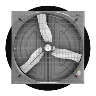
57" Assembled & Unassembled
Fan Part No. 56555-X
Bess Lab Test*
20084
20085
20086
*Bess Lab test data available at http://bess.illinois.edu/type.asp
Direct Drive Endura
2491-002 07/20
Phase
Voltage
1
230
3
230
3
230
®
Fan
Hz
Full Speed RPM
60
630
60
630
50
630
MV2491B
Advertisement
Table of Contents

Subscribe to Our Youtube Channel
Related Manuals for Chore-Time Endura 56555-1 Series


Summary of Contents for Chore-Time Endura 56555-1 Series
- Page 1 57" Assembled & Unassembled ® Direct Drive Endura 2491-001 07/20 2491-002 07/20 Fan Part No. 56555-X Bess Lab Test* Phase Voltage Full Speed RPM 56555-1 20084 56555-2 20085 56555-2 20086 *Bess Lab test data available at http://bess.illinois.edu/type.asp Operating static pressure should be less than 0.25 inches water column [62 Pa]. The Fan Inlet and exhaust must be kept clear of obstructions.
-
Page 2: Table Of Contents
Contents Topic Page Safety Information ............. . . 3 DANGER: Electrical Hazard . -
Page 3: Safety Information
(“Extended Warranty Period”) with respect to certain Product parts (“Component Part”) as set forth in the table below. If such a defect is determined by Chore-Time to exist within the applicable period, Chore-Time will, at its option, (a) repair the Product or Component Part free of charge, F.O.B. -
Page 4: Unassembled Fan Component Part Numbers
Unassembled Fan Component Part Numbers Fan Blade Part No. (on Blade Spider) Unassembled 57" DD Fan Kit Part Numbers Fan Kit Part Number 56555-1U 56555-2U 56555-3U 56555-1SU 56555-2SU 56555-3SU 56555-1TU 56555-2TU 56555-3TU Phase Voltage 380-480 380-480 380-480 Cone Grill Spacing 6" [152mm] 6"... -
Page 5: Assembled Fan Component Part Numbers
Assembled Fan Component Part Numbers Assembled 57" DD Fan Kit Part Numbers Fan Kit Part Number 56555-1 56555-2 56555-3 56555-1S 56555-2S 56555-3S 56555-1T 56555-2T 56555-3T Phase Voltage 380-480 380-480 380-480 Cone Grill Ring Spacing 6" [152mm] 6" [152mm] 6" [152mm] 6"... -
Page 6: Tools Needed And Supplies
•3/16" Drill Bit •Expansion Clamp (See “Keeping Fan Shroud edges straight” on page 13) •3/8" Socket •1/2" Socket or Wrench •Side Cutters •Caulking VFD Cross Reference Part Numbers Chore-Time Part Number Invertek Model Number 56541-1-X ODE-3-120070-101A 56541-2-X ODE-3-120070-301A 56541-3-X ODE-3-140041-301A... -
Page 7: Endura® Dd Fan New Installation Planning
57" Assembled & Unassembled Direct Drive Endura® Fan Endura® DD Fan New Installation Planning Endura ® DD Fan New Installation Planning Planning the layout of the spacing between Fans is very important. Spacing too close together will cause interference between the discharge Cones. See the Invertek ODE-3 IP66 Outdoor User Guide, (MV2493) at www.choretime.com/documents, Manuals, Ventilation, Fans &... -
Page 8: Installation
Installation 57" Assembled & Unassembled Direct Drive Endura® Fan Installation Inspecting the Shroud Inspect the Shroud assembly for hardware as received. (53626) Center V-Post (48427) Magnet (53026) Magnet Side Plate Assembly Jig for Unassembled Fans (For assembled versions skip to page 12) Motor 6"... -
Page 9: Install Motor Supports
57" Assembled & Unassembled Direct Drive Endura® Fan Installation Install Motor Supports Edges Parallel .14" [3.5mm] Maximum Gap Item Description Part No. 57" DD Fan Motor Support 56502 5/16-18 x 3/4 Bolt 4412-11 5/16 Flg. Nut 46764 (4412-11) 5/16-18 x 3/4 Bolt (46764) 5/16 Flg. -
Page 10: Shroud And Shroud Components Installation
Installation 57" Assembled & Unassembled Direct Drive Endura® Fan Shroud and Shroud Components Installation 1.Assemble the four corner Bracket assemblies by threading (4412-28) Bolts into the Corner Supports as shown. Each Corner Bracket Assembly is unique. Make sure to use the appropriate Corner Support with the Bolt in the correct hole as shown. - Page 11 57" Assembled & Unassembled Direct Drive Endura® Fan Installation 2.Fasten the Cone Supports and Brackets to the Fan Motor Supports with 4 (46764) Nuts as shown. Item Description Part No. 5/16 Flg. Nut 46764 (46764) 5/16 Flg. Nut 3.Install the Top Pivot Plate Bracket (53037), Bottom Pivot Plate Bracket (53036), Fan Cone Cable (53399-1) and Eye-Bolt (30663) as shown.
-
Page 12: Bottom Shelf Installation
Installation 57" Assembled & Unassembled Direct Drive Endura® Fan Bottom Shelf Installation Center of Rough Opening Tighten until Snug only. Do not Deform the Bottom Shelf.) (53338) Bottom Shelf Outside of House Center of Bottom Shelf If the Shelf is too long Trim equal amounts from both ends. -
Page 13: Keeping Fan Shroud Edges Straight
57" Assembled & Unassembled Direct Drive Endura® Fan Installation Keeping Fan Shroud edges straight It is important when attaching the Fan to the Wall to keep edges of Shroud straight. A 600 Lb. Hand Clamp can be used to straighten Shroud if necessary. Keep edges of Shroud Straight Note: Shown without Doors for Clarity. -
Page 14: Cone Assembly
Installation 57" Assembled & Unassembled Direct Drive Endura® Fan Cone Assembly Assemble Cone Panels as shown below. Prop the Cone Panels up off the ground to ease assembly One Hole Two Holes Tabs Up Tabs Snap positively in place MV2491B... -
Page 15: Installing The Orifice Frame
57" Assembled & Unassembled Direct Drive Endura® Fan Installation Installing the Orifice Frame Rounded Tab on the Cone Important! Line up the Seam in the Orifice Frame with one of the rounded Tabs on the Cone. Orifice Frame Shown Gray for Clarity. (46764) (53611) Frame... - Page 16 Installation 57" Assembled & Unassembled Direct Drive Endura® Fan Attach the cone to the Shroud as shown below. Slip the Orifice Frame behind the Bottom Pivot Plate. Bottom Pivot Plate 5/16 Flg. Nut (46764) If necessary, slip a thin piece of metal between the Shroud and Cone and work it around the Cone to get it on.
-
Page 17: Door Assembly And Installation
57" Assembled & Unassembled Direct Drive Endura® Fan Installation Door Assembly and Installation Doors are Left and Right specific. Insert Door Pins in both Doors as shown. Push Pins in until they bottom out. (53038) Door Pin View of Back of Door View of Back of Door Door Spring... -
Page 18: Grill Installation
Installation 57" Assembled & Unassembled Direct Drive Endura® Fan Grill Installation Install the Fan Cone Grill (as shown). Attach the end of the Door Stop Cable to the bottom Grill Leg as shown. (54287) (46764) (ST99070) Door Stop Cable (46764) (54287) (46764) Door Stop Cable... -
Page 19: Check Blade Tip Clearance
57" Assembled & Unassembled Direct Drive Endura® Fan Installation Check Blade Tip Clearance Push only on inner most 2" [5.08 cm] of Shroud 1/8" [3mm] Minimum If Clearance is insufficient, check that the mounting surface is flat, and that the sides of the Shroud are straight. -
Page 20: Caulking
Installation 57" Assembled & Unassembled Direct Drive Endura® Fan Caulking Caulk both Ends of the Bottom Shelf to fill any gaps between the Shroud and the Framed opening. Caulk Both Ends of the Bottom Shelf Fan Drive (VFD) Mounting Select a location next to the Fan to install the Fan Drive. See the Invertek VFD Quick Start Guide (MV2492) that comes with the drive, or online at www.choretime.com/documents, Manuals, Ventilation, Fans &... -
Page 21: Screen Installation
57" Assembled & Unassembled Direct Drive Endura® Fan Installation Screen Installation Center Screen on the wall opening and (41561) Lag Screw angled fasten with 8 Screen Clip Washers slightly outward will allow (56671) and (41561) Lag Screws as for easier Screen removal 3/8"... -
Page 22: Control Signal Wiring
Control Signal Wiring 57" Assembled & Unassembled Direct Drive Endura® Fan Control Signal Wiring See the Invertek Quick Start Guide that comes packaged with the VFD for VFD wiring instructions. Further information is also available in the Invertek ODE-3 IP66 Outdoor User Guide (MV2493). It can be viewed online at www.choretime.com/documents, Manuals, Ventilation, Fans &... -
Page 23: Test Fan For Proper Operation
57" Assembled & Unassembled Direct Drive Endura® Fan Test Fan for proper operation Test Fan for proper operation Supply power to the VFD and check for proper operation. If the Fan turns in the wrong direction interchange any two wire connections between the drive and the motor to correct the direction of fan blade rotation. Maintenance IMPORTANT! Disconnect Power Prior To Maintaining Or Cleaning The Fan. -
Page 24: Parts Numbers (Itemized)
Parts Numbers (Itemized) Top Corner Brackets have two Notches Bottom Corner Brackets have one Notch. - Page 25 Item Qty. Description Part No. ® 57" Direct Drive Endura Fan (56555-X,-XS,-XT) Part Numbers Motor, 230V, 7A, 630RPM PMSM 56501 -1,-2,-1S,-2S,-1T,-2T,-1U,-2U,1SU,-2SU,-1TU,-2TU Motor, 230V, 7A, 630RPM PMSM 56704 -3,-3S,-3T,-3U,-3SU,-3TU 57" Fan Shroud Assembly 52925 57" Cross Rod Coupler 56339 Rivet 48936 57"...
-
Page 26: Part Numbers (Itemized) Continued
Part Numbers (Itemized) continued Used when Spacing Fans close together... - Page 27 Item Qty. Description Part No. 57" DD Endura® Fan (56555-X, -XS, -XT, -XSU, -XTU) Part Numbers 57" Left Hand Fan Door 52926L 57" Right Hand Fan Door 52926R 11** Magnet Striker Plate 53027 57" Fan Orifice Frame 53416 57" Fan Top Pivot Plate 53037 57"...
- Page 28 Page No. Description of Change Various Added Unassembled Fans 35063 For additional parts and information, contact your nearest Chore-Time distributor or representative. Find your nearest distributor at: www.choretime.com/contacts CTB, Inc. PO Box 2000 Milford, Indiana 46542-2000 USA Phone (574) 658-4101 Fax (877) 730-8825 Email: choretime@choretime.com...
Need help?
Do you have a question about the Endura 56555-1 Series and is the answer not in the manual?
Questions and answers