Table of Contents
Advertisement
Quick Links
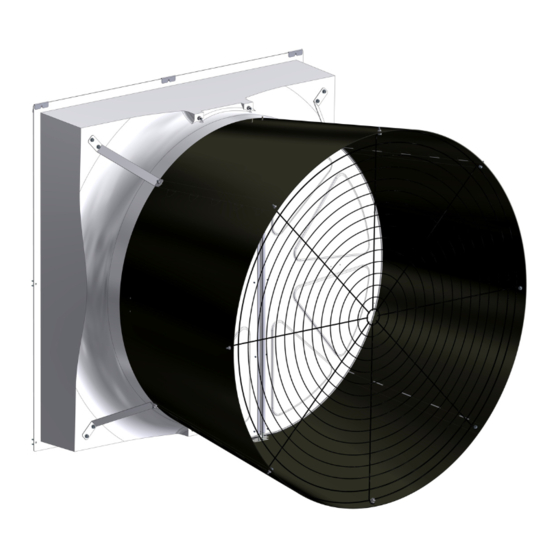
52" TURBO
Installation & Operator's Instruction Manual
Fan Type
Fan Assembly
Part No.
Standard
49740-22*
High Capacity
49740-21*
Standard
49740-42*
High Capacity
49740-41*
High Capacity
49740-51*
*Part Numbers shown are for White Fans with White Cones. Add a "B" to the Part Number example: "56258-22B" for a Black Fan w/ Black
Cone, Add a "BW" for a Black Fan w/ White Cone.
January 2023
Fan with HYFLO
®
& 4 Piece Cone
Sub Assembly
Bess Lab
Part No.
Test No.
56258-22
04334
56258-21
04312
56258-42
04335
56258-41
04318
56258-51
Voltage
Hz
230
60
230
60
200-230/400-460
60
200-230/400-460
60
200-230/380-415
50
Door
®
Ph HP
Fan
cfm @
rpm
.10" w.c.
1
1.5
564
24900
1
1.5
611
27700
3
1.5
566
24800
3
1.5
615
27900
3
1.5
cfm/Watt
.10" w.c.
20.8
18.3
20.5
18.2
MV2477C
Advertisement
Table of Contents

Subscribe to Our Youtube Channel
Related Manuals for Chore-Time 52 TURBO


Summary of Contents for Chore-Time 52 TURBO
- Page 1 52" TURBO Fan with HYFLO Door ® ® & 4 Piece Cone Installation & Operator’s Instruction Manual Fan Type Fan Assembly Sub Assembly Bess Lab Voltage Ph HP cfm @ cfm/Watt Part No. Part No. Test No. .10" w.c. .10" w.c. Standard 49740-22* 56258-22...
-
Page 2: Personnel Requirements
Safety Safety Warning This product has inherent dangers, which can cause damage or loss to persons or equipment if the warnings in this manual are not adhered to. Please read and follow all instructions. Personnel Requirements This product must only be used by persons adequately trained in the hazards, dangers, and risks of the equipment. -
Page 3: Residual Risks
Safety Residual Risks Despite the level of caution taken and the incorporation of safeguards, some risks will remain. This product has the following hazards: Hazard Safeguard Operator Requirement Cutting or trapping Fixed guards Maintain all fixed guards in proper location and good Ejection of parts condition Stability... -
Page 4: Limited Warranty
Chore-Time provides for an extension of the aforementioned Warranty period (“Extended Warranty Period”) with respect to certain Product parts (“Component Part”) as set forth in the table below. If such a defect is determined by Chore-Time to exist within the applicable period, Chore-Time will, at its option, (a) repair the Product or Component Part free of charge, F.O.B. - Page 5 Fan and Fan Framing Dimensions Fan and Fan Framing Dimensions Item Description 59” [149.86 cm] 67.81" [172.2 cm] 53” [134.91 cm] 7.5" [19.1 cm] 59" [149.86 cm] 8.3 [21.11 cm] Figure 1.Fan and Framing Dimensions Planning the layout of the spacing between fans is very important. A Minimum of 13" between Fan rough openings is required so the Cones do not interfere.
-
Page 6: Installation
Installation Installation Fan Mounting Insert the Fan Assembly in the wall opening. Rotate the Fan Blade by hand and check to make sure that there is a minimum of 1/8" Blade clearance all the way around the Shroud orifice. Shift the Fan around in the wall opening, if needed, to achieve at least 1/8"... - Page 7 Installation Locate the three holes across the top Fan Shroud flange (Item 5, Figure 4). Line up the Screen Retainers included in the Parts Package (Item 1) with these three holes, slip them over the top Fan Shroud flange, and using (3) 1/4 x 1-3/4 Lag Screws included in the Parts Package attach the Fan to the Wall (Step 1). In each of the remaining 5 holes in the Fan Shroud flange, use a 1/4 x 1-3/4 Lag Screw, two Nylon Washers, and a Screen Clip, all included in the Parts Package, to secure Fan to the Wall as shown below in Step 2.
- Page 8 Installation Assembling the Cone A. Lay one panel flat with the tabs oriented to the left. Place a 2x4 or similar underneath the panel just left of the slots on the right side. B. Place tabs of a second panel into the slots of the first and ensure they 'pop' together fully. C.
- Page 9 Installation Attaching the Cone 1.Orient the the Cone with the Inward pointing Bolt toward the bottom as shown. 2.Hang the Cone on the Cone Bolts as shown in Figure 6. Seams between Cone Panels should be oriented Important! toward corners of Shroud as shown. 3.Secure the Cone by attaching the Top (2) Cone Brackets to the Bolts in the Cone with additional 5/16-18 Nuts (46764) as shown.
-
Page 10: Installing The Belt
Installation Attaching the Door Stop Cable Secure the Door Stop Cable to the bottom Grill/Cone Bolt using two (ST99070) Washers and a (46764) Nut. (46764) (ST99070) Door Stop Cable (46764) (54287) Door Stop Cable even with the edge of Cone Figure 8.Attaching Door Stop Cable Installing the Belt Install the belt as shown in Figure 11. - Page 11 Installation Installing the Screen Orient the Screen as shown below with the fine mesh section on the outside of the Fan. Slide the top of the Screen under the Screen Retainers (Step 1, Figure 10) and turn the bottom Screen Clip to hold the Screen in place (Step 2).
- Page 12 Wiring Wiring 1. See Wiring diagram on Motor for Motor electrical connections. Follow local, state, and national electrical codes for wiring 2. Install an electrical disconnect within reach of each Fan. 3. Route the motor cord (not supplied) toward the upper left corner of the Fan and attach the cord to the Motor Mount using the Cable Tie—included in the hardware package.
-
Page 13: Maintenance
Maintenance Maintenance •Disconnect Power Prior To Maintaining Or Cleaning The Fan. The fan may start automatically causing serious injury or death. • Service and repair of fans should be done only by a qualified technician. • Keep the Fan clean for maximum life and best performance. Do Not spray water on Fan Shaft Bearings, Belt Tensioner, or the Motor. - Page 14 Maintenance Belt Tensioner Position When the Belt is installed the Tensioner will rotate to a set position. The notches on the outside wheel of the Tensioner should line up with the etched mark (A,B, or C per chart) on the inside wheel of the Tensioner based on the chart below.
- Page 15 This page left blank intentionally..MV2477C...
-
Page 16: Part Numbers
Part Numbers See Decals next page... - Page 17 Itemized Part Numbers RPM Sensor Detail Fan Part No. ® ® 52" TURBO Fan with HYFLO Door 56258-XX (Sub Assembly) See page 1 for ordered Fan Part Number Item Part Description Part No. Models-XX Item Part Description Part No. Models-XX Motor, 1.5H, 1.67SF 3PH-60HZ, 230/460V, 56102 -42,-42B,-42BW,-41,-41S,-41B,-41BW,-41BS,-51,-51B,-51BW...
-
Page 18: Revisions To This Manual
Note: The original, authoritative version of this manual is the [English] version produced by CTB, Inc. or any of its subsidiaries or divisions, (hereafter collectively referred to as "CTB"). Subsequent changes to any manual made by any third party have not been reviewed nor authenticated by CTB. Such changes may include, but are not limited to, translation into languages other than [English], and additions to or deletions from the original content.
Need help?
Do you have a question about the 52 TURBO and is the answer not in the manual?
Questions and answers