
Related Manuals for Epson EU-T432


Summary of Contents for Epson EU-T432
- Page 1 Confidential Technical manual Thermal printer unit EU-T432 Issued Date Issued by English 4013753...
- Page 2 On the earlier of (a) termination of your relationship with Seiko Epson, or (b) Seiko Epson’s request, you must stop using the confidential information. You must then return or destroy the information, as directed by Seiko Epson.
- Page 3 To assure the safe operation of this product, carefully observe the specifications as well as the notes provided below. Seiko Epson Corporation will not bear any responsibility for any damage or injuries arising from use of this product that is not in accordance with the specifications and the notes provided below.
-
Page 4: About This Manual
This chapter contains repair levels, repair procedures, and troubleshooting. Chapter 6 Assembly and Disassembly This chapter contains assembly and disassembly for the units and modules of the EU-T432. Appendix The appendix contains the exploded and adhesive diagrams of the EU-T432. Symbols Notes in this manual are identified by their level of importance, as defined below. -
Page 5: Table Of Contents
Confidential Contents About This Manual ........... . v Symbols . - Page 6 Confidential EU-T432 Technical Manual LED Display ............3-13 POWER LED (Power Supply Error): Green .
- Page 7 EU-T432 Lubrication Diagram ........
-
Page 8: Chapter 1 Features And Specifications
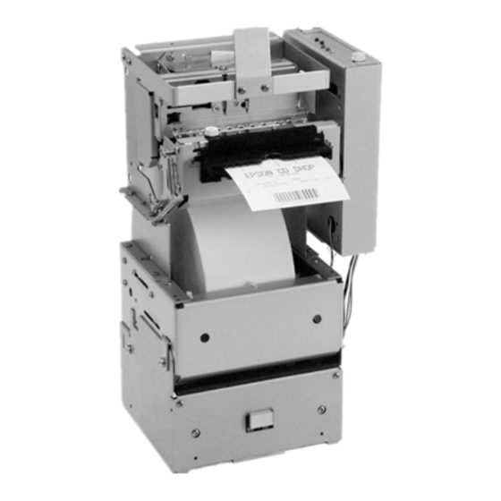
Confidential EU-T432 Technical Manual Chapter 1 Features and Specifications Features The EU-T432 is designed to be used for kiosks and cash dispensers. The features of the EU-T432 are as follows: High speed receipt issuing: 150 mm/s {5.9"/s} maximum High reliability:... -
Page 9: System Configuration And Module Names
Confidential System Configuration and Module Names The whole systems is called the “EU-T432.” The EU-T432 consists of four modules and the configuration of the modules are shown below: printer module cut sheet presenter module control circuit board module paper roll supply module... -
Page 10: Specifications
Confidential EU-T432 Technical Manual Specifications The basic specifications of the EU-T432 are shown below. Refer to the specifications for the EU-T432 issued by Seiko Epson Corporation for more details. Table 1.1 Specifications Specification Item Paper roll Outside diameter 152.4 mm {6"} (When equipped with an optional part: 203 mm {8")) -
Page 11: Module Combinations And Specifications
Confidential Table 1.1 Specifications Specification Item Environmental condition Operating temperature 0 to 50°C Operating humidity 10 to 80% RH 34°C 80% 40°C 58% 50°C 35% Print quality is guaranteed. Operation is 5 10 guaranteed. Module Combinations and Specifications: Table 1-2 Module Combinations and Specifications 6 inch type Item 8 inch type... -
Page 12: Chapter 2 Operation Principles
Chapter 2 Operation Principles Outline of Mechanism The EU-T432 consists of four modules: the paper roll supply module, the printer module, the cut sheet presenter module, and the control circuit board module. Paper Roll Supply Module The paper roll supply module holds a large diameter paper roll and guides the paper to the printer module. -
Page 13: Paper Holding Section
Confidential Paper Holding Section The paper roll holding mechanism is a shaft support type. The paper roll holding section consists of the removable shaft, roll paper, the holder, roll paper A (for the inner diameter of the paper core: 25.4 mm {1 inch}) that fits the size of the paper roll core used, the holder, roll paper shaft that supports the shaft, roll paper and the plate, roll paper guide that holds the sides of the paper roll. -
Page 14: Printer Module
Confidential EU-T432 Technical Manual Printer Module The printer module has a printing mechanism with the paper feeding and a cutting mechanism to cut the paper. The printer consists of the following six mechanisms: the drive force transmission mechanism, the paper feed mechanism, the printing mechanism, the paper guide mechanism, the detector mechanism, and the autocutter mechanism. -
Page 15: Paper Feed Mechanism
Confidential This printer uses a 4-phase bi-polar stepping motor driven by 24 V voltage controlled 2-2 phase excitation. The maximum drive frequency of 2-2 phase excitation is 1200 pps. [pps: pulses per second] Paper Feed Mechanism This mechanism consists of the paper feed mechanism and the platen-open mechanism. Paper feed mechanism The paper feed mechanism consists of the platen (paper feed roller) and the thermal head. - Page 16 Confidential EU-T432 Technical Manual Platen-open mechanism The platen-open mechanism is used for the following purposes: • Paper loading when using the printer with the curved path type. (Excluding when using semi-autoloading mode.) • Removing a paper jam when the paper jam has occurred •...
-
Page 17: Printing Mechanism
Confidential Printing Mechanism This mechanism consists of the thermal head which has the head heating elements arranged in a series and has a driver IC for controlling voltage to the head heating elements, the platen which is also used for the paper feed mechanism as well as this mechanism (the thermal head is also used for both mechanisms), and the spring, press head. - Page 18 Confidential EU-T432 Technical Manual Data input and printing The thermal head consists of the head heating elements, the head driver, which controls or drives the head heating elements, and the thermistor, which detects the temperature of the thermal head. The serial print data input from Data In (DI1) is synchronized to the CLOCK (CLK) input, and temporarily placed in the SHIFT REGISTER.
-
Page 19: Paper Guide Mechanism
Confidential Paper Guide Mechanism This mechanism consists of the paper guide mechanism. The paper path consists of the paper guide, straight, front and the paper guide, straight, back. The paper path is shown below. paper platen paper guide, straight, front paper guide, straight, back Figure 2-9 Paper path Detector Mechanism... - Page 20 Confidential EU-T432 Technical Manual The transparent photo sensor is in a high state (HI) when the paper is present, and in a low state (LOW) when the paper is not present because the lever, paper detector blocks light to the sensor. When the end of the thermal paper passes through the paper guide, the lever, paper detector operates as shown in Figure 2-11.
- Page 21 Confidential Platen-open detector mechanism The platen-open detector mechanism has a microswitch which detects whether the platen is open (printing impossible because the thermal head is away from the platen) or closed (printing possible). The microswitch can be OFF only when the frame, platen is perfectly closed, and at all other times is ON.
-
Page 22: Autocutter Mechanism
Confidential EU-T432 Technical Manual Black marks are detected through changes in output level from the reflective photo sensor. The changes in reflectivity between the pre-printed black marks and blank areas of the thermal paper cause the amount of light returning to the sensor to vary; then the sensor output level is also varied as shown in Figure 2-15. - Page 23 Confidential Movable cutter blade mechanism This mechanism is mounted on the frame, base. The drive force transmission mechanism is on the cover, cutter side. The motor, cutter is a DC brush motor on the gear, cutter motor. It supplies the power and is attached on the cover, cutter with screws.
- Page 24 Confidential EU-T432 Technical Manual Autocutting operation The autocutter will operate when the frame platen unit is closed and a paper is loaded. (The frame platen unit can be closed when the movable cutter blade, full is in the standby position.
- Page 25 Confidential Note: If the movable cutter blade, full cannot be returned to the home position because of foreign matter locking the blade when powered by the motor, rotate the knob on the gear, cutter worm with a tool such as a ball-point pen or tweezers to move the movable cutter blade, full to the home position. The window on the cover, cutter can be used to check if the movable cutter blade, full has returned to the home position.
-
Page 26: Cut Sheet Presenter Module
Confidential EU-T432 Technical Manual Cut Sheet Presenter Module The cut sheet presenter module has a mechanism to feed the paper printed and cut by the printer module to the paper exit. Figure 2-21 Appearance of cut sheet presenter module Paper Feeding Operation (With a Loop) A paper feeding operation is performed at the same time with the start of the paper feeding of the printer module. - Page 27 Confidential While the tip of the paper sent from the printer module is in the standby state between the roller, presenter and the roller, cutting paper hold, the paper is continuously fed from the printer module. The paper pushes up the paper guide, upper and temporarily forms a loop. autocutter loop paper guide, upper...
-
Page 28: Detector Mechanism
Confidential EU-T432 Technical Manual Paper Feeding Operation (Without a Loop) The cut sheet presenter module can feed paper without forming a loop. paper guide, upper roller, cutting paper hold paper exit roller, presenter motor, cutting paper feed Figure 2-25 Cut Sheet Operation without Loop Note: During paper feeding operations without a loop, do not pull out the paper. -
Page 29: Control Circuit Board Module
Confidential Control Circuit Board Module The control circuit board module controls all functions of each module and has the interface connectors and the power supply terminals. Each function can be set by using the DIP switches and the memory switches. DIP switch 2 DIP switch 1 Figure 2-26 Appearance of the control circuit board module... - Page 30 Confidential EU-T432 Technical Manual Table 2-2 Interface Selection Interface Switch No. 2 Switch No.3 Parallel interface (IEEE1284) Serial interface (RS232) Optional interface ON or OFF Table 2-3 Baud Rate Selection Transmission speed (bps) Switch No.7 Switch No.8 4800 9600 19200...
-
Page 31: Memory Switches
GS ( E E E E command, and also can be changed by using the MEMSW.exe included GS ( with EPSON Advanced Windows Drivers.) The settings of the memory switches are as follows: Table 2-8 Memory Switch 1 ON (1) OFF (0) SW No. - Page 32 Confidential EU-T432 Technical Manual Table 2-10 Memory Switches 6 SW No. Function Default setting 1 to 2 Fixed to OFF OFF(0) Reserved Speed has priority Power consumption over power has priority over OFF (0) (*1) Print speed control consumption...
- Page 33 Confidential Table 2-11 Memory Switch 7 ON (1) OFF (0) SW No. Function Default setting Fixed to OFF OFF(0) Reserved Setting for the 2 and 3 secondary paper OFF(0) (*1) Refer to Table 2-12 near-end position Operation after Ejects fully Clamps cutting OFF(0) (*2)
- Page 34 Confidential EU-T432 Technical Manual Table 2-13 Memory Switch 8 ON (1) OFF (0) SW No. Function Default setting 1 to 2 Refer to 2-14 OFF(0) Print control mode Backward paper Enabled Disabled OFF(0) (*1) feeding Autocutter Not installed Installed OFF(0)
-
Page 35: Chapter 3 Handling
Transport Precautions When shipping the printer, use antistatic packing materials. Remove the paper roll when transporting the EU-T432. Make sure to close the paper roll supply module, the platen unit of the printer module, and the cut sheet presenter module when transporting. -
Page 36: Installation Precautions
15 minutes for them to cool. Since the EU-T432 contains permanent magnets (in the motor) as well as electromagnets, they should not be used in an environment with excessive dirt, dust, or metallic dust. - Page 37 15 minutes for them to cool. Since the EU-T432 contains permanent magnets as well as electromagnets in the motor, they should not be used in an environment with excessive dirt, dust and metallic dust.
-
Page 38: Storage Precautions
Do not store the printer in environments with excessive dust, high temperature, high humidity, or in direct sunlight. Before storing the EU-T432 for an extended time, remove the paper and wipe off dirt and dust; then clean parts such as the platen and the thermal head of the printer module with alcohol. -
Page 39: Cut Sheet Presenter Module
Confidential EU-T432 Technical Manual Cut Sheet Presenter Module 1. Put your fingers on the top and bottom of the cut sheet presenter module; then pull the module up at an angle (in the direction of arrow B) to slide it. -
Page 40: Loading And Removing Paper Roll
Follow the steps below to load or remove the paper roll. See Figure 3-3 on page 3-7. Note: Use only the paper specified in the EU-T432 specifications issued by Seiko Epson Corporation. Loading paper for the paper roll supply module 1. - Page 41 Confidential EU-T432 Technical Manual 6. Turn the paper roll supply module back to its original position until it is locked by the frame open lever with a click sound. Then turn it back so that the plate, paper guide is not deformed.
- Page 42 Confidential Loading paper for printer module Follow the steps below to load the paper for the printer module from the paper roll supply module. 1. Cut the edge of the paper as shown below. Figure 3-4 Shape of paper edge 2.
-
Page 43: Removing Paper
Confidential EU-T432 Technical Manual Removing Paper Follow one of procedures below to remove the paper roll. Removing paper using BACK and FEED buttons You can remove the paper using the BACK and FEED buttons. If you push the FEED button while holding down the BACK button, the paper will be fed backwards. -
Page 44: Removing Jammed Paper From The Printer Module
Confidential Removing Jammed Paper From the Printer Module 1. Open the cut sheet presenter module. 2. Turn the lever, platen to open the platen unit and remove the jammed paper. Paper NE Detector Setting This detector is mounted on the paper roll supply module. By adjusting the position of the detector, the detector can detect the amount remaining on the paper roll at the setting value. - Page 45 Confidential EU-T432 Technical Manual screw, paper NE detector for 8 inch type 1 2 3 4 5 6 7 8 9 (hole No,) paper NE detector (back side) 1 to 8 for 6 inch type paper roll supply module Figure 3-5 Setting of the paper NE detector Rev.
-
Page 46: Self Test
Confidential Self Test The EU-T432 has self test functions. Follow the steps below to perform the self tests. Performing the Self Test 1. With the paper loaded, turn on the power while holding down the FEED button on the panel switch. -
Page 47: Errors
Confidential EU-T432 Technical Manual Errors LED Display The LED indications indicate the following: the POWER LED for power supply error, the PAPER LED for paper-out error and the ERROR LED for various kind of errors. For the LED position, see Figure 3-6 “Performing the self test,”... - Page 48 Confidential Possible recovery error Table 4-7 Possible Recovery Error Error type LED flashing pattern Cause Platen open error Platen unit is open during printing. Approx. 320 ms Approx. 5.12 s Autocutter error Autocutter malfunction Approx. 320 ms Approx. 5.12 s Black mark sensor No black mark is detected even after a certain amount detection error...
-
Page 49: Chapter 4 Maintenance
Confidential EU-T432 Technical Manual Chapter 4 Maintenance To keep the printer in peak working condition, extend its life for a long term, and prevent operational failures, follow the maintenance procedures below. Cleaning CAUTION: • Never clean the thermal head with solvents other than the specified ones, since other solvents could damage the thermal head or cause the malfunction of parts. -
Page 50: Removing Stains (Except For The Thermal Head)
Confidential Removing Stains (Except for the Thermal Head) The areas where the paper is fed will be stained or collect dust after printing for a long time because of paper dust and heat sensitive materials contained in the paper. Especially, if paper feed rollers, the platen, or the paper detectors are not clean, a malfunction in paper feeding or paper detection may occur. -
Page 51: Inspection
Confidential EU-T432 Technical Manual Inspection The maintenance and inspection procedures for the printer fall into two categories. One is “Daily checks” for the printer user, and the other is “Periodic checks” for someone with more technical knowledge. Maintenance and inspection procedures should be carried out by properly qualified personnel. -
Page 52: Lubrication
The lubricants for the printer are chosen based on technical information analysis and tests on various lubricants by EPSON. The lubricants are available in 40 cc (gr.) plastic containers (the minimum supply unit). Both G-36 and G-15 are used on this printer. -
Page 53: Lubricant List
Confidential EU-T432 Technical Manual Lubricant List Table 4-3 Lubricant List Type Name Quantity Commercial availability G-15 40 gr Grease Epson exclusive product Grease G-36 40 gr Tools Table 4-4 Tool List Tool name Commercial availability Brush #1 Cleaning brush Crosshead screwdriver #0, 1 and 2 ET holder No. -
Page 54: Chapter 5 Repair
Confidential EU-T432 Technical Manual Chapter 5 Repair Repairs are divided into two levels (A and B) in consideration of the degree of difficulty of repair. The person who repairs the printer should perform the proper repair procedures, depending on the individual technical knowledge and skills. -
Page 55: Troubleshooting
Confidential Troubleshooting Use troubleshooting procedures in the table below when problems occur. Table 5-1 Troubleshooting Phenomenon Condition Cause Level Where/how to check Procedure Power connector is See if the power Connect the power Power (24 V) is performance disconnected. connector is connector again. - Page 56 Confidential EU-T432 Technical Manual Table 5-1 Troubleshooting Phenomenon Condition Cause Level Where/how to check Procedure PAPER LED is Self test standby Self test is in the Check if the self test Press paper feeding flashing. state standby state printing is completed.
- Page 57 Confidential Table 5-1 Troubleshooting Phenomenon Condition Cause Level Where/how to check Procedure Printing Nothing is (1) The head FFC Check whether the Connect the head operation does printed. connection head FFC is connected FFC properly. not work. failure properly. (2)The head FFC See or check with an Replace the head signal line is...
- Page 58 Confidential EU-T432 Technical Manual Table 5-1 Troubleshooting Phenomenon Condition Cause Level Where/how to check Procedure •Check the printing Printing is faint. All printing color is Change the setting Printing density faint. density setting of the of the printing setting is set to light.
- Page 59 Confidential Table 5-1 Troubleshooting Phenomenon Condition Cause Level Where/how to check Procedure •Load the paper Paper is not Paper is not fed (1)The paper roll Check if the paper is fed. smoothly. supply module pulled out smoothly. properly. •Replace the paper does not (The paper tension oscillate...
- Page 60 Confidential EU-T432 Technical Manual Table 5-1 Troubleshooting Phenomenon Condition Cause Level Where/how to check Procedure •Replace the Paper feeding The character Check the power (3)Abnormal input pitch is spacing is not supply voltage, input signal or paper control circuit defective.
-
Page 61: Chapter 6 Assembly And Disassembly
Confidential EU-T432 Technical Manual Chapter 6 Assembly and Disassembly Small Parts Abbreviation All small parts are represented by the abbreviations listed below Table 6-1 Small Parts Abbreviations 記号 記号 部品名称 部品名称 記号 記号 部品名称 部品名称 Retaining ring E-type C-ring Crescent ring C.B. -
Page 62: Disassembly
Confidential Disassembly For disassembly, follow the assembly procedures described in “Assembly” in reverse sequence. Disassembly of the modules beyond the level show in the exploded diagrams at the end of this manual may result in damage to the modules and their functions. Assembly The assembly process is divided into pre-assembly and main assembly. -
Page 63: Installation Of The Printer Module
Confidential EU-T432 Technical Manual Installation of the Printer Module Pre-assembly A: Paper guide,straight, back unit Reassembly Part name Assembly procedure step Paper detector assembly Slide the paper detector assembly onto the paper guide, straight, back. Paper guide, straight, back paper detector... -
Page 64: Pre-Assembly B: Frame, Platen, Straight Unit, B
Confidential Pre-assembly B: Frame, platen, straight unit, B Reassembly Part name Assembly procedure step Frame, platen Lock lever assembly Install the lock lever assembly on the frame, platen, and secure it with a C.B.B-tite (M2 × × × × 6) ×... - Page 65 Confidential EU-T432 Technical Manual Pre-assembly B Reassembly Part name Assembly procedure step Push plate, platen, B Install the push plate, platen, B to the frame, platen and secure it with a C.C.P-tite (M2.5 × × × × 6) × 1 screw.
- Page 66 Confidential Pre-assembly B Reassembly Part name Assembly procedure step Platen, straight assembly Bearing, platen After Installing the platen, straight assembly to the frame, platen, install the × 1 R.E. (2.5) bearing, platen from the outside of the frame, platen; then secure it with an R.E.
-
Page 67: Pre-Assembly C: Cutter Motor Assembly
Confidential EU-T432 Technical Manual Pre-assembly C: Cutter motor assembly Reassembly Part name Assembly procedure step Microswitch Lead wire, paper cutter Solder the white lead wire of the lead wire, paper cutter to the microswitch. black microswitch white lead wire, paper cutter... -
Page 68: Pre-Assembly D: Cutter, Cover Sub-Unit
Confidential Pre-assembly D: Cutter, cover sub-unit Reassembly Part name Assembly procedure step Cutter, cover sub-assembly ② Gear, cutter worm Lubricate with G-36 the bore of the gear, cutter worm and the point where the gear, cutter worm comes in contact the cutter, cover sub- assembly;... - Page 69 Confidential EU-T432 Technical Manual Pre-assembly D Reassembly Part name Assembly procedure step Shaft, reduction A/C Insert the shaft, reduction A/C to the bores of the gear, reduction A/C and the gear, cutter worm. gear, cutter worm shaft, reduction A/C gear, reduction A/C spring, cutter clutch <Check>...
- Page 70 Confidential Pre-assembly D Reassembly Part name Assembly procedure step Cutter drive gear After lubricating the shaft on the cutter cover sub-assembly with G-36, sub-assembly install the cutter drive gear sub-assembly and the plain washer Plain washer (3 × × × × 0.5 × × × × 7) × 1 on the shaft;...
-
Page 71: Pre-Assembly E: Cutter Unit, B
Confidential EU-T432 Technical Manual Pre-assembly E: Cutter unit, B Reassembly Part name Assembly procedure step Cutter cover sub-unit Cutter frame assembly Pass the lead wire, paper cutter through the hole on the cutter frame C.B.S-tite (M3 × × × × 5) ×... - Page 72 Confidential Pre-assembly E Reassembly Part name Assembly procedure step Emergency cutter, full, B Install the emergency cutter, full, B to the cutter cover sub-unit with C.B.(M2 × × × × 2.5) × 2 screws. mounting position C.B.(M2 × 2.5) emergency cutter, full, B <Check>...
-
Page 73: Pre-Assembly F: Black Mark Detector Sub-Assembly (Option)
Confidential EU-T432 Technical Manual Pre-assembly F: Black mark detector sub-assembly (option) Reassembly Part name Assembly procedure step Black mark (B.M.) sub- assembly Paper guide Install the B.M. detector sub-assembly in one of the two detector C.P-tite F screw (M2 × × × × 3) mounting holes on the paper guide, and secure it with a screw. -
Page 74: Main Assembly A: Motor, Paper Feed, Receipt, B And Platen Detector
Confidential Main Assembly A: Motor, paper feed, receipt, B and Platen detector Reassembly Part name Assembly procedure step Frame assembly Motor, paper feed, receipt, Align the motor, paper feed, receipt, B with the mounting position on the frame assembly and secure it with scerws. C.B.S-tite (3 ×... - Page 75 Confidential EU-T432 Technical Manual Main Assembly A Reassembly Part name Assembly procedure step <Check> Tightening torque: 147 to 196 mN•m {1.5 to 2.0 kg•cm} After installing the platen detector assembly, arrange the lead wires. lead wires Rev. A Assembly and Disassembly 6-15...
-
Page 76: Main Assembly B: Paper Guide, Straight, Front And Paper Guide, Straight, Back Unit
Confidential Main Assembly B: Paper guide, straight, front and Paper guide, straight, back unit Reassembly Part name Assembly procedure step Paper guide, straight, front × 2 Pin, guide, straight Insert the pin, guide, straight into the holes on the paper guide, straight, front. - Page 77 Confidential EU-T432 Technical Manual Main Assembly B Reassembly Part name Assembly procedure step <Check> Tightening torque: 441 to 490 mN•m {4.5 to 5.0 kg•cm} The dowels on the paper guide, straight, back unit fit securely into the holes on the frame assembly.
-
Page 78: Main Assembly C: Frame, Platen, Straight Unit
Confidential Main Assembly C: Frame, platen, straight unit Reassembly Part name Assembly procedure step Lubricate the dowel on the frame assembly with G-36. Lubricate the point where the frame assembly contacts with the lock lever assembly with G-15. Frame, platen, straight unit, Install the frame, platen, straight unit, B to the frame assembly. - Page 79 Confidential EU-T432 Technical Manual Main Assembly C Reassembly Part name Assembly procedure step <Check> Hook the longer edge of the spring, lever into the groove on the lever, platen. Make sure not to deform the spring, lever. groove longer edge ×...
-
Page 80: Main Assembly D: Thermal Print Head Assembly
Confidential Main Assembly D: Thermal print head assembly Reassembly Part name Assembly procedure step Thermal print head Install the thermal print head assembly in the grooves on the frame assembly assembly. thermal print head assembly frame assembly <Check> When handling the thermal print head assembly, use proper body grounding procedures to avoid static electricity. -
Page 81: Main Assembly E: Plate, Pressure Spring
Confidential EU-T432 Technical Manual Main Assembly E: Plate, pressure spring Reassembly Part name Assembly procedure step Plate, pressure spring Circuit board assembly Install the circuit board to the plate, pressure spring, and secure it with C.B.S-tite (M2.5 × × × × 4) ×... - Page 82 Confidential Main Assembly E Reassembly Part name Assembly procedure step <Check> Make sure that the lead wires, such as those for the paper detector assembly are not caught on anything when installing the spring, press head. Make sure that the lead wires of the paper detector assembly and the paper detector assembly are passed under the plate, pressure spring.
-
Page 83: Main Assembly F: Fixing Plate, The Gear, Reduction And Gear, Idler
Confidential EU-T432 Technical Manual Main Assembly F: Fixing plate, the Gear, reduction and Gear, idler Reassembly Part name Assembly procedure step Fixing plate Install the fixing plate to the frame assembly, and secure it with the screw C.B.S-tite (M3 × × × × 5) ×... -
Page 84: Main Assembly G: Cutter Unit
Confidential Main Assembly G: Cutter unit Reassembly Part name Assembly procedure step Cutter unit, B Install the cutter unit, B to the frame assembly and secure it with screws, C.B.S-tite (M3 × × × × 5) × 2 while the lead wire, paper cutter is passed through the hook on the frame assembly. -
Page 85: Assembly H: Arranging The Lead Wires
Confidential EU-T432 Technical Manual Assembly H: Arranging the lead wires Reassembly Part name Assembly procedure step Insert the lead wire connectors to the connectors on the circuit board. connector for the platen detector assembly variable resistor connector for the motor, paper feed,... -
Page 86: Main Assembly I: Cable, Printer And Cable, Head
Confidential Main Assembly I: Cable, printer and Cable, head Reassembly Part name Assembly procedure step Cable, head Insert the cable, head in the connector on the thermal print head assembly. <Check> Make sure that the cable, head is oriented properly when connecting. Make sure that the cable, head is inserted securely Cable, printer Insert the cable, printer in the connector on the circuit board assembly. -
Page 87: Assembly J: Black Mark Detector Adjustment
Confidential EU-T432 Technical Manual Assembly J: Black mark detector Adjustment Adjustment Adjustment procedure Adjustment point step Connect the FFC terminal No.12 to an oscilloscope to display the output power voltage of the B.M. detector on the oscilloscope screen. Input DC5 V to the FFC terminal No. 13. -
Page 88: Main Assembly K: Cover, Cable
Confidential Main Assembly K: Cover, cable Reassembly Part name Assembly procedure step Loosen C.B.S-tite (M3 × × × × 5) on the cutter unit, B. C.B.S-tite (M3 × 5) Pass the cable, head and the cable printer through the hole on the Cover, cable cover, cable. -
Page 89: Main Assembly L: Cover, Gear
Confidential EU-T432 Technical Manual Main Assembly L: Cover, gear Reassembly Part name Assembly procedure step Loosen the lower C.B.S-tite (M3 × × × × 5) that secures the motor, paper feed, receipt, B. C.B.S-tite (M3 × 5) Cover, gear Hook the cover, gear to the frame, main and the shaft, frame platen while aligning with the mounting positions, and secure it. -
Page 90: Installation Of The Other Modules
Confidential Installation of the Other Modules Pre-assembly A: Frame, paper supply assembly Reassembly Part name Assembly procedure step Secure the frame, paper supply assembly with C.B.S-tite (M3 × × × × 5). Frame, paper supply × 1 assembly C.B.S-tite (M3 × × × × 5) ×... - Page 91 Confidential EU-T432 Technical Manual Reassembly Part name Assembly procedure step C.B (M4 × × × × 16) × 1 (4.3 × × × × 0.8 × × × × 8) Attach a P. washer and the collar, screw holder to a C.B (M4 ×...
- Page 92 Confidential Reassembly Part name Assembly procedure step Power supply connector Remove the switch connector from the power supply connector × 1 assembly assembly, and insert it to the hole on the frame, paper supply. At this C.B (M3 × × × × 4) ×...
- Page 93 Confidential EU-T432 Technical Manual Reassembly Part name Assembly procedure step × 2 Wire band SKB-85 Pass the lead wires for the power supply connector through the square hole on the frame, paper supply and secure them with wire bands at two places.
-
Page 94: Pre-Assembly B: Roll Paper Holder Unit
Confidential Pre-assembly B: Roll paper holder unit Reassembly Part name Assembly procedure step Roll paper holder Attach the spring, open lever to the convex parts on the frame, open reinforcement assembly × 1 lever on the roll paper holder reinforcement assembly. ×... - Page 95 Confidential EU-T432 Technical Manual Reassembly Part name Assembly procedure step × 1 NE detector assembly Connect the lead wires, NE detector to the NE detector assembly.NE. Lead wire, NE detector × 1 × 1 Cover, NE detector Attach the NE detector assembly to the cover, NE detector away from the ×...
- Page 96 Confidential Reassembly Part name Assembly procedure step Roll paper holder R Attach the spring, roll paper holder to the roll paper holder R assembly (or assembly (for a 6 inch roll paper holder R assembly, B). × 1 paper roll diameter) Roll paper holder R assembly, B (for a 8 inch ×...
- Page 97 Confidential EU-T432 Technical Manual Reassembly Part name Assembly procedure step Roll paper holder L Attach the spring, roll paper holder to the roll paper holder L assembly (or assembly (for a 6 inch roll paper holder L assembly, B). × 1...
- Page 98 Confidential Reassembly Part name Assembly procedure step × 3 Wire band SKB-85 Fasten the lead wire, NE detector to the frame with the wire band SKB-85 at three points. Take out the connector of the lead wire, NE detector trough the round hole on the frame.
-
Page 99: Pre-Assembly C: Roll Paper Supply Module
Confidential EU-T432 Technical Manual Pre-assembly C: Roll paper supply module Reassembly Part name Assembly procedure step frame, paper supply unit× 1 Place the frame, paper supply unit on the roll paper holder unit aligning × 1 Roll paper holder unit the hole positions. -
Page 100: Pre-Assembly D: Presenter Table Assembly
Confidential Pre-assembly D: Presenter table assembly Reassembly Part name Assembly procedure step × 1 Table, presenter Attach the circuit board to the table, presenter and secure it with a C.B.P- P. washer (4 × × × × 0.8 × × × × 10) × 1 tite (M3 ×... -
Page 101: Pre-Assembly E: Presenter Frame, Right Assembly
Confidential EU-T432 Technical Manual Pre-assembly E: Presenter frame, right assembly Reassembly Part name Assembly procedure step × 1 Secure the frame, presenter, middle and the frame, presenter, right with Frame, presenter, middle Frame, presenter, right × 1 a C.B.S-tite (M3 × × × × 5) screw and a C.B.S-tite (M3 × × × × 12) screw. -
Page 102: Pre-Assembly F: Presenter Frame, Left Assembly
Confidential Pre-assembly F: Presenter frame, left assembly Reassembly Part name Assembly procedure step × 1 Frame, presenter, left Secure the presenter, motor assembly to the frame, presenter, left with C.P (M2 × × × × 2) screws. Presenter motor assembly ×... -
Page 103: Pre-Assembly G: Paper Guide Assembly
Confidential EU-T432 Technical Manual Pre-assembly G: Paper guide assembly Reassembly Part name Assembly procedure step × 1 Attach the roller, cutting sheet hold to the paper guide sub-assembly. Paper guide sub-assembly Roller, cutting sheet hold× 2 roller, cutting sheet hold... -
Page 104: Pre-Assembly H: Cutting Sheet Presenter Module
Confidential Pre-assembly H: Cutting sheet presenter module Reassembly Part name Assembly procedure step × 1 Attach a platen shaft holder to the presenter frame, right assembly from Presenter roller assembly × 2 Platen shaft holder inside while aligning its phase. ×... - Page 105 Confidential EU-T432 Technical Manual Reassembly Part name Assembly procedure step × 1 Attach the presenter table assembly to the concave parts on the Presenter table assembly C.B.P-tite (M3 × × × × 8) × 2 presenter frame, L/R assembly and the convex parts on the frame, presenter, middle;...
- Page 106 Confidential Reassembly Part name Assembly procedure step Paper guide assembly × 1 Attach the paper guide assembly to the presenter frame, left assembly Spring, cutting paper hold from inside; then attach it to the presenter frame, right assembly. × 2 shaft Secure the both sides of the paper guide assembly with R.E from the Spring, cutting paper hold...
- Page 107 Confidential EU-T432 Technical Manual Reassembly Part name Assembly procedure step Guide, paper feeding Secure the guide, paper feeding upper to the frame, presenter, middle × 1 with C.B (M2 × × × × 3) screws. upper C.B (M2 × × × × 3) ×...
- Page 108 Confidential Reassembly Part name Assembly procedure step × 1 PO detector assembly Secure the PO detector to the presenter frame, right assembly with a C.P C.P (2 × × × × 6) × 1 (2 × × × × 6) screw from inside. ★...
-
Page 109: Main Assembly A: Printer Module
Confidential EU-T432 Technical Manual Main Assembly A: Printer module Reassembly Part name Assembly procedure step Fixing plate, printer Pass the cable, printer of the printer module through the square hole on × 1 assembly the fixing plate, printer assembly. × 1 Printer module Fold the cable head as shown in the illustration below. - Page 110 Confidential Reassembly Part name Assembly procedure step Insulating tape (consumable) Fold the cable, printer and fix it with a 70 mm long insulating tape. insulating tape cable, printer Plate, opening and shutting Secure the plate, opening and shutting assembly to the fixing plate, ×...
- Page 111 Confidential EU-T432 Technical Manual Reassembly Part name Assembly procedure step < 600 mm loop guide (option) type> 1 ∼ 4 Perform the same steps 1 to 4 on page 49 and 50. Secure the holder, loop guide assembly to the fixing plate, printer Holder, loop guide ×...
-
Page 112: Main Assembly B: Cut Sheet Presenter Module
Confidential Main Assembly B: Cut sheet presenter module Reassembly Part name Assembly procedure step Lubricate the shaft, presenter fulcrums on the both sides of the fixing plate, printer assembly with G-36. Cut sheet presenter Align the U notches on the cut sheet presenter module with the shaft, ×... -
Page 113: Main Assembly C: Roll Paper Supply Module
Confidential EU-T432 Technical Manual Main Assembly C: Roll paper supply module Reassembly Part name Assembly procedure step <Paper roll diameter: 6 inch type> C.B.S-tite (3 × × × × 5) × 4 Attach the fixing plate, printer assembly to the roll paper holder unit and secure it with C.B.S-tite (3 ×... -
Page 114: Main Assembly D: Control Circuit Board And Cover, Circuit Boards
Confidential Main Assembly D: Control circuit board and Cover, circuit boards upper/ lower Reassembly Part name Assembly procedure step Cover, circuit board lower Fold the cable, printer and the cable head of the printer module (see below), and pass them through the square hole on the cover, circuit board lower. - Page 115 Confidential EU-T432 Technical Manual Reassembly Part name Assembly procedure step C.B (3 × × × × 4) × 4 Connect the cable head cable head cable head cable head and the cable, printer cable, printer cable, printer cable, printer of the printer module to...
- Page 116 Confidential Reassembly Part name Assembly procedure step Connect the NE detector assembly, the cut sheet presenter module, the power supply connector assembly, and the LED switch circuit board assembly to the connectors on the control circuit board module. At this time, pass the lead wire, presenter on the notch on the cover, circuit board lower.
-
Page 117: Main Assembly E: Roll Paper Shaft Assembly
Confidential EU-T432 Technical Manual Main Assembly E: Roll paper shaft assembly Reassembly Part name Assembly procedure step Attach the roll paper shaft assembly to the roll paper holder L/R Roll paper shaft assembly, A × 1 assembly. (Roll paper shaft assembly, B) -
Page 118: Appendix
Confidential EU-T432 Technical Manual Appendix EU-T432 Exploded Diagram EU-T432 Exploded Diagram EU-T432 Exploded Diagram EU-T432 Exploded Diagram C.B.S-tite (M3 × 5) holder, loop guide Note: The parts inside dotted lines are optional parts. plate, loop guide plapoint C.B.S-tite (M3 × 4) C.B.S-tite (M3 ×... -
Page 119: Printer Module Exploded Diagram
Confidential EU-T432 Technical Manual Printer Module Exploded Diagram C.B.S-tite (M3 × 5) push plate, platen, B lever, platen plate, A/C cutter cover sub-assembly shaft, reduction A/C spring, cutter clutch spring, lever, platen cutter motor R.E(2) washer, clutch sub-assembly gear, reduction A/C... -
Page 120: Cut Sheet Presenter Module Exploded Diagram
Confidential EU-T432 Technical Manual Cut Sheet Presenter Module Exploded Diagram spring, cutting paper hold shaft R.E (3) C.B.P-tite (M3 × 8) C.B.S-tite (M3 × 5) plapoint frame, presenter, left C.B.S-tite (M3 × 5) table, presenter C.B.S-tite (M3 × 5) paper exit assembly C.P (M2 ×... -
Page 121: Roll Paper Supply Module Exploded Diagram
Confidential EU-T432 Technical Manual Roll Paper Supply Module Exploded Diagram plate, rotation C.B (M3 × 4) stopper assembly C.B (M4 × 16) power supply connector assembly lead wire, NE detector S. washer-2, 4 damper collar, screw holder plain washer(4.3 × 0.8 × 8) plate, paper guide, R C.B.S-tite (M3 ×... -
Page 122: Eu-T432 Lubrication Diagram
Confidential EU-T432 Technical Manual EU-T432 Lubrication Diagram 13. G-36 13. G-36 Rev. A Appendix -5... -
Page 123: Printer Module Lubrication Diagram
Confidential EU-T432 Technical Manual Printer Module Lubrication Diagram 7. G-36 (*) 4. G-36 3. G-36 6. G-36 (*) 7.G-36 2. G-36 6. G-36 (*) 4.G-36 1.G-15 6.G-36 10.G-15 8.G-15 10.G-15 8.G-15 9.G-15 9.G-15 12.G-15 11.G-36 Rev. A Appendix -6... -
Page 124: Cut Sheet Presenter Module Lubrication Diagram
Confidential EU-T432 Technical Manual Cut Sheet Presenter Module Lubrication Diagram 14. G-36 Rev. A Appendix -7... -
Page 125: Roll Paper Supply Module Adhesive Diagram
Confidential EU-T432 Technical Manual Roll Paper Supply Module Adhesive Diagram Note: Screw Lock Green is used for all adhesive parts of the cut sheet presenter module. Rev. A Appendix -8... - Page 126 SEIKO EPSON CORPORATION Printed in Japan...
Need help?
Do you have a question about the EU-T432 and is the answer not in the manual?
Questions and answers