Table of Contents
Advertisement
Advertisement
Table of Contents

Related Manuals for Sintrones VBOX-3611-4L


Summary of Contents for Sintrones VBOX-3611-4L
- Page 1 VBOX-3611-4L In-Vehicle Computing User's Manual Version 1.0 Document Name VBOX-3611-4L User Manual Document No. UM2018361110-2 Version Date July 23, 2018 Reversion History : Reversion Date Notes Author(s) From July 23, 2018 Initial Document Issued Stanley Chou...
- Page 2 Disclaimer SINTRONES® Technology Corp. shall not be liable for any incidental or consequential damages resulting from the performance or use of this product. SINTRONES® Technology Corp. makes no representation or warranty regarding the content of this manual.
- Page 3 Safety Information Read the following precautions before setting up a SINTRONES Product. Electrical safety ◼ To prevent electrical shock hazard, disconnect the power cable from the electrical outlet before relocating the system. ◼ When adding or removing devices to or from the system, ensure that the power cables for the devices are unplugged before the signal cables are connected.
- Page 4 CAUTION Incorrectly replacing the battery may damage this computer. Replace only with the same or its equivalent as recommended by SINTRONES® Technology Corp. Dispose used battery according to the manufacturer's instructions. Technical Support Please do not hesitate to call or e-mail our customer service when you still cannot fix the problems.
-
Page 5: Table Of Contents
TABLE OF CONTENTS Page # Introduction ..........................1-1 Model Specification ......................1-1 VBOX-3611-4L Illustration (MB, System) ................ 1-3 Architecture ........................... 1-5 Principal component Specification ................... 1-5 INTERNAL CONNECTOR ......................2-1 MINI PCI-E Connector (MINICARD1) ................. 2-1 MINI PCI-E Connector (MINICARD2) ................. 2-3 MINI PCI-E Connector (MINICARD3) ................. - Page 6 System Introduction ......................4-1 Opening Chassis........................4-2 Installing Memory ......................... 4-4 Installing MINI PCIe Expansion Card (PCIe 1, 3G/LTE Module only) ......4-6 Installing MINI PCIe Expansion Card (PCIe 2) ..............4-8 Installing MINI PCIe Expansion Card (PCIe 3) ............... 4-10 Installing M.2 Module ......................
-
Page 7: Introduction
1.0 Introduction INTRODUCTION User’s Manual... -
Page 8: Model Specification
1.0 Introduction 1.0 INTRODUCTION Model Specification System Intel Gen 6 Core i7-6600U 2.6GHz up to 3.4GHz Intel Gen 6 Core i5-6300U 2.4GHz up to 3.0GHz Intel Gen 6 Core i3-6100U 2.3GHz Intel Gen 6 Dual Core 3955U 2.0GHz Memory 2 x DDR4 2133MHz SO-DIMM up to 32GB Chipset Intel 6 Generation Core SoC Processor... - Page 9 1.0 Introduction Graphics Intel® HD Graphics 520 DirectX Video Acceleration (DXVA) for Accelerating Video Graphics Processing - Full AVC/VC1/MPEG2 HW Decode Supports DirectX 11/10.1/10/9 and OpenGL 4.0 Max Resolution (HDMI 1.4) : 4096 x 2304@24Hz Resolution Max Resolution (DP) : 4096 x 2304@60Hz Serial Port 4 x RS-232 (2 with RS-422/485 (Auto Direction Control)) USB Port...
-
Page 10: Vbox-3611-4L Illustration (Mb, System)
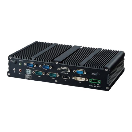
1.0 Introduction VBOX-3611-4L Illustration (MB, System) Main Board User’s Manual Page 1-3... - Page 11 1.0 Introduction System User’s Manual Page 1-4...
-
Page 12: Architecture
1.0 Introduction Architecture Principal component Specification Chip Description Intel 1. Power consumption: Core Frequency Cache i7-6600U 2.6 GHz 15 W 100°C 15 W i5-6300U 2.4 GHz 100°C 15 W i3-6100U 2.3 GHz 100°C 15 W Celeron 3955U 2.0 GHz 100°C User’s Manual Page 1-5... - Page 13 2.0 Internal Connector Specification INTERNAL CONNECTOR SPECIFICATION User’s Manual...
-
Page 14: Internal Connector
2.0 Internal Connector Specification 2.0 INTERNAL CONNECTOR MINI PCI-E Connector (MINICARD1) Connector size 2 X 26 = 52 Pin Connector type MINI PCI-E CON 9.2mmH Connector MINICARD1 location Connector pin Signal Signal definition PCIE_WAKE# 3VSB UIM_PWR_A UIM_DAT_A UIM_CLK_A UIM_RST_A MINICARD0_DIS# PCIE_RST# 3VSB USB_4N... - Page 15 2.0 Internal Connector Specification Connector map MINICARD1 User’s Manual Page 2-2...
-
Page 16: Mini Pci-E Connector (Minicard2)
2.0 Internal Connector Specification MINI PCI-E Connector (MINICARD2) Connector size 2 X 26 = 52 Pin Connector type MINI PCI-E CON 9.2mmH Connector MINICARD2 location Connector pin Signal Signal definition PCIE_WAKE# 3VSB +1.5V MINICARD2_CLKREQ# UIM_PWR_B UIM_DAT_B PCIE1_MCARD2_CLK_DN UIM_CLK_B PCIE1_MCARD2_CLK_DP UIM_RST_B MINICARD2_DIS# PCIE_RST# PCIE1_MCARD2_RX_N... - Page 17 2.0 Internal Connector Specification Connector map MINICARD2 User’s Manual Page 2-4...
-
Page 18: Mini Pci-E Connector (Minicard3)
2.0 Internal Connector Specification MINI PCI-E Connector (MINICARD3) Connector 2 X 26 = 52 Pin size Connector MINI PCI-E CON 9.2mmH type Connector MINICARD3 location Connector Signal Signal PCIE_WAKE# 3VSB definition +1.5V MINICARD3_CLKREQ# PCIE2_MCARD3_CLK_DN PCIE2_MCARD3_CLK_DP MINICARD3_DIS# PCIE_RST# PCIE2_MCARD3_RX_N 3VSB PCIE2_MCARD3_RX_P +1.5V SMB_CLK PCIE2_MCARD3_TX_N... - Page 19 2.0 Internal Connector Specification Connector MINICARD3 User’s Manual Page 2-6...
-
Page 20: Ngff Connector
2.0 Internal Connector Specification NGFF Connector Connecto 2 X 34 = 67 Pin r size Connecto NGFF _AE KEY_H:8.5mm r type Connecto NGFF1 r location Connecto Signal Signal r pin 3VSB definition USB_7P 3VSB USB_7N PCIE9_M.2_TX_0P PCIE9_M.2_TX_0N PCIE9_M.2_RX_0P PCIE9_M.2_RX_0N PCIE9_M.2_CLK_0P PCIE9_M.2_CLK_0N M.2_RST M.2_CLKREQ0#... - Page 21 2.0 Internal Connector Specification Connecto r map NGFF1 User’s Manual Page 2-8...
-
Page 22: Dio1 Jst Connector
2.0 Internal Connector Specification DIO1 JST Connector Connecto 2 X 5 = 10 Pin r size Connecto JST-2.0mm-M-180 r type Connecto DIO1 r location Connecto Signal Signal r pin DI_1 DI_2 definition DI_3 DI_4 DO_1 DO_2 DO_3 DO_4 +12V GPI: High= 5V~48V; Low= 0V GPO: 5V/100mA for each Connecto r map... -
Page 23: Com Jst Connector (Com3)
2.0 Internal Connector Specification COM JST Connector (COM3) Connecto 2 X 5 = 10 Pin r size Connecto JST-2.0mm-M-180 r type Connecto COM3 r location Connecto Signal Signal r pin COM3_DCD COM3_RXD definition COM3_TXD COM3_DTR COM3_DSR COM3_RTS COM3_CTS COM3_RI Connecto r map COM3 User’s Manual... -
Page 24: Com Jst Connector (Com4)
2.0 Internal Connector Specification COM JST Connector (COM4) Connector 2 X 5 = 10 Pin size Connector JST-2.0mm-M-180 type Connector COM4 location Connector Signal Signal COM4_DCD COM4_RXD definition COM4_TXD COM4_DTR COM4_DSR COM4_RTS COM4_CTS COM4_RI Connector COM4 User’s Manual Page 2-11... -
Page 25: Usb Jst Connector (Usb3)
2.0 Internal Connector Specification USB JST Connector (USB3) Connecto 2 X 4 = 8 Pin r size Connecto JST-2.0mm-M-180 r type Connecto USB3 r location Connecto Signal Signal r pin 5VSB 5VSB definition HubUSB_2N HubUSB_3N HubUSB_2P HubUSB_3P Connecto r map USB3 User’s Manual Page 2-12... -
Page 26: Sata Connector
2.0 Internal Connector Specification SATA Connector Connector 1 X 7 = 7 Pin size Connector SATA 1.27mm-M-180D type Connector SATA3 location Connector Signal definition SATA_TXP2 SATA_TXN2 SATA_RXN2 SATA_RXP2 Connector SATA3 User’s Manual Page 2-13... -
Page 27: Line In Jst Connector
2.0 Internal Connector Specification 2.10 LINE IN JST Connector Connecto 1X5 = 5 Pin r size Connecto JST-2.0mm-M-180 r type Connecto LINE_IN1 r location Connecto Signal Signal r pin LINE IN R LINE IN L definition LINE IN JD Connecto r map LINE IN1 User’s Manual... -
Page 28: Satapwr Jst Connector
2.0 Internal Connector Specification 2.11 SATAPWR JST Connector Connecto 1 X 2 = 2 Pin r size Connecto JST-2.0mm-M-180 r type Connecto SATAPWR1 r location Connecto Signal Signal r pin definition Connecto PIN2 r map SATA PIN1 PWR1 User’s Manual Page 2-15... -
Page 29: Vga Jst Connector
2.0 Internal Connector Specification 2.12 VGA JST Connector Connecto 2 X 8 = 16 Pin r size Connecto JST-2.0mm-M-180 r type Connecto VGA1 r location Connecto Signal Signal r pin CRT_RED CRT_GREEN definition CRT_BULE CRT_+5V CRT_SDATA CRT HSYNC CRT_VSYNC CRT_SCLK Connecto r map VGA1... -
Page 30: Ups Jst Connector
2.0 Internal Connector Specification 2.13 UPS JST Connector Connector 1 X 5 = 5 Pi n size Connector WAFER 2.54mm-M-180 type Connector UPS1 location Connector Signal +12V definition +12V Connector UPS1 User’s Manual Page 2-17... -
Page 31: Bat Power Connector
2.0 Internal Connector Specification 2.14 BAT Power Connector Connector 1 X 2 = 2 Pin size Connector JST-1.25mm-M-180 type Connector BAT1 location Connector Signal BAT +3V definition Connector PIN2 PIN1 BAT1 User’s Manual Page 2-18... -
Page 32: External Connector Specification
3.0 External Connector Specification EXTERNAL CONNECTOR SPECIFICATION User’s Manual... -
Page 33: Dp Connector
3.0 External Connector Specification 3.0 EXTERNAL CONNECTOR SPECIFICATION DP Connector Connector 20 Pin size Connector type Connector location Connector Signal Signal DP_LANE_0P definition DP_LANE_0N DP_LANE_1P DP_LANE_1N DP_LANE_2P DP_LANE_2N DP_LANE_3P DP_LANE_3N DP_AUX_EN# DP_AUXP_CLK DP_AUXN_DATA DP_HPD DP_VCC+3V Connector User’s Manual Page 3-1... -
Page 34: Dvi Connector
3.0 External Connector Specification DVI Connector Connecto 29 Pin r size Connecto DVI-I r type Connecto DVI1 r location Connecto Signal Signal r pin DVI_TX2N DVI_TX2P definition +5VSB +12V DVI_DDC_CLK DVI_DDC_DATA CRT_VSYNC DVI_TX1N DVI_TX1P Hub USB_1N Hub USB_1P DVI_VCC+5V DVI_HPD DVI_TX0N DVI_TX0P CRT_SDATA... -
Page 35: Dc Pwr Connector
3.0 External Connector Specification DC PWR Connector Connect 1 X 3 = 3 Pin or size Connect DECA 5mm-F-90D-3PIN or type Connect PWR1 location Connect Signal Signal or pin DC IN 9V~48V definitio IGNITION Connect DC IN or map IGNITION PWR1 User’s Manual Page 3-3... -
Page 36: Com Connector (Com1)
3.0 External Connector Specification COM Connector (COM1) Connecto 9 Pin r size Connecto D-SUB_9P r type Connecto COM1 r location Connecto Signal Signal r pin COM1_DCD COM1_RXD definition COM1_TXD COM1_DTR COM1_DSR COM1_RTS COM1_CTS COM1_RI# Connecto r map COM1 User’s Manual Page 3-4... -
Page 37: Com Connector (Com2)
3.0 External Connector Specification COM Connector (COM2) Connecto 9 Pin r size Connecto D-SUB_9P r type Connecto COM2 r location Connecto Signal Signal r pin COM2_DCD COM2_RXD definition COM2_TXD COM2_DTR COM2_DSR COM2_RTS COM2_CTS COM2_RI# Connecto r map COM2 User’s Manual Page 3-5... -
Page 38: Usb3.0 Connector (Usb1)
3.0 External Connector Specification USB3.0 Connector (USB1) Connecto 18 Pin r size Connecto USB3.0 Type A r type Connecto USB1 r location Connecto Signal Signal r pin 5VSB USB_0N definition USB_0P USB3_SSRX_0N USB3_SSRX_0P USB3_SSTX_0N USB3_SSTX_0P 5VSB USB_1N USB_1P USB3_SSRX_1N USB3_SSRX_1P USB3_SSTX_1N USB3_SSTX_1P Connecto... -
Page 39: Usb3.0 Connector (Usb2)
3.0 External Connector Specification USB3.0 Connector (USB2) Connecto 18 Pin r size Connecto USB3.0 Type A r type Connecto USB2 r location Connecto Signal Signal r pin 5VSB USB_2N definition USB_2P USB3_SSRX_2N USB3_SSRX_2P USB3_SSTX_2N USB3_SSTX_2P 5VSB USB_3N USB_3P USB3_SSRX_3N USB3_SSRX_3P USB3_SSTX_3N USB3_SSTX_3P Connecto... -
Page 40: Pwrout Connector
3.0 External Connector Specification PWROUT Connector Connecto 2 X 3 = 6 Pin r size Connecto ATX06PTR1-L_90D r type Connecto PWROUT1 r location Connecto Signal Signal r pin +12V +12V definition D-IN1 D-IN2 Connecto r map D-IN2 D-IN1 +12V PWROUT1 User’s Manual Page 3-8... -
Page 41: System Installation
4.0 System Installation SYSTEM INSTALLATION User’s Manual... -
Page 42: System Introduction
4.0 System Installation 4.0 SYSTEM INSTALLATION System Introduction User’s Manual Page 4-1... -
Page 43: Opening Chassis
4.0 System Installation Opening Chassis Step1. Unscrew the six screws of the Back Cover as shown in the picture. Step2. Unscrew the six screws of the Front Panel as shown in the picture. User’s Manual Page 4-2... - Page 44 4.0 System Installation Step3. Unscrew the six screws of the Rear Panel as shown in the picture. Step4. Open Top Cover as shown in the picture. User’s Manual Page 4-3...
-
Page 45: Installing Memory
4.0 System Installation Installing Memory Step1. Put Memory on this place as shown in the picture. Step2. Hold the Memory with its notch aligned with the Memory socket of the board and insert it at a 30-degree angle into the socket as shown in the picture. User’s Manual Page 4-4... - Page 46 4.0 System Installation Step3. Press down on the Memory so that the tabs of the socket lock on both sides of the module as shown in the picture. User’s Manual Page 4-5...
-
Page 47: Installing Mini Pcie Expansion Card (Pcie 1, 3G/Lte Module Only)
4.0 System Installation Installing MINI PCIe Expansion Card (PCIe 1, 3G/LTE Module only) Step 1. Put MINI PCIe Expansion Card on this place as shown in the picture. Step 2. Hold the Module with its notch aligned with the socket of the board and insert it at a 30 degree angle into the socket as shown in the picture. - Page 48 4.0 System Installation Step 3. Screw two screws to the holder as shown in the picture. Step 4. Done as shown in the picture. User’s Manual Page 4-7...
-
Page 49: Installing Mini Pcie Expansion Card (Pcie 2)
4.0 System Installation Installing MINI PCIe Expansion Card (PCIe 2) Step 1. Put MINI PCIe Expansion Card on this place as shown in the picture. Step 2. Hold the Module with its notch aligned with the socket of the board and insert it at a 30 degree angle into the socket as shown in the picture. - Page 50 4.0 System Installation Step 3. Screw one screw to the holder as shown in the picture. Step 4. Done as shown in the picture. User’s Manual Page 4-9...
-
Page 51: Installing Mini Pcie Expansion Card (Pcie 3)
4.0 System Installation Installing MINI PCIe Expansion Card (PCIe 3) Step 1. Put MINI PCIe Expansion Card on this place as shown in the picture. Step 2. Hold the Module with its notch aligned with the socket of the board and insert it at a 30 degree angle into the socket as shown in the picture. - Page 52 4.0 System Installation Step 3. Screwvone screw to the holder as shown in the picture. Step 4. Done as shown in the picture. User’s Manual Page 4-11...
-
Page 53: Installing M.2 Module
4.0 System Installation Installing M.2 Module Step 2. Put M.2 Card on this place as shown in the picture. Step 2. Hold the Module with its notch aligned with the socket of the board and insert it at a 30 degree angle into the socket as shown in the picture. User’s Manual Page 4-12... - Page 54 4.0 System Installation Step 3. Screw one screw to the holder as shown in the picture. Step 4. Done as shown in the picture. User’s Manual Page 4-13...
-
Page 55: Installing Internal Antenna Cable
4.0 System Installation Installing Internal Antenna Cable Step 1. Take the SMA Connector and Plug into IO Panel as shown in the picture. Step 2. Put the Washer into the SMA Connector as shown in the picture. User’s Manual Page 4-14... - Page 56 4.0 System Installation Step 3. Put the Oring to SMA Connector and tighten as shown in the picture. Step 4. Done as shown in the picture. User’s Manual Page 4-15...
- Page 57 4.0 System Installation Step 5. Take the Ipex Connector and press on the wifi module asshown in the picture. User’s Manual Page 4-16...
- Page 58 4.0 System Installation Step 6. Take the Ipex Connector and press on the 3G module as shown in the picture. Step 7. Take the Ipex Connector and press on the GPS module as shown in the picture. User’s Manual Page 4-17...
-
Page 59: Installing Sim Card
4.0 System Installation Installing SIM Card Step 1. Use thin stick to push the button as shown in the picture. Step 2. Take the holder away from front panel as shown in the picture. User’s Manual Page 4-18... - Page 60 4.0 System Installation Step 3. Put your SIM Card into the holder as shown in the picture. Step 4. Take the SIM card holder and Insert it into the socket as shown in the picture. Attention: Please cut the main power when you insert the SIM. Caution : The SIM card will be not detected.
-
Page 61: Installing Hdd
4.0 System Installation 4.10 Installing HDD Step 1. Put the HDD into HDD Holder as shown in the picture. Step 2. Screw two screws on both side as shown in the picture. User’s Manual Page 4-20... - Page 62 4.0 System Installation Step 3. Push the HDD Holder into the socket as shown in the picture. Step 4. Fully insert the HDD Holder into the socket until a “click” is heard as shown in the picture. User’s Manual Page 4-21...
- Page 63 4.0 System Installation Step 5. Tighten to Storage Bracket screws as shown in the picture. Step 4. Done as shown in the picture. User’s Manual Page 4-22...
-
Page 64: System Resource
5.0 System Resource SYSTEM RESOURCE User’s Manual... -
Page 65: Ignition Power Management Quick Guide
5.0 System Resource 5.0 SYSTEM RESOURCE Ignition Power Management Quick Guide Startup/shutdown conditions from the IGNITION signal: ◼ IGNITION startup signal must be valid during 3 sec. (anti-noise protection). ◼ IGNITION shutdown – IGNITION signal must be inactive during 3 Sec, then PIC controller initiate Power Button signal (OS must be set to shut down from the Power... - Page 66 ⚫ Ignition On/Off status detectable by SW ⚫ If the ignition is off and the system is still on after 3 Sec, VBOX-3611-4L will shut down automatically. ⚫ If the ignition is turned on again and the power-off delay is in progress, VBOX-3611- 4L will cancel the delay function and will continue to operate normally.
- Page 67 5.0 System Resource User’s Manual Page 5-3...
-
Page 68: Bios
6.0 BIOS BIOS User’s Manual... -
Page 69: Enter The Bios
◼ Upon boot-up, the 1st line appearing after the memory count is the BIOS version. It is usually in the format. VBOX-3611-4L Mainboard V1.0 073109 where : 1st digit refers to BIOS maker as A = AMI, W = AWARD, and P = PHOENIX 2nd - 5th digit refers to the model number. - Page 70 6.0 BIOS Control Keys Power on the computer and the system will start POST (Power On Self Test) process. When the message below appears on the screen, press (DEL) key to enter Setup. <↑> Move to the previous item <↓> Move to the next item <←>...
-
Page 71: Main
6.0 BIOS Main » System Date This setting allows you to set the system Date. The time format is <Day> <Month> <Date> <Year>. » System Time This setting allows you to set the system time. The time format is <Hour> <Minute> <Second>. -
Page 72: Advanced
6.0 BIOS Advanced CPU Configuration User’s Manual Page 6-4... - Page 73 6.0 BIOS » Limit CPUID Maximum The CPUID instruction of some newer CPUs will return a value greater than 3. The default is Disabled because this problem does not exist in the Windows series operating systems. If you are using an operating system other than Windows, this problem may occur.
- Page 74 6.0 BIOS » COM1 RS232/485 Select User’s Manual Page 6-6...
- Page 75 6.0 BIOS » COM2 RS232/485 Select User’s Manual Page 6-7...
- Page 76 6.0 BIOS » Watch Dog Function » GPIO Configuration – Power off delay time setting 0-255 User’s Manual Page 6-8...
- Page 77 6.0 BIOS » GPO 0/ 1/ 2/ 3/ Data These settings configure special GPIO data. Hardware Health Configuration These items display the current status of all monitored hardware devices/components such as voltages, temperatures and all fans' speeds. User’s Manual Page 6-9...
-
Page 78: Chipset
6.0 BIOS Chipset PCH-IO Configuration – Restore AC Power Loss User’s Manual Page 6-10... - Page 79 6.0 BIOS System Agent (SA) Configuration » Graphics Configuration User’s Manual Page 6-11...
- Page 80 6.0 BIOS User’s Manual Page 6-12...
-
Page 81: Boot
6.0 BIOS Boot » 1st/2nd/3rd Boot Device The items allow you to set the sequence of boot devices where BIOS attempts to load the disk operating system. » Try Other Boot Devices Setting the option to [Enabled] allows the system to try to boot from other device if the system fail to boot from the 1st/2nd/3rd boot device. - Page 82 6.0 BIOS » Hard Disk Drives, CD/DVD Drives, USB Drives These settings allow you to set the boot sequence of the specified devices. User’s Manual Page 6-14...
-
Page 83: Security
6.0 BIOS Security » Administrator Password Administrator Password controls access to the BIOS Setup utility. These settings allow you to set or change the administrator password. » User Password User Password controls access to the system at boot. These settings allow you to set or change the user password. -
Page 84: Exit
6.0 BIOS Exit » Save Changes and Exit Save changes to CMOS and exit the Setup Utility. » Discard Changes and Exit Abandon all changes and exit the Setup Utility. » Discard Changes Abandon all changes and continue with the Setup Utility. »... -
Page 85: Packing List
7.0 Packing List PACKING LIST User’s Manual... -
Page 86: Packing List
7.0 Packing List 7.0 PACKING LIST Packing List System Item Part Number Module Name 763611030004 VBOX-3611-4L-C1 763611030003 VBOX-3611-4L-i3 763611030002 VBOX-3611-4L-i5 763611030001 VBOX-3611-4L-i7 Accessory Picture Part Number Module Name Q’ty 370832001100 VBOX-3600 Mount Bracket 326910027661 Cabling MC421-350-02G F 90D 351103040250 Screw F Type M3*4L ISO BK...
Need help?
Do you have a question about the VBOX-3611-4L and is the answer not in the manual?
Questions and answers