
Related Manuals for Advantech UNO-2484G


Summary of Contents for Advantech UNO-2484G
- Page 1 User Manual UNO-2484G 電腦 ® Intel Core™ i Standard-Size Automation Computer with 4 x GbE, 1 x mPCIe, 1 x HDMI, 1 x DP, 4 x USB 3.0, and 4 x COM...
- Page 2 Note 2 “ ” indicates that the percentage content of the restricted substance does not exceed the percentage of reference value of presence. Note 3 The “−” indicates that the restricted substance corresponds to the exemption. UNO-2484G User Manual...
- Page 3 The documentation and the software included with this product are copyrighted 2017 by Advantech Co., Ltd. All rights are reserved. Advantech Co., Ltd. reserves the right to improve the products described in this manual at any time without notice. No part of this manual may be reproduced, copied, translated or transmitted in any form or by any means without the prior written permission of Advantech Co., Ltd.
- Page 4 UNO2484G6531904E-T, UNO2484G6531905E-T, UNO2484G6531906E-T, UNO2484G6531907E-T, UNO2484G6531908E-T, UNO2484G6531909E-T, UNO2484G6532001E-T, UNO2484G6532002E-T, UNO2484G6532003E-T, UNO2484G6532004E-T, UNO2484G6532005E-T, UNO2484G6532006E-T, UNO2484G6532007E-T, UNO2484G6532008E-T, UNO2484G6532009E-T, UNO2484G6532101E-T, UNO2484G6532102E-T, UNO2484G6532103E-T, UNO2484G6532104E-T, UNO2484G6532105E-T, UNO2484G6532106E-T, UNO2484G6532107E-T, UNO2484G6532108E-T, UNO2484G6532109E-T, UNO2484G6532201E-T, UNO2484G6532202E-T, UNO2484G6532203E-T, UNO2484G6532204E-T, UNO2484G6532205E-T, UNO2484G6532206E-T, UNO2484G6532207E-T, UNO2484G6532208E-T, UNO2484G6532209E-T, UNO2484G6331701E-T, UNO2484G6331702E-T, UNO2484G6331703E-T, UNO2484G6331704E-T, UNO2484G6331705E-T, UNO2484G6331706E-T, UNO-2484G User Manual...
- Page 5 UNO2484G6332007E-T, UNO2484G6332008E-T, UNO2484G6332009E-T, UNO2484G6332101E-T, UNO2484G6332102E-T, UNO2484G6332103E-T, UNO2484G6332104E-T, UNO2484G6332105E-T, UNO2484G6332106E-T, UNO2484G6332107E-T, UNO2484G6332108E-T, UNO2484G6332109E-T, UNO2484G6332201E-T, UNO2484G6332202E-T, UNO2484G6332203E-T, UNO2484G6332204E-T, UNO2484G6332205E-T, UNO2484G6332206E-T, UNO2484G6332207E-T, UNO2484G6332208E-T, UNO2484G6332209E-T, UNO-2484G-7731AE, UNO-2484G-7531AE, UNO-2484G-7331AE UNO-2484G-7732AE, UNO-2484G-7532AE, UNO-2484G-7332AE UNO2484G7731801E-T, UNO2484G7731802E-T, UNO2484G7731803E-T UNO2484G7731804E-T, UNO2484G7731805E-T UNO2484G7731806E-T, UNO2484G7731807E-T, UNO2484G7731808E-T UNO2484G7731809E-T, UNO2484G7731810E-T UNO2484G7731901E-T, UNO2484G7731902E-T, UNO2484G7731903E-T...
- Page 6 UNO2484G7331904E-T, UNO2484G7331905E-T UNO2484G7331906E-T, UNO2484G7331907E-T, UNO2484G7331908E-T UNO2484G7331909E-T, UNO2484G7331910E-T UNO2484G7332001E-T, UNO2484G7332002E-T, UNO2484G7332003E-T UNO2484G7332004E-T, UNO2484G7332005E-T UNO2484G7332006E-T, UNO2484G7332007E-T, UNO2484G7332008E-T UNO2484G7332009E-T, UNO2484G7332010E-T UNO2484G7332101E-T, UNO2484G7332102E-T, UNO2484G7332103E-T UNO2484G7332104E-T, UNO2484G7332105E-T UNO2484G7332106E-T, UNO2484G7332107E-T, UNO2484G7332108E-T UNO2484G7332109E-T, UNO2484G7332110E-T UNO2484G7332201E-T, UNO2484G7332202E-T, UNO2484G7332203E-T UNO2484G7332204E-T, UNO2484G7332205E-T UNO2484G7332206E-T, UNO2484G7332207E-T, UNO2484G7332208E-T UNO2484G7332209E-T, UNO2484G7332210E-T UNO-2484G User Manual...
- Page 7 Product Warranty (2 years) Advantech warrants the original purchaser that all of its products will be free from defects in materials and workmanship for two years from the date of purchase. This warranty does not apply to any products that have been repaired or altered by persons other than repair personnel authorized by Advantech, or that have been sub- ject to misuse, abuse, accident, or improper installation.
- Page 8 警告使用者 這是甲類測試產品,在居住的環境中使用時,可能會造成射頻干擾,在這種情況下, 使用者會被要求採取某些適當的對策。 Technical Support and Assistance Visit the Advantech website at www.advantech.com/support to obtain the latest product information. Contact your distributor, sales representative, or Advantech's customer service center for technical support if you need additional assistance. Please have the following information ready before you call: –...
- Page 9 In accordance with the IEC 704-1:1982 specifications, the sound pressure level at the operator position does not exceed 70 dB (A). DISCLAIMER: These instructions are provided according to IEC 704-1. Advantech disclaims all responsibility for the accuracy of any statements contained herein.
- Page 10 9. 請將電源線佈置在人們不易絆倒的位置,請勿在電源線上覆蓋任何雜物。 10. 請注意設備上所有的警告標示。 11. 如果長時間不使用設備,請拔除與電源插座的連結,避免設備被超標的電 壓波動損壞。 12. 請勿讓任何液體流入通風口,以免引起火灾或短路。 13. 請勿自行打開設備。為了確保您的安全,請透過經認證的工程師來打開設 備。 14. 如遇下列情况,請由專業人員維修: 電源線或插頭損壞; 設備內部有液體流入; 設備曾暴露在過度潮濕環境中使用; 設備無法正常工作,或您無法透過用戶手冊來正常工作; 設備摔落或損壞; 設備有明顯外觀損; 15. 請勿將設備放置在超出建議溫度範圍的環境,即不要低於 -20 ℃ (‐4 ℉) 或高於 60 ℃ (140 ℉) ,否則可能會造成設備損壞。 16. 注意:若電池更換不正確,將有爆炸危險。因此,只可以使用製造商推薦 的同一種或者同等型號的電池進行替換。請按照製造商的指示處理舊電池。 17. 根據 IEC 704‐1:1982 規定,操作員所在位置音量不可高於 70 分貝。 18. 限制區域:請勿將設備安裝於限制區域使用。 19. 免責聲明:請安全訓示符合 IEC 704‐1 要求。研華公司對其內容之準確性不 承擔任何法律責任。 UNO-2484G User Manual...
-
Page 11: Table Of Contents
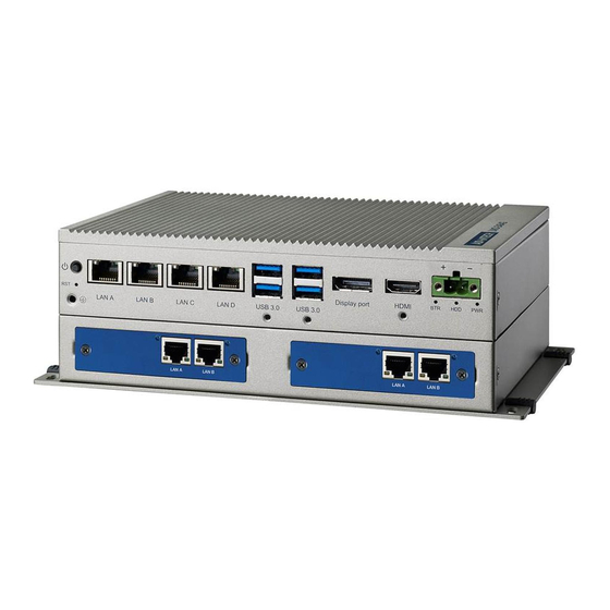
Chapter Hardware Functionality .......5 Introduction ....................6 Figure 2.1 Front panel of the UNO-2484G single-stack model..6 Figure 2.2 Front panel of the UNO2484G dual-stack model ..6 UNO-2484G Interface ................6 2.2.1 COM Port Interface (COM1, COM2, COM3, COM4) ....6 LAN: Ethernet Connector ................ - Page 12 CN15/CN53 Internal USB 2.0 Pin Header ..........33 Table A.7: CN15/CN53 Internal USB 2.0 Pin Header....33 A.10 Screw Type and Quantity for Mounting Module........33 A.11 Modifying the Serial Port Mode............... 34 A.12 BIOS Setting of TPM 2.0................. 36 UNO-2484G User Manual...
-
Page 13: Chapter 1 Overview
Chapter Overview This chapter provides an overview of UNO-2484G specifications. Introduction Safety Precautions Accessories... -
Page 14: Introduction
2484G supports one DP and one HDMI display as well as Advantech’s iDoor mod- ules. The UNO-2484G can tolerate a wide operating temperature range (-20 ~ 60 °C) and features one mini PCIe (or three additional mPCIe ports via a mini-card extender) for convenient expansion. -
Page 15: Accessories
– Display:1 x HDMI, supports 1920 x 1080 @60Hz 24bpp and 1 x DP Because UNO-2484G features a modularized design, Advantech offers both single and double-stack models. Single-stack models: UNO-2484G-6731AE/UNO-2484G-6531AE/UNO-2484G-6331AE ... - Page 16 UNO-2484G User Manual...
-
Page 17: Chapter 2 Hardware Functionality
Chapter Hardware Functionality This chapter explains how to setup the UNO-2484G’s hardware functions, including connecting peripherals and setting switches and indicators. Introduction UNO-2484G Interface LAN/Ethernet Connector Power Connector USB Connector RTC Battery Power Button/Power Manage- ment ... -
Page 18: Introduction
The UNO-2484G features four RS-232/422/485, DB9, 50 ~ 115.2 kbps. LAN: Ethernet Connector UNO-2484G is equipped with a four Gigabit LAN controller. The controller chip used is an Intel i210 Ethernet controller that is fully compliant with IEEE 802.3u 10/100/ 1000 Base-T. -
Page 19: Usb Connector
BIOS. Additionally, the provision of four USB ports complies with USB EHCI, Rev. 3.0. (Refer to Appendix A.5 for pin assignments.) RTC Battery The UNO-2484G has an RTC battery to ensure that the BIOS and system clock set- tings are retained even after brief power disconnections. ... -
Page 20: Figure 2.3 First Stack Motherboard
Figure 2.3 First stack motherboard Figure 2.4 Second stack extension board UNO-2484G User Manual... -
Page 21: Chapter 3 Initial Setup
Chapter Initial Setup This chapter explains the process for initializing the UNO-2484G. Chassis Grounding Connect the Power Supply Open/Close the Rear Cover Hard Disk Installation Extension Kit Installation... -
Page 22: Chassis Grounding
Figure 3.1 Chassis grounding connection Connect the Power Supply The UNO-2484G is intended to be supplied by a listed power adapter or DC power source rated 10 ~ 36V , 8A, and TMA 60 °C. Should you require further assistance, please contact Advantech for additional information. -
Page 23: Open/Close The Rear Cover
The rear cover can be opened in order to install a mPCIe module, mSATA SSD, or HDD, or to adjust the switch settings. Open the Rear Cover Remove the four rubber feet. Remove the two affixing screws of the rear cover. Slide to open the rear cover. UNO-2484G User Manual... - Page 24 Close the Rear Cover: Align the guide pillars between the rear cover and bracket then slide the rear cover in place and fix in position. Secure the rear cover in place using two screws. Then attach the four rubber feet. UNO-2484G User Manual...
-
Page 25: Hard Disk Installation
Hard Disk Installation 3.4.1 HDD/SSD Installation for Single-Stack UNO-2484G Remove the rear cover Remove the HDD bracket by unscrewing the four affixing screws on the HDD bracket Attach the HDD/SSD to the HDD bracket using screws UNO-2484G User Manual... - Page 26 Slide the HDD/SDD attached to the bracket into the chassis UNO-2484G User Manual...
-
Page 27: Hdd/Ssd Installation For Double-Stack Uno-2484G
Secure the HDD bracket in place using four screws Replace the rear cover. 3.4.2 HDD/SSD Installation for Double-Stack UNO-2484G Remove the rear cover. Unscrew the five affixing screws to remove the second stack extension kit UNO-2484G User Manual... - Page 28 Remove the HDD bracket by unscrewing the four screws on the HDD bracket Attach the HDD/SSD to the HDD bracket using screws UNO-2484G User Manual...
- Page 29 Slide the HDD/SDD attached to the bracket into the chassis UNO-2484G User Manual...
- Page 30 Affix the HDD bracket in place using four screws Reattach the second stack extension kit using five screws. Replace the rear cover. UNO-2484G User Manual...
-
Page 31: Hdd/Ssd Installation With Uno-2484G-S2Ae Extension Module
3.4.3 HDD/SSD Installation with UNO-2484G-S2AE Extension Module Below is the list of components provided with the UNO-2484G-S2AE extension mod- ule. Secure the second stack extension kit rear cover (5-1) in place using the screws provided (1). UNO-2484G User Manual... - Page 32 Lock PCBA Port A (3) and Port B (3) with screws (2). Secure the front cover (5-2) in place using the screws provided (1). Ensure that the HDD A port of the front cover and Port A on the PCBA are located on the same side. UNO-2484G User Manual...
- Page 33 Secure the HDD to the HDD tray (5-3) using the screws located at the internal side of the first stack layer. Insert the HDD with tray into the slot and tighten the thumb screws. UNO-2484G User Manual...
- Page 34 Align the guide pillars between the rear cover and bracket, and then slide the rear cover in place to fix in position. Secure the rear cover in place using the screws provided. Then attach the rub- ber feet. UNO-2484G User Manual...
-
Page 35: Extension Kit (Uno-2484G-Ekae) Installation
Extension Kit (UNO-2484G-EKAE) Installation Remove the rear cover Attach the second extension kit stack to the first stack. Secure the rear cover in place using the two screws provided. Then attach the four rubber feet. UNO-2484G User Manual... - Page 36 UNO-2484G User Manual...
-
Page 37: Appendix A System Settings/Pin Assignments
Appendix System Settings/Pin Assignments... -
Page 38: Cn10 Internal Gpio Pin Header
Table A.1: CN10 Internal GPIO Pin Header Signal GPIO0 GPIO1 GPIO2 GPIO3 GPIO4 GPIO5 GPIO6 GPIO7 Board Connectors and Jumpers The UNO-2484G board features several connectors and jumpers. The following sec- tions explain how to configure the UNO-2484G hardware settings. UNO-2484G User Manual... -
Page 39: Figure A.1 Connector And Jumper Locations (Front View)
CN35 AT/ATX mode switch. ON -> ATX mode, OFF -> AT mode. SW6 Clear COMS switch. Pin 1 -> normal, Pin 3 -> Clear SW7 Disable internal COM5~8, Pin (1-2) -> enable, Pin (3-4) -> disable SW8 UNO-2484G User Manual... -
Page 40: Power Connector (Pwr)
Signal Name ML_Lane 0 (p) ML_Lane 0 (n) ML_Lane 1 (p) ML_Lane 1 (n) ML_Lane 2 (p) ML_Lane2 (2) ML_Lane 3 (p) ML_Lane 3 (n) CONFIG1 CONFIG2 AUX CH (p) AUX CH (n) Hot Plug Return DP_PWR UNO-2484G User Manual... -
Page 41: Hdmi Display Connector
TMDS Data2 Shield TMDS Data2- TMDS Data1+ TMDS Data1 Shield TMDS Data1- TMDS Data0+ TMDS Data0 Shield TMDS Data0- TMDS Clock+ TMDS Clock Shield TMDS Clock- Reserved DDC/CEC/HEC Ground +5 V Power (max. 50 mA) Hot Plug Detect UNO-2484G User Manual... -
Page 42: Com1/Com2/Com3/Com4 Rs232/422/485 Connector
COM1/COM2/COM3/COM4 RS232/422/485 Connector RS232 RS422 RS485 UNO-2484G User Manual... -
Page 43: Mini Pcie Slot (Minipcie)
Note 1: +3.3V aux is suspend power; power out to device +3.3V/1.1A Note 2: +3.3V is core power Note 3: +1.5V is core power; power out to device +1.5V/0.5A UNO-2484G User Manual... -
Page 44: Lan Rj45 Connector
1000BASE-T: In MDI and in MDI-X configuration, MDI[2]+/- corresponds to BI_DC+/- and MDI[3]+/- corre- MDI2- sponds to BI_DD+/-. 100BASE-TX: Unused. MDI3+ 10BASE-T: Unused. MDI3- Left LED Right LED 10Link 100Link 1000 Link Active Orange Green Green UNO-2484G User Manual... -
Page 45: A.9 Cn15/Cn53 Internal Usb 2.0 Pin Header
CN15/CN53 Internal USB 2.0 Pin Header Table A.7: CN15/CN53 Internal USB 2.0 Pin Header Signal USB1- USB2- USB1+ USB2+ A.10 Screw Type and Quantity for Mounting Module UNO-2484G User Manual... -
Page 46: A.11 Modifying The Serial Port Mode
The default setting for the serial ports is RS-232 mode. The setting can be configured to RS-422 or RS-485 modes by following the instructions below. Power on the UNO-2484G device and press "Delete" to enter the BIOS configu- ration menu. - Page 47 Select “COM1 mode” and choose from “RS232 mode”, “RS422 mode”, or “RS485 mode”. UNO-2484G User Manual...
-
Page 48: A.12 Bios Setting Of Tpm 2.0
The UNO-2484G series supports TPM2.0 function. This function can be enabled or disabled in the BIOS configuration menu by following the instructions below. Power on the UNO-2484G device and press “Delete” to enter the BIOS configu- ration menu. Select “Advanced”=> “Trusted Computing”. - Page 49 Choose “Enabled” or “Disabled” to enable/disable TPM2.0 function in the BIOS menu. UNO-2484G User Manual...
- Page 50 UNO-2484G User Manual...
- Page 51 UNO-2484G User Manual...
- Page 52 No part of this publication may be reproduced in any form or by any means, such as electronically, by photocopying, recording, or otherwise, without prior written permission from the publisher. All brand and product names are trademarks or registered trademarks of their respective companies. © Advantech Co., Ltd. 2017...
Need help?
Do you have a question about the UNO-2484G and is the answer not in the manual?
Questions and answers