
Related Manuals for Advantech UNO-1372GH


Summary of Contents for Advantech UNO-1372GH
- Page 1 User Manual UNO-1372G/1372GH Embedded Automation ® Computer with Intel Atom Quad-Core Processor, 3 x GbE, 2 x mPCIe, 1 mSATA, 2xCOM, 8xDIO, 3xUSB, HDMI/VGA...
- Page 2 限用物質含有情況標示聲明書 UNO-1372G 系列 設備名稱: 型號 (型式) : 電腦 Equipment name Type designation (Type) ( 系列型號參見說明書 ) 限用物質及其化學符號 Restricted substances and its chemical symbols 六價鉻 多溴聯苯 多溴二苯醚 單元 Unit 汞 鎘 Hexavalent Polybrominated Polybrominated 鉛 Lead Mercury Cadmium chromium biphenyls diphenyl ethers (Pb) (Hg) (Cd)
- Page 3 No part of this manual may be reproduced, copied, translated or transmitted in any form or by any means without the prior written permission of Advantech Co., Ltd. Information provided in this manual is intended to be accurate and reliable. How- ever, Advantech Co., Ltd.
- Page 4 Because of Advantech’s high quality-control standards and rigorous testing, most of our customers never need to use our repair service. If an Advantech product is defec- tive, it will be repaired or replaced at no charge during the warranty period. For out- of-warranty repairs, you will be billed according to the cost of replacement materials, service time and freight.
- Page 5 This product has passed the CE test for environmental specifications when shielded cables are used for external wiring. We recommend the use of shielded cables. This kind of cable is available from Advantech. Please contact your local supplier for ordering information.
- Page 6 The sound pressure level at the operator's position according to IEC 704-1:1982 is no more than 70 dB (A). DISCLAIMER: This set of instructions is given according to IEC 704-1. Advantech disclaims all responsibility for the accuracy of any statements contained herein.
- Page 7 安全指示 請仔細閱讀此安全操作說明。 請妥善保存此用戶手冊供日後參考。 用濕抹布清洗設備前,請從插座拔下電源線。請不要使用液體或去汙噴霧劑清洗 設備。 對於使用電源線的設備,設備周圍必須有容易接觸到的電源插座。 請不要在潮濕環境中使用設備。 請在安裝前確保設備放置在可靠的平面上,意外跌落可能會導致設備損壞。 設備外殼的開口是用於空氣對流,從而防止設備過熱。請勿覆蓋開孔。 當您連接設備到電源插座上前,請確認電源插座的電壓是否符合要求。 請將電源線佈置在人們不易絆到的位置,並不要在電源線上覆蓋任何雜物。 請注意設備上的所有警告和注意標語。 如果長時間不使用設備,請將其同電源插座斷開,避免設備被超標的電壓波動損 壞。 請不要讓任何液體流入通風口,以免引起火災或者短路。 請不要自行打開設備。為了確保您的安全,請由經過認證的工程師來打開設備。 如遇下列情況,請由專業人員來維修: 電源線或者插頭損壞; 設備內部有液體流入; 設備曾暴露在過於潮濕的環境中使用; 設備無法正常工作,或您無法通過用戶手冊來使其正常工作; 設備跌落或者損壞; 設備有明顯的外觀破損。 請不要把設備放置在超出我們建議的溫度範圍的環境,即不要低於 0°C (32°F)或高於 40°C (104°F) ,否則可能會損壞設備。 注意:若電池放置不正確,將有爆炸的危險。因此,只可以使用製造商推薦的同 一種或者同等型號的電池進行替換。請按照製造商的指示處理舊電池。 根據 IEC 704-1:1982 的規定,操作員所在位置的聲壓級不可高於 70dB(A)。 限制區域:請勿將設備安裝於限制區域使用。...
- Page 8 UNO-1372G User Manual viii...
-
Page 9: Table Of Contents
Contents Chapter Overview ..........1 Introduction ....................2 Safety Precautions..................2 Accessories....................3 Chapter Hardware Functionality ...... 5 Introduction ....................6 Figure 2.1 Front of UNO-1372G/ 1372GH........6 Figure 2.2 Top of UNO-1372G/ 1372GH........7 2.1.1 System Hardware ................. 7 Serial Interface (COM1~COM2) ............... - Page 10 Table A.3: RS-232 Serial Port Pin Assignments......25 RS-422/485 Serial Port (COM2) ............. 25 Table A.4: RS-422/485 Serial Port Pin Assignments....25 Power Connector (PWR) ................ 26 Table A.5: Power connector pin assignments ......26 USB Connector ..................26 Table A.6: USB 2.0 Connector Pin Assignments....... 26 HDMI Display Connector ................
-
Page 11: Chapter 1 Overview
Chapter Overview This chapter provides an overview of the products specifications. Sections include: Introduction Safety precautions Accessories... -
Page 12: Introduction
Introduction The UNO-1372G is an embedded Application Ready Platform (ARP) that can shorten development time and offers multiple networking interfaces to fulfill the extensive needs of different projects. The UNO-1372G includes Intel's latest Intel Atom technology and provides multiple interfaces including up to two serial ports, three GbE LAN and three USB ports. The UNO-1372G supports two display types, HDMI and VGA for various high resolu- tion requirements. -
Page 13: Accessories
4 x PCS screws for wall mounting bracket 3 x PCS screws for DIN-Rail Bracket Driver DVD Warranty card Lockable I/O kit (only in UNO-1372GH-E3AE) If anything is missing or damaged, contact your distributor or sales representative immediately. UNO-1372G User Manual... - Page 14 UNO-1372G User Manual...
-
Page 15: Chapter 2 Hardware Functionality
Chapter Hardware Functionality This chapter shows how to setup the product’s hardware functions, including connecting peripherals, setting switches and indicators. Sections include: Introduction Serial Interface LAN / Ethernet Connector Power Connector USB Connector Display Connector ... -
Page 16: Introduction
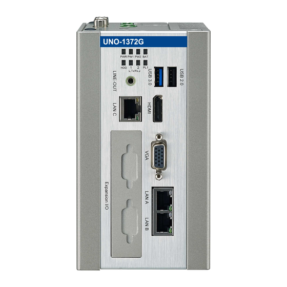
Introduction The following figures show the connectors on the product. The following sections give you information about each peripheral. Figure 2.1 Front of UNO-1372G/ 1372GH UNO-1372G User Manual... -
Page 17: System Hardware
Figure 2.2 Top of UNO-1372G/ 1372GH 2.1.1 System Hardware CPU: Intel Atom E3845 1.91GHz, 2MB L2 Cache Memory: – 4G DDR3L SDRAM built-in, – Transcend/AQD-SD3L4GN16-SG 4GB Storage: One drive bay for SATA 2.5" HDD (Compatible with 9.5mm high HDDs) ... -
Page 18: Serial Interface (Com1~Com2)
Serial Interface (COM1~COM2) The UNO-1372G offers one standard RS-232 and RS-422/485 (with cable) serial communication inter-face ports: COM1 ~ COM2. The IRQ and I/O address range are listed below: COM1: 3F8h, IRQ4 COM2: 2F8h, IRQ3 2.2.1 RS-232 Interface (COM 1) The UNO-1372G offers one RS-232 serial communication interface ports: COM1. -
Page 19: Rtc Battery
RTC Battery The RTC Battery to ensures the setting in BIOS and system clock can be kept, even with power disconnected for a short time. Type: BR2032 (Using CR2032 is NOT recommended) Output Voltage: 3 V Location: Top side removable cover named RTC BTR ... -
Page 20: Pci Express Mini Card Socket
2.10 PCI Express Mini Card Socket There are three sockets for full size PCI Express mini cards. The first interface (CN16) on bottom board is for mSATA and the second (CN8) interface is mainly tar- get to support iDoor technology/module for diversified application such as isolated COM port, Profibus, WLAN GPRS, 3G, MRAM and soon. -
Page 21: Audio Jack
2.14 Audio Jack This product provides one Line-out port for local alarm functions. 2.15 LED Indicators There are eight LEDs to indicate the status of the system power, power input 1, power input 2, RTC battery, storage read/write, COM1~2 transmit/receive and PL1 for user’s configurations. - Page 22 Figure 2.4 Wet Contact Wiring Figure 2.5 Dry Contact Wiring UNO-1372G User Manual...
-
Page 23: Chapter 3 Initial Setup
Chapter Initial Setup This chapter introduces how to initialize the UNO-1372G. Sections include: Chassis Grounding Inserting a mSATA Installing a wireless LAN card and Antenna Installing iDoor expansion kit Installing a Hard Disk Connecting Power ... -
Page 24: Chassis Grounding
Chassis Grounding The UNO-1372G provides good EMI protection and a stable grounding base. There is an easy-to-connect chassis grounding point to use. Figure 3.1 Chassis Grounding Connection Please note that the system ground and chassis ground are separated. Inserting a mSATA Remove the power cord. -
Page 25: Installing A Wireless Lan Card And Antenna (Optional)
Installing a Wireless LAN Card and Antenna (optional) Contact Advantech to prepare the following optional kit: Rear Panel for Antenna The internal cable: 1750006043 (15cm) Wireless Module (PCI Express mini card) One of the suggested module is EWM-W151H01E which is a verified Wireless IEEE 802.11b/g/n module... - Page 26 Antenna Select the necessary specification according to your application. One of the suggested antenna is 1750002842. Then follow the below steps for the installation: Unscrew the left cover and open it. Remove the hole(s) on the top panel for antenna installation. Install the internal cable 1750006043 (15cm) on the top panel.
-
Page 27: Installing A Hard Disk
Installing a Hard Disk The procedure for installing a hard disk into the UNO-1372G is below. Follow these steps carefully. Note the system is not compatible with +12V HDD. Use an HDD with lower power input. Remove the power cord. Unscrew the four screws from the left cover. -
Page 28: Bios Setup
Screw the left cover with four screws. BIOS Setup Press “F2” in the boot-up screen to enter the BIOS setup utility. Follow the instruc- tions on the screen to do the necessary settings. Note that you can try to “Restore Defaults” from the BIOS Setup manual if the UNO- 1372G does not work properly. -
Page 29: Din Rail Kit Assembly
Din Rail Kit Assembly The UNO-1372G supports Din-Rail and wall mounting. The assembly instructions are below. b. horizontal Din-Rail a. vertical Din-Rail c. wall mount (left side) d. wall mount (back side) UNO-1372G User Manual... -
Page 30: Connecting Power
Connecting Power Connect the UNO-1372G to a 9~36 V power source. The power source can either be from a power adapter or an in-house power source. UNO-1372G User Manual... -
Page 31: System Settings And Pin Assignments
Appendix System Settings and Pin Assignments... -
Page 32: System I/O Address And Interrupt Assignment
System I/O Address and Interrupt Assignment Table A.1: Interrupt Assignments Interrupt No. Interrupt Source Parity Error Detected IRQ 0 Interval timer IRQ 1 Keyboard IRQ 2 Interrupt from controller 2 (cascade) IRQ 3 COM 2 IRQ 4 COM 1 IRQ 8 Real-time clock IRQ 9 Microsoft ACPI-Compliant System... -
Page 33: Board Connectors And Jumpers
Board Connectors and Jumpers There are several connectors and jumpers on the inside board. The following sec- tions tell you how to configure the hardware setting. Figure A.1 shows the locations the connectors and jumpers. Figure A.1 Connector & Jumper Locations (front) Table A.2: Connectors and Jumpers Label Function... - Page 34 SW7: Digital Input Input Channels: 3 – Input Voltage (Wet Contact) Logic 0: 0~3 VDC (switch to 1 and 3) Logic 1: 10 ~ 30 VDC – Input Voltage (Dry Contact) Logic 0: Open (switch to 2 and 4) Logic 1: Shorted to GND –...
-
Page 35: Rs-232 Standard Serial Port (Com1)
RS-232 Standard Serial Port (COM1) Table A.3: RS-232 Serial Port Pin Assignments Pin Name RS-422/485 Serial Port (COM2) Table A.4: RS-422/485 Serial Port Pin Assignments RS-422 RS-485 Data- Data+ UNO-1372G User Manual... - Page 36 Power Connector (PWR) Table A.5: Power connector pin assignments Signal Name 1 V1+ 9~36 V Input 1 2 V2+ 9~36 V Input 2 3 V- Power Ground 4 GND Chassis Ground USB Connector Table A.6: USB 2.0 Connector Pin Assignments Signal Name Cable Color DATA-...
- Page 37 HDMI Display Connector Table A.7: HDMI Adaptor Cable Pin Assignment Signal Name TMDS Data2+ TMDS Data2 Shield TMDS Data2- TMDS Data1+ TMDS Data1 Shield TMDS Data1- TMDS Data0+ TMDS Data0 Shield TMDS Data0- TMDS Clock+ TMDS Clock Shield TMDS Clock- Reserved DDC/CEC/HEC Ground +5 V Power (max 50 mA)
- Page 38 No part of this publication may be reproduced in any form or by any means, electronic, photocopying, recording or otherwise, without prior written permis- sion of the publisher. All brand and product names are trademarks or registered trademarks of their respective companies. © Advantech Co., Ltd. 2017...
Need help?
Do you have a question about the UNO-1372GH and is the answer not in the manual?
Questions and answers