
Subscribe to Our Youtube Channel
Related Manuals for Advantech UNO-3272G Series


Summary of Contents for Advantech UNO-3272G Series
- Page 1 User Manual UNO-3272G 電腦 Intel® Celeron J1900 processors Embedded Automation Computer, with PCIe/PCI Extension slots...
- Page 2 No part of this manual may be reproduced, copied, translated or transmitted in any form or by any means without the prior written permission of Advantech Co., Ltd. Information provided in this manual is intended to be accurate and reliable. How- ever, Advantech Co., Ltd.
- Page 3 Because of Advantech’s high quality-control standards and rigorous testing, most of our customers never need to use our repair service. If an Advantech product is defec- tive, it will be repaired or replaced at no charge during the warranty period. For out- of-warranty repairs, you will be billed according to the cost of replacement materials, service time and freight.
- Page 4 Technical Support and Assistance Visit the Advantech web site at http://support.advantech.com where you can find the latest information about the product. Contact your distributor, sales representative, or Advantech's customer service center for technical support if you need additional assistance. Please have the following information ready before you call: –...
- Page 5 The sound pressure level at the operator's position according to IEC 704-1:1982 is no more than 70 dB (A). DISCLAIMER: This set of instructions is given according to IEC 704-1. Advantech disclaims all responsibility for the accuracy of any statements contained herein.
- Page 6 Consignes de sécurité Lire attentivement les instructions de sécurité. Conserver ce manuel pour utilisation ultérieure, Débranchez cet équipement de toute prise secteur avant de le nettoyer. Utilisez seulement un chiffon humide. N'utilisez pas de détergent liquide ou pulvérisé pour le nettoyage. Gardez cet équipement à...
- Page 7 安全指示 請仔細閱讀此安全操作說明。 請妥善保存此用戶手冊供日後參考。 用濕抹布清洗設備前,請確認拔除電源線。請勿使用液體或去污噴霧劑清洗設 備。 對於使用電源線的設備,設備周圍必須有容易接觸到的電源插座。 請勿在潮濕環境中試用設備。 請在安裝前確保設備放置在可靠的平面上,意外摔落可能會導致設備損壞。 設備機殼的開孔適用於空氣對,從而防止設備過熱。請勿覆蓋開孔。 當您連接設備到電源插座前,請確認電源插座的電壓符合要求。 請將電源線佈置在人們不易絆倒的位置,請勿在電源線上覆蓋任何雜物。 請注意設備上所有的警告標示。 如果長時間不使用設備,請拔除與電源插座的連結,避免設備被超標的電壓波動 損壞。 請勿讓任何液體流入通風口,以免引起火灾或短路。 請勿自行打開設備。為了確保您的安全,請透過經認證的工程師來打開設備。 如遇下列情况,請由專業人員維修: 電源線或插頭損壞; 設備內部有液體流入; 設備曾暴露在過度潮濕環境中使用; 設備無法正常工作,或您無法透過用戶手冊來正常工作; 設備摔落或損壞; 設備有明顯外觀損; 請勿將設備放置在超出建議溫度範圍的環境,即不要低於 ‐20 ℃ (‐4 ℉) 或高於 60 (140 ℉) ,否則可能會造成設備損壞。 ℃ 注意:若電池更換不正確,將有爆炸危險。因此,只可以使用製造商推薦的同一...
- Page 8 Warnings, Cautions and Notes Warning! Warnings indicate conditions, which if not observed, can cause personal injury! Caution! Cautions are included to help you avoid damaging hardware or losing data. e.g. There is a danger of a new battery exploding if it is incorrectly installed. Do not attempt to recharge, force open, or heat the battery.
-
Page 9: Table Of Contents
CONTENTS Chapter Overview..........1 Introduction ....................2 Hardware Specifications ................2 1.2.1 General ..................2 1.2.2 Display ..................2 1.2.3 Ethernet ..................2 Chipset ...................... 3 1.3.1 Functional specification..............3 Mechanical Specifications................. 4 1.4.1 Dimensions ................... 4 Figure 1.1 Dimensions..............4 1.4.2 Weight................... - Page 10 Figure 2.11VGA Connector ............16 Table 2.11: VGA Connector Pin Assignments ......16 Figure 2.12HDMI Connector............16 Table 2.12: HDMI Connector Pin Assignments......16 Figure 2.13Power Connector............17 Table 2.13: Pin Assignments for Power Connector Pin Header.. 17 Table 2.14: DI/ DO Pin Assignments........... 17 Table 2.15: DI/DO switch ............
-
Page 11: Chapter 1 Overview
Chapter Overview This chapter provides an overview of UNO-3272G' specifications. Sections include: Introduction Hardware specification Chassis dimensions Accessories... -
Page 12: Introduction
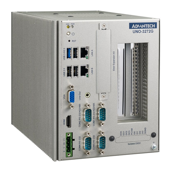
Introduction Advantech Embedded Automation PC UNO-3272G models are configured with Intel® Celeron® J1900 2.0GHz processor and 4G RAM. It supports two PCI or PCI express slots, which can fulfill extensive requirements in various applications. The UNO-3272G provide a rich array of interfaces, including 4 x USB, 2 x GigaLAN,... -
Page 13: Chipset
Chipset 1.3.1 Functional specification 1.3.1.1 Processor Processor Intel® Celeron® J1900 2.0GHz processor 1.3.1.2 Chipset Supports DDR3L 1333 MHz (without ECC) Memory SODIMM Socket – 260-pin SODIMM socket*2 (up to 8 GB) Intel® HD Graphics for Intel Atom® Processor Z3700 Series ... -
Page 14: Mechanical Specifications
Mechanical Specifications 1.4.1 Dimensions Figure 1.1 Dimensions 1.4.2 Weight 2.6 kg Power Requirements 1.5.1 System power DC 10-36V 1.5.2 RTC battery BR2032 3 V/190 mAh Environment Specification 1.6.1 Operating temperature -20 ~ 60 °C with 0.7m/sec air flow: with 1x Industrial SSD without PCI/PCIe expan- sion boards 1.6.2 System safety certification test temperature... -
Page 15: Vibration During Operation
1.6.5 Vibration during operation When system is equipped with SSD only: 2 Grms, IEC 60068-2-64, random, 5 ~ 500 Hz, 1 Oct/min., 1 hr/axis, x,y,z 3 axes. When system is equipped with 2.5-inch HDD: 0.5 Grms, IEC 60068-2-64, ran- dom, 5 ~ 500 Hz, 1 Oct/min., 1 hr/axis, x,y,z 3 axes. - Page 16 UNO-3272G User Manual...
-
Page 17: Chapter 2 H/W Installation
Chapter H/W Installation This chapter introduces external IO and the installation of UNO- 3272G hardware. -
Page 18: Introduction
Introduction The following sections show the internal jumper settings and the external connectors and pin assignments. Figure 2.1 Motherboard Connector and jumper locations (top side) UNO-3272G User Manual... - Page 19 Figure 2.2 Motherboard Connector and jumper locations (rear side) Table 2.1: Motherboard Connector Location Function Location Function LANA+USB3.0/2.0 CN16 Internal Power Switch/Reset LANB+USB2.0 CN18 CN65 Power Input Internal USB2.0 MPCIE1 Mini PCIe SATA Power SLOT1 PCIE Slot SIM Holder Power/SATA status LED CN10 COM1/2/3/4+Audio Power Switch...
- Page 20 Figure 2.3 PCIe card connector locations Table 2.2: PCIE Connector Location Function 12V Power Output 5V&12V Power Output PCIE2 PCIE1 Figure 2.4 COM card connector locations UNO-3272G User Manual...
-
Page 21: Jumpers
Table 2.3: COM Connector Location Function COM1/COM2 COM3COM4 MIC IN LINE Out Jumpers Configure the UNO-3272G to match the needs of your application by setting jumpers. To close a jumper, you connect the pins with the clip. To open a jumper, you remove the clip. -
Page 22: Connectors
2.2.1.1 Clear CMOS UNO-3272G mainboard contains a jumper that can erase CMOS data and reset the system BIOS information. Normally this jumper should be set with pins 1-2 closed. If you want to reset the CMOS data, set CMOS1 to 2-3 closed for just a few seconds, and then move the jumper back to 1-2 closed. - Page 23 2.3.1.1 COM connector UNO-3272G provides four 9-pin D-sub connectors, two of which offer RS-232/422/ 485 and the other two offer RS-232 serial communication interface ports. Default set- ting is RS-232, but this can be modified by BIOS setting. You can find detailed setting methods in Chapter 3.
- Page 24 2.3.1.2 Ethernet connector (LAN) UNO-3272G is equipped with two Ethernet controllers that are fully compliant with IEEE 802.3u 10/100/1000 Mbps CSMA/CD standards. LANA &LANB are equipped with Intel i211. The Ethernet port provides a standard RJ45 jack connector with LED indicators on the front side to show its Active/Link status and Speed status.
- Page 25 2.3.1.3 Audio connector UNO-3272G has only one stereo audio ports with phone jack connectors- Line_Out. The audio chip is controlled by ACL888-VD2, and it's compliant with AZALIA stan- dard. Figure 2.8 Audio Connector Table 2.8: Audio Connector Pin Assignments Audio signal Name Line_out 2.3.1.4 USB 3.0 connector...
- Page 26 2.3.1.5 VGA connector The UNO-3272G provides a high resolution VGA interface with a 15-pin D-sub con- nector to support a VGA CRT monitor. It supports display resolution of up to1920 x 1080 @ 60 Hz. Figure 2.11 VGA Connector Table 2.11: VGA Connector Pin Assignments Signal Name Signal Name Green...
- Page 27 This product is intended to be supplied by a UL Listed DC Power Source, rated 10-36Vdc, 6.5-1.8A and Tma 40 degree C, if need further assis- tance, please contact Advantech for further information (Ensure to connect the power cord to a socket-outlet with earthing connection).
- Page 28 Table 2.14: DI/ DO Pin Assignments Isolated digital input Isolated digital input Isolated digital input Isolated digital input DGND External common of IDI0~3 Table 2.15: DI/DO switch Dry Contact Wet Contact Default: Dry contact Isolated Digital Input Each of the 4 isolated digital input channels accept voltages from 0 to 30 V.
- Page 29 Figure 2.15 Isolated DI Wet connection Isolated Digital Output If the external voltage source (5~40 V) is connected to each isolated output channel (IDO) and its isolated digital output turns on (200 mA max./ ch), the card's current will sink from the external voltage source. The following figure shows how to connect an external output load to the card's isolated outputs.
-
Page 30: Internal I/O Connectors
2.3.2 Internal I/O Connectors Table 2.16: PCIE Connector Pin Assignments FAN1 Signal Name Signal Name Signal Name +V12 +V12 +V12 +V12 Installation 2.4.1 HDD installation UNO-3272G supports 1 HDD/ SDD installation. The following steps demonstrate how to install 2.5” storage. Remove 8 screws from top and side cover of UNO UNO-3272G User Manual... - Page 31 Remove the 4 screws on rear cover of UNO. Take off the HDD/SSD tray from rear cover inside. UNO-3272G User Manual...
- Page 32 Secure the HDD with 4 pcs reserved screws in the accessory package. Slide down the tray and replace all the screws and put the cover back. UNO-3272G User Manual...
-
Page 33: Memory & M.2 Storage Installation
2.4.2 Memory & M.2 storage installation UNO-3272G has default build-in 4G RAM, but can support up to 8GB by adding addi- tional 4G Memory; UNO-3272G also provides M.2 B-key storage with up to 512 GB. Following steps demonstrate how to install additional RAM and M.2 Storage. Remove the 8 screws from the top and side cover of UNO, install the RAM mod- ule and M.2 storage as below: Replace all screws and put the cover back. -
Page 34: Idoor Installation
2.4.3 iDOOR Installation UNO-3272G supports 1 x iDOOR expansion by utilizing the mPCIe interface. The fol- lowing steps demonstrate how to install the iDOOR module with the mPCIe card. Remove 8 screws from top and side cover of UNO, install the mPCIe module as below: Remove iDOOR screws on front panel and take off the iDOOR plate from UNO. -
Page 35: Di/O Card Installation (Optional)
2.4.4 DI/O card Installation (Optional) UNO-3272G allows 4 x DI/DO by ordering additional DIO cards (PN: UNO-3000- DIOAE). Follow these steps to demonstrate how to install a DI/O card. Remove the rubber and punch out from the reserved DI/O holes. UNO-3272G User Manual... - Page 36 Fix the DI/O card by replacing the 2 screws on accessory package. Connect DI/O cable as below (Motherboard: CN13). UNO-3272G User Manual...
-
Page 37: Pci/ Pcie Installation (Optional)
2.4.5 PCI/ PCIe Installation (Optional) UNO-3272G provides 2 x PCIex1 expansion slots for add-on cards. Follow the steps for how to install add-on cards. Remove 8 screws from the top and side cover of UNO as well as the PCI/PCIe bracket. -
Page 38: Fan-Kit Installation (Optional)
2.4.6 FAN-kit Installation (Optional) The following steps demonstrate how to install an optional fan kit (PN: UNO-3000- FANAE) Remove 8 screws from the top and side cover of UNO and take out the filter. Remove 4 screws on the top cover. UNO-3272G User Manual... - Page 39 Fix the fan-kit by replacing the 4 screws. Connect power cable as below. UNO-3272G User Manual...
-
Page 40: Riser Card (Change) Installation
2.4.7 Riser card (change) Installation UNO-3272G provides other riser cards (2 x PCI) for different applications. Pull out the current riser card and remove the copper pillars from the chassis. Plug in the new riser card then replace the 5 screws. UNO-3272G User Manual... -
Page 41: Mounting Kit Installation (Optional)
2.4.8 Mounting kit Installation (Optional) UNO-3272G supports wall mount and stand mount. Optional mounts (PN:UNO-3000- WMKAE). 2.4.8.1 Wall Mounting Remove the screws from UNO chassis then fix the mounting kit on UNO using the same screws (M4*5L*4 Pcs). Install UNO-3272G on the wall by replacing the 4 screws. UNO-3272G User Manual... - Page 42 2.4.8.2 Stand Mounting Remove the screws from the UNO chassis then fix the mounting kit on UNO using same screws. Install UNO-3272G by replacing the 4 screws UNO-3272G User Manual...
-
Page 43: Chapter 3 Ami Bios Setup
Chapter AMI BIOS Setup This chapter introduces how to set BIOS configuration data. -
Page 44: Introduction
Introduction With the AMI BIOS Setup program, you can modify BIOS settings and control the special features of your computer. The Setup program uses a number of menus for making changes and turning special features on or off. This chapter describes the basic navigation of the UNO-3272G setup screens. -
Page 45: Advanced Bios Features Setup
The Main BIOS setup screen has two main frames. The left frame displays all the options that can be configured. Grayed-out options cannot be configured; options in blue can. The right frame displays the key legend. Above the key legend is an area reserved for a text message. When an option is selected in the left frame, it is highlighted in white. - Page 46 3.2.2.1 Trusted Computing Security Device Support This item allows users to enable or disable "Security Device Support". 3.2.2.2 ACPI Settings Enable ACPI Auto Configuration This item allows users to enable or disable “ACPI Auto Configuration”. UNO-3272G User Manual...
- Page 47 Enable Hibernation This item allows users to enable or disable “Hibernation”. ACPI Sleep State This item allows users to set ACPI mode S3 (Suspend to RAM) or to Disable “ACPI Sleep State”. Lock Legacy Resources This item allows users to enable or disable “Lock Legacy Resources” 3.2.2.3 IT8768E Super IO Configuration UNO-3272G supports 2xRS-232/422/485 &...
- Page 48 Serial Port 1 Configuration – Serial Port This item allows users to enable or disable for "Serial Port". – Change Settings This item allows users to Change Settings of Serial Ports. The default setting is "RS-232". UNO-3272G User Manual...
- Page 49 – Device Mode This item allows users to set the mode to RS-422/485. The default setting is "RS232". Serial Port 2 Configuration – Serial Port This item allows users to enable or disable for "Serial Port". – Change Settings This item allows users to change settings of serial ports.
- Page 50 Serial Port 3 Configuration – Serial Port This item allows users to enable or disable for "Serial Port". – Change Settings This item allows users to Change Settings of Serial Ports. The default setting is "Auto". Serial Port 4 Configuration –...
- Page 51 3.2.2.4 Embedded Controller Configuration iManager WatchDog IRQ This item allows users to enable or disable for "iManager WatchDog IRQ" 3.2.2.5 S5 RTC Wake Settings Wake system from S5 This item allows users to enable or disable for "Wake system from S5" UNO-3272G User Manual...
- Page 52 3.2.2.6 CPU Configuration Execute Disable Bit This item allows users to enable or disable for "Execute Disable Bit". Intel Virtualization Technology This item allows users to enable or disable for "Intel Virtualization Technology". UNO-3272G User Manual...
- Page 53 3.2.2.7 IDE Configuration 3.2.2.8 Miscellaneous Configuration OS Selection: This items allow user to set the OS mode: "Win 8.x" or "Win 7"or “WinCE 7". (If user installs Win 10 or Linux OS, set for "Win8.x") UNO-3272G User Manual...
- Page 54 3.2.2.9 LAN Controller LAN Controller This items allowed user to enable or disable for wake on LAN function 3.2.2.10 Network Stack Configuration UNO-3272G User Manual...
- Page 55 Network Stack This item allows users to enable or disable for "Network Stack" (For using UEFI PXE function, please enable this item). 3.2.2.11 CSM Configuration CSM Support This item allows users to enable or disable for "CSM Support". ...
- Page 56 3.2.2.12 USB Configuration Legacy USB Support This item allows users to enable or disable or set Auto for "Legacy USB Sup- port". XHCI Hand-off This item allows users to enable or disable "XHCI Hand-off". EHCI Hand-off This item allows users to enable or disable "EHCI Hand-off". ...
-
Page 57: Chipset
3.2.3 Chipset UNO-3272G User Manual... - Page 58 3.2.3.1 USB Configuration USB Per port control This item allows users to enable or disable for "USB Per port control". UNO-3272G User Manual...
-
Page 59: Security
3.2.3.2 PCI Express Configuration 3.2.4 Security Set Admin Password This item allows users to set "Administrator Password" if desired. UNO-3272G User Manual... -
Page 60: Boot
3.2.5 Boot Setup Prompt Timeout Number of Seconds to wait for setup activation kay. 65535 (0xFFFF) means indefinite waiting. Bootup NumLock State This item allows users to set "Bootup NumLock State" either On or Off. Quiet Boot This item allows users to disable or enable "Quiet Boot". -
Page 61: Save & Exit
3.2.6 Save & Exit Save Changes and Exit This item allows users to Save Changes and Exit. Discard Changes and Exit This item allows users to Discard Changes and Exit. UNO-3272G User Manual... - Page 62 Save Changes and Reset This item allows users to Save Changes and Reset. Discard Changes and Reset This item allows users to Discard Changes and Reset. Save Changes This item allows users to Save Changes. Discard Changes ...
- Page 63 UNO-3272G User Manual...
- Page 64 No part of this publication may be reproduced in any form or by any means, electronic, photocopying, recording or otherwise, without prior written permis- sion of the publisher. All brand and product names are trademarks or registered trademarks of their respective companies. © Advantech Co., Ltd. 2019...
Need help?
Do you have a question about the UNO-3272G Series and is the answer not in the manual?
Questions and answers