
Related Manuals for Advantech UNO-148


Summary of Contents for Advantech UNO-148
- Page 1 User Manual UNO-148 電腦 ® Intel Tiger Lake UP3 Processor Automation Computer, with 3 x LAN, 4 x COM, 3 x USB 3.2 Gen2, 1 x USB 2.0, 2 x DP 1.4, 8DI/8DO, 1 x mPCIe, 1 x M.2 B+M Key, 1 x M.2 E Key, 1 x Nano SIM Slot and...
- Page 2 No part of this manual may be reproduced, copied, translated, or transmitted in any form or by any means without the prior written permission of Advantech Co., Ltd. The information provided in this manual is intended to be accurate and reliable.
- Page 3 UNO148B33B2503-T Product Warranty (2 years) Advantech warrants the original purchaser that each of its products will be free from defects in materials and workmanship for two years from the date of purchase. This warranty does not apply to any products that have been repaired or altered by persons other than repair personnel authorized by Advantech, or products that have been subject to misuse, abuse, accident, or improper installation.
- Page 4 This product has passed the CE test for environmental specifications when shielded cables are used for external wiring. We recommend the use of shielded cables. This type of cable is available from Advantech. Please contact your local supplier for ordering information.
- Page 5 Discard used batteries according to the manufacturer’s instructions. In accordance with IEC 704-1:1982 specifications, the sound pressure level at the operator’s position does not exceed 70 dB (A). UNO-148 User Manual...
- Page 6 This equipment is not suitable for use in locations where children are likely to be present. If the equipment is used in a manner not specified by the Advantech, the protec- tion provided by the equipment may be impaired. The equipment contains no user-serviceable parts. Do not open, Return to man- ufacturer for servicing.
- Page 7 Jeter les piles usagées selon les instructions du fabricant. 安全指示 請仔細閱讀此安全操作說明。 請妥善保存此用戶手冊供日後參考。 用濕抹布清洗設備前,請確認拔除電源線。請勿使用液體或去污噴霧劑清洗設 備。 對於使用電源線的設備,設備周圍必須有容易接觸到的電源插座。 請勿在潮濕環境中試用設備。 請在安裝前確保設備放置在可靠的平面上,意外摔落可能會導致設備損壞。 設備機殼的開孔適用於空氣對,從而防止設備過熱。請勿覆蓋開孔。 當您連接設備到電源插座前,請確認電源插座的電壓符合要求。 請將電源線佈置在人們不易絆倒的位置,請勿在電源線上覆蓋任何雜物。 請注意設備上所有的警告標示。 如果長時間不使用設備,請拔除與電源插座的連結,避免設備被超標的電壓波動 損壞。 請勿讓任何液體流入通風口,以免引起火灾或短路。 請勿自行打開設備。為了確保您的安全,請透過經認證的工程師來打開設備。 如遇下列情况,請由專業人員維修: 電源線或插頭損壞; 設備內部有液體流入; 設備曾暴露在過度潮濕環境中使用; 設備無法正常工作,或您無法透過用戶手冊來正常工作; UNO-148 User Manual...
- Page 8 設備摔落或損壞; 設備有明顯外觀損; 請勿將設備放置在超出建議溫度範圍的環境,即不要低於 -40° C (-40° F)或 高於 60° C (140° F),否則可能會造成設備損壞。 注意:若電池更換不正確,將有爆炸危險。因此,只可以使用製造商推薦的同一 種或者同等型號的電池進行替換。請按照製造商的指示處理舊電池。 根據 IEC 704‐1:1982 規定,操作員所在位置音量不可高於 70 分貝。 限制區域:請勿將設備安裝於限制區域使用。 免責聲明:請安全訓示符合 IEC 704‐1 要求。研華公司對其內容之準確性不承 擔任何法律責任。 消费者若使用电源适配器供电,则应购买配套使用获得 CCC 认证并满足标准要 求的电源适配器。 UNO-148 User Manual viii...
-
Page 9: Table Of Contents
Chapter Hardware Functionality.......9 Introduction ..................... 10 Figure 2.1 Diagram of Connector Locations on UNO-148 (Top Side) ................. 10 Figure 2.2 Key Components Locations of UNO-148 (Bottom Side) Table 2.1: Key Components, Connectors on Board ....11 External I/O Connector................12 2.2.1... - Page 10 Installing mPCIE ................. 35 Din-Rail Installation ................. 36 Wireless Module Installation (Optional) ..........37 Extension Kit Installation (Optional) ............38 3.7.1 iDoor and HDD/SSD Storage Extension Kit (UNO-148-IS2EA) . 38 3.7.2 iDoor Extension Kit (UNO-148-ID1EA) ........42 3.7.3 PCIe Expansionx4 (UNO-148-P11EA) ........46 Remote Power &...
- Page 11 Table A.8: Expansion Board to Board Connector Pin Assignments A.11 TPM 2.0 BIOS Setting................64 A.12 CPU Turbo Mode BIOS Setting .............. 66 UNO-148 User Manual...
- Page 12 UNO-148 User Manual...
-
Page 13: Chapter 1 Overview
Chapter Overview This chapter overviews specifica- tions for UNO-148. Introduction Safety Precautions Accessories Hardware Specifications Dimensions... -
Page 14: Introduction
Introduction Advantech's UNO-100 series are DIN-rail integrated controller that feature a modular design for flexible configuration according to specific usage requirements. ® UNO-148 is equipped with an 11th Generation Intel Core™ i Processor (General 1.8GHz) with 8GB DDR4 RAM, and 3 x LAN, 4 x COM, 3 x USB 3.2 Gen2, 1 x USB 2.0, 8 x DI, 8 x DO and 2 x DP 1.4. -
Page 15: Packing List
Packing List Please refer to below packing list: UNO-148 (with din-rail mount) 2 x 10 PIN Plug-in block for COM port 1 x 20 PIN Plug-in block for DIO 1 x 2 PIN Plug-in for Power ... -
Page 16: System Hardware
1 x Nano SIM card slot for B-key use 1 x M.2 E-key 2230 WiFi module (PCIe/USB2.0 Signal) 1 x E-key miniPCIe (PCIe/USB2.0 Signal) Note! The M.2 B-key can support either 2242 storage (w/ SATA signal) or 3042/3052 Module (w/ USB signal). UNO-148 User Manual... -
Page 17: I/O Interfaces
(SSD) Vibration Protection Operating, IEC 60068-2-64, 0.3 Grms, random,5 ~ 500Hz, 1hr/ axis (HDD) Note! It is recommended to use 2.5" SSD under the temperature of 60° C/140° 1.4.5 Certification Certification CE, FCC, CB, UL 61010-2-201, BSMI UNO-148 User Manual... -
Page 18: Extension Kit (Optional)
UNO-148 features a modularized design. Advantech offers an optional 2nd extension kit. UNO-148-ID1EA Expansion unit (iDoor x 1) Part number UNO-148-ID1EA 2nd stack extension kit to support 1 x iDoor on UNO-148- Description ID1EA Ports 1 x iDoor Dimensions (W x D x H) -
Page 19: Dimensions
45 x 140 x 200 mm (W x D x H mm) Figure 1.1 UNO-148 Dimension 80 x 140 x 200 mm (W x D x H mm) Figure 1.2 UNO-148 Dimension (With UNO-148-IS2EA Optional Extension Kit)) UNO-148 User Manual... - Page 20 80 x 140 x 200 mm (W x D x H mm) Figure 1.3 UNO-148 Dimensions (With UNO-148-ID1EA Optional Extension Kit) Figure 1.4 UNO-148 Dimensions (With UNO-148-ID1EA Optional Extension Kit) UNO-148 User Manual...
-
Page 21: Chapter 2 Hardware Functionality
Chapter Hardware Functionality This chapter details setup instruc- tions for UNO-148’s hardware functions. It includes connecting peripherals and indicators. Introduction External I/O Connector Internal I/O Connector LED Indicators Reset Buttons Antenna Hole... -
Page 22: Introduction
Introduction The following diagram demonstrates the location of UNO-148’s motherboard’s key components and internal/external connectors. Figure 2.1 Diagram of Connector Locations on UNO-148 (Top Side) Figure 2.2 Key Components Locations of UNO-148 (Bottom Side) UNO-148 User Manual... - Page 23 COM Port Terminal Connector (RS232/422/485) CN12 Riser Connector MINI1 MiniPCIe Connector CN14 M.2 B key for 2242/3042/3052 Connector CN13 M.2 E key for 2230 Connector Internal CN15 M.2 M key for 2280 Connector DIMM2 Memory Slot DIMM1 Memory Slot UNO-148 User Manual...
-
Page 24: External I/O Connector
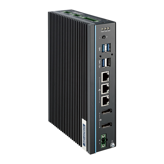
External I/O Connector 2.2.1 UNO-148 Base Unit Figure 2.3 Front Panel of UNO-148 Figure 2.4 Top View of UNO-148 UNO-148 User Manual... -
Page 25: Uno-148 Base Unit With Uno-148-Is2Ea Expansion Unit
2.2.2 UNO-148 Base Unit with UNO-148-IS2EA Expansion Unit (1 x iDoor and 1 x 2.5”SSD/HDD) Figure 2.5 Front Panel of UNO-148 Figure 2.6 Top View of UNO-148 UNO-148 User Manual... -
Page 26: Uno-148 Base Unit With Uno-148-Id1Ea Expansion Unit (Idoor X 1)
2.2.3 UNO-148 Base Unit with UNO-148-ID1EA Expansion Unit (iDoor x 1) Figure 2.7 Front Panel of UNO-148 Figure 2.8 Top View of UNO-148 UNO-148 User Manual... -
Page 27: Uno-148 Base Unit With Uno-148-P11Ea Expansion Unit (1X Pcie Expansionx4)
2.2.4 UNO-148 Base Unit with UNO-148-P11EA Expansion Unit (1x PCIe expansionx4) Figure 2.9 Front Panel of UNO-148 Figure 2.10 Top View of UNO-148 UNO-148 User Manual... -
Page 28: Power Connector
2.2.7 USB Connector UNO-148 features 4x USB ports that comply with USB EHCI, 3 for Rev. 3.2, 1 for Rev. 2.0 (Type A) specifications. The USB connectors support plug-and-play and hot- swap- ping functionality for external devices. Additionally, this can be enabled/dis- abled in the BIOS menu. -
Page 29: Com Connector
2.2.9 COM Connector UNO-148 has 4 x COM RS232/422/485 ports of terminal block type. They offer trans- mission speeds of 50 ~115.2 kbps. The default mode for both COM ports (COM1&COM2) is RS-232 Mode. Settings can be adjusted via an on-board switch (SW1). -
Page 30: Digital Input And Output
Logic 1: 0~3 V Input Voltage (Dry Contact), Configure SW3 to Setting 1 – Logic 0: Shorted to GND – Logic 1: Open Isolation Protection 2,500 V Over-voltage Protection 30 V Opto-Isolator Response 50 μs UNO-148 User Manual... - Page 31 Each of the 8 x isolated digital input channels accept voltages from 0 to 30 V. The fol- lowing figure shows how to connect an external input source to the isolated inputs of UNO- 148. Figure 2.11 Isolated DI Wet Connection Diagram Figure 2.12 Isolated DI Dry Connection Diagram UNO-148 User Manual...
-
Page 32: Internal I/O Connectors And Switches
(500 mA max./ch), the board's current will sink from the external voltage source. The following figure shows how to connect an external output load to the isolated outputs on UNO-148. Figure 2.13 Isolated DO Connection Diagram... - Page 33 Nano SIM slot Connector BAT1 RTC Battery Connector BIOS update Setting Note! *This power is from DC Power inputs. Configure the UNO-148 to match the needs of your application by setting switches, The following details the switch setting definitions: UNO-148 User Manual...
-
Page 34: Connector
BTR (RTC Battery): Red indicates a low RTC battery. Check the RTC battery. RUN (Programmable): Users can configure the LED indicator’s behavior through GPO signal controls. Green indicates under programming. 2.4.2 Reset Buttons Press the “Reset” button to initiate a hardware reset. UNO-148 User Manual... -
Page 35: Antenna Hole
This product offers two antenna mounting holes covered by pre-cut holes for users to install an antenna kit for LTE or wireless functions. Note! Please be aware of the Maximum OD value of the Antenna Hole when selecting antenna. Figure 2.16 Diagram of Maximum OD Value for Antenna Hole UNO-148 User Manual... - Page 36 UNO-148 User Manual...
-
Page 37: Chapter 3 Initial Setup
Chapter Initial Setup This chapter explains how to Ini- tialize the UNO-148. Chassis Grounding Connecting Power Storage Installation (Optional) Din-Rail Installation Wireless Module Installation (Optional) Expansion Module Installation (Optional) Remote Power/On & Reset Set- ting ... -
Page 38: Chassis Grounding
Chassis Grounding The UNO-148 provides good EMI protection and a stable grounding base. There is an easy-to-connect chassis grounding point. Figure 3.1 Chassis Grounding Connection Earth terminal shall be used 16 AWG minimum size with green and yellow conductor to connector to earth. -
Page 39: Connecting Power
This product is intended to be supplied by an approved power adapter or DC power source. This adapter is rated at 10 - 36Vdc, 7.7-1.31A and has a Tmax of 70 °C (158 °F). If you need further assistance or information, please contact Advantech. Note! It is recommended to choose a 150W adapter when selected iDoor expansion module(e.g. -
Page 40: Storage Installation (Optional)
Storage Installation (Optional) UNO-148 supports the installation of one M.2 2280 NVMe SSD. The installation is demonstrated in the following steps. 3.3.1 Installing a M.2 2280 NVMe Remove 2 screws from UNO’s back cover. UNO-148 User Manual... - Page 41 Remove the provided screws from the board. Insert the NVMe Card on the location. “CN15”. Secure it with the provided screws from Step 2. UNO-148 User Manual...
-
Page 42: Installing M.2 3042 Module
Installing M.2 3042 Module Loosen the provided screws from the board. (No need to remove the screw.) Using the 3042 bracket from the accessory bag and Insert the in the gap where the screw is loosened from Step1. UNO-148 User Manual... - Page 43 Move the 3042 bracket to the center of M.2 center and tighten the screws. Remove the provided screws from the 3042 bracket first. Insert the M.2 3042 card and tighten the screw. UNO-148 User Manual...
-
Page 44: Installing M.2 3052 Module
3.3.3 Installing M.2 3052 Module Remove the provided screws from the board. Insert the M.2 3052 to the location.”CN14”and tighten the screw. UNO-148 User Manual... -
Page 45: Installing M.2 2230 Module
Installing M.2 2230 Module Remove the provided screws from the board. UNO-148 User Manual... - Page 46 Insert the M.2 2230 to the location.”CN13”and tighten the screw. UNO-148 User Manual...
-
Page 47: Installing Mpcie
3.4.1 Installing mPCIE Remove the provided screws from the board. Insert the mPCIE to the location.”MINI1”and tighten the screw. UNO-148 User Manual... -
Page 48: Din-Rail Installation
Din-Rail Installation Install UNO-148 on the rail and secure it to the rail. Buckle inward Pull down the “Release Latch” for disassembly using a screwdriver. UNO-148 User Manual... -
Page 49: Wireless Module Installation (Optional)
Wireless Module Installation (Optional) UNO-148 supports to install WiFi iDoor/M.2 3042/M.2 3052 module. Follow the steps below for installation: Remove 2 screws from back cover of UNO. Remove the plug of antenna pre-cut hole(s) on the top panel for antenna instal- lation. -
Page 50: Extension Kit Installation (Optional)
HDD/SSD Storage Extension Kit (UNO-148-IS2EA) You can additionally install 2nd stack iDoor and external swappable 2.5" HDD/SSD Storage extension kit (PN: UNO-148-IS2EA) on UNO-148 to expand its functionality: The accessory list for iDoor extension kit (PN: UNO-148-IS2EA) 5 x M3x4L screws for extension kit installation... - Page 51 Follow the steps below for extension kit Installation: Remove M3 x4L x 2 screws from back cover of UNO-148. Remove 2 x M3 x6L pcs the screw from the extension Kit. Detach the iDoor dummy cover from the iDoor extension kit.
- Page 52 Attach the 2nd bracket (UNO-148-IS2EA) with 6 x M3x4L pcs screws to the Base Unit (UNO-148). UNO-148 User Manual...
- Page 53 Connect the mPCIe connector of iDoor module onto the board of the UNO-148, and fix it with the 2 x M2x4L pcs screw from the accessory bag of iDoor exten- sion kit. Detach the HDD/SSD bracket from 2nd stack extension kit, then fix the 2.5”...
-
Page 54: Idoor Extension Kit (Uno-148-Id1Ea)
Return the back cover and gently screw it into place. 3.7.2 iDoor Extension Kit (UNO-148-ID1EA) You can additionally install 2nd stack iDoor extension kit (PN: UNO-148-ID1EA) on UNO-148 to expand its functionality: The accessory list for iDoor extension kit (PN: UNO-148-ID1EA) - Page 55 Follow the steps below for extension kit Installation: Remove M3 x4L x 2 screws from back cover of UNO-148. Detach the iDoor dummy cover from the iDoor extension kit. UNO-148 User Manual...
- Page 56 Attach the 2nd bracket (UNO-148-ID1EA) with 6 x M3x4L pcs screws to the Base Unit (UNO-148). UNO-148 User Manual...
- Page 57 Connect the mPCIe connector of iDoor module onto the board of the UNO-148, and fix it with the 2 x M3x4L pcs screw from the accessory bag of iDoor exten- sion kit. Return the back cover and gently screw it into place.
-
Page 58: Pcie Expansionx4 (Uno-148-P11Ea)
3.7.3 PCIe Expansionx4 (UNO-148-P11EA) You can additionally install 2nd stack expansionx4 kit (PN: UNO-148-P11EA) on UNO-148 to expand its functionality: The accessory list for iDoor extension kit (PN: UNO-148-P11EA) 8x M3x4L screws for extension kit installation UNO-148 User Manual... - Page 59 Follow the steps below for extension kit Installation: Remove M3 x4L x 2 screws from back cover of UNO-148. UNO-148 User Manual...
- Page 60 Attach the 2nd bracket (UNO-148-P11EA) with 6 x M3x4L pcs screws to the Base Unit (UNO-148). UNO-148 User Manual...
- Page 61 Remove the PCIe cover and PCIe bracket from 2nd extension kit (UNO-148- P11EA) with 3 x M3x4L pcs screw. Install the PCIe card and tighten the screw. UNO-148 User Manual...
-
Page 62: Remote Power & Reset Settings
(SW8) on the motherboard. The default setting is for DI6/DI7 function- ality. If you want to configure UNO-148 for remote control functions, configure SW8- Bit 2 to “on”, then DI6 can be used for remote power settings, and DI7 can be used for remote reset setting. -
Page 63: Bios Setting
“Del” key during the Power On Self Test (POST) process to enter the BIOS setup screen, otherwise the system will continue the POST process. (Please refer to User Manual- Appendix A.11/ A.12 for more settings) UNO-148 User Manual... - Page 64 UNO-148 User Manual...
-
Page 65: Appendix A System Settings/Pin Assignment
Appendix System Settings/Pin Assignment... -
Page 66: Power Connector (Cn1)
2500BASE-T: In MDI and in MDI-X configuration, MDI2- MDI[2]+/- corresponds to BI_DC+/- and MDI[3]+/ - corresponds to BI_DD+/-. MDI3+ 100BASE-TX: Unused. MDI3- 10BASE-T: Unused. Left LED Right LED 10 Link 100 Link 1000/2500 Link Active Orange Green Green UNO-148 User Manual... -
Page 67: Usb Connector (Cn5, Cn6)
USB 3.0 Connector Table A.4: USB 3.0 Connector Pin Assignments Signal Name Description VBUS Power USB2.0 differential pair Ground for power return StdA_SSRX- SuperSpeed receiver differential pair StdA_SSRX+ GND_DRIAN Ground for signal return StdA_SSTX- SuperSpeed transmitter differential pair StdA_SSTX+ UNO-148 User Manual... -
Page 68: Display Connector (Cn2, Cn3)
Table A.5: DisplayPort Adaptor Cable Pin Assignments Signal Name ML_Lane 0 (p) ML_Lane 0 (n) ML_Lane 1 (p) ML_Lane 1 (n) ML_Lane 2 (p) ML_Lane2 (2) ML_Lane 3 (p) ML_Lane 3 (n) CONFIG1 CONFIG2 AUX CH (p) AUX CH (n) Hot Plug Return UNO-148 User Manual... -
Page 69: Connector (Cn15)
Mechanical notch B Mechanical notch B Mechanical notch B Mechanical notch B Mechanical notch B Mechanical notch B WAKE_ON_WAN# M2_LTE_W2_DISABLE_N USB_Z_SSRX1- M2_SIM1_RESET USB_Z_SSRX1+ M2_SIM1_CLK M2_SIM1_DATA USB_C_SSTX1- M2_SIM1_PWR USB_C_SSTX1+ M2_SIM2_DET SATA1_RX+ SATA1_RX- SATA1_C_TX- SATA1_C_TX+ M2_SIM1_DET LTE_RST#_P67 +V3.3_M2 +V3.3_M2 +V3.3_M2 UNO-148 User Manual... -
Page 70: Mpcie Connector (Mini1)
Connector (MINI1) Signal Name Signal Name Table A.7: mPCIe Connector Pin Assignments Signal Name Signal Name PCIE_WAKE#_3.3 +V3.3_MINI +V1.5 +V3.3 CLK_PCIE_mPCIe1- CLK_PCIE_mPCIe1+ WIFI_DISABLE# MINI_PLTRST# PCIE_mPCIe_RX4- +V3.3_MINI PCIE_mPCIe_RX4+ +V1.5 PCIE_TX2-_Z PCIE_TX2+Z USB_Z_P0- USB_Z_P0+ +V3.3_MINI +V3.3_MINI MPCIE_PWRSEL +V1.5 +V3.3_MINI UNO-148 User Manual... -
Page 71: Com Port Rs232/422/485 Setting
This switch is used to select RS232/422/485 mode setting Default RS232 mode Bit 1 ON RS232 Mode Bit 2,3,4,5,6,7,8,9,10 OFF Bit 2,4,5 ON RS485 COM1 Mode Bit 1,3,6,7,8,9,10 OFF Bit 1,2,4,5 ON RS422 Mode Bit 3,6,7,8,9,10 OFF UNO-148 User Manual... - Page 72 Mode Bit 1,3,6,7,8,9,10 OFF Bit 1,2,4,5 ON RS422 Mode Bit 3,6,7,8,9,10 OFF Bit 6 ON RS232 Mode Bit 1,2,3,4,5,7,8,9,10 OFF Bit 7,9,10 ON RS485 COM4 Mode Bit 1,2,3,4,5,7,8 OFF Bit 6,7,9,10 ON RS422 Mode Bit 1,2,3,4,5,8 OFF UNO-148 User Manual...
-
Page 73: Com Port Rs422/485 Termination Resistor Setting
COM3 Bit3 on COM4 Bit8 on BIOS Update Setting Use SW4 to set BIOS1/2 update selection, BIOS1 (Default), BIOS2 (PCIex4) for Fac- tory Engineering staff use. BIOS1: Configure to Setting 1 (Default) BIOS2: Configure to Setting 3 UNO-148 User Manual... -
Page 74: At/Atx Setting (Sw8)
AT/ATX Setting (SW8) SW8 can be used for AT/ATX setting. The default setting is AT mode. See the follow- ing table for switch configuration. SW8 Default Description Instruction AT Mode (Default) Bit 1 off ATX Mode Bit 1 on UNO-148 User Manual... -
Page 75: Riser Connector (Cn12)
Table A.8: Expansion Board to Board Connector Pin Assignments Signal Name Signal Name DCIN DCIN DCIN DCIN SMB_CLK SMB_DAT USB+ USB- PCIeX4_EN CLK+ CLK- RX0+ RX0- TX0+ TX0- SLP_S3 RX1+ RX1- TX1+ TX1- RX2+ RX2- TX2+ TX2- RX3+ RX3- TX3+ TX3- PLTRST SATA0_DET SATA1_DET UNO-148 User Manual... - Page 76 The UNO-148 systems support TPM2.0 functionality. This can be enabled or dis- abled in the BIOS menu by following the instructions provided below: Power on the UNO-148 system and press “Delete” to enter the BIOS configura- tion menu. On the “Advanced” tab, select the “Trusted Computing” item.
- Page 77 Then select the “Security Device Support” item. Choose “enable/disable” to enable or disable the TPM2.0 function (The default setting is to disable this function). UNO-148 User Manual...
- Page 78 A.12 CPU Turbo Mode BIOS Setting The UNO-148 systems support CPU Turbo mode. This can be enabled or disabled in the BIOS menu by following the instructions: Power on the UNO-148 system and press “Delete” to enter the BIOS configura- tion menu.
- Page 79 Then select the “CPU Power Management Control” item. Choose “enable/disable” to enable or disable the CPU Turbo mode (The default setting is to disable this function). UNO-148 User Manual...
- Page 80 No part of this publication may be reproduced in any form or by any means, such as electronically, by photocopying, recording, or otherwise, without prior written permission from the publisher. All brand and product names are trademarks or registered trademarks of their respective companies. © Advantech Co., Ltd. 2021...
Need help?
Do you have a question about the UNO-148 and is the answer not in the manual?
Questions and answers