
Related Manuals for Advantech UNO-1372G-J


Summary of Contents for Advantech UNO-1372G-J
- Page 1 User Manual UNO-1372G-J 電腦 ® Intel Celeron™ Small-Size Automation Computer with 2 x GbE, 2 x mPCIe, HDMI, DP, 4 x COM, 4DI, 4DO, 4 x USB...
- Page 2 Note 2 “ ” indicates that the percentage content of the restricted substance does not exceed the percentage of reference value of presence. Note 3 The “−” indicates that the restricted substance corresponds to the exemption. UNO-1372G-J User Manual...
- Page 3 No part of this manual may be reproduced, copied, translated or transmitted in any form or by any means without the prior written permission of Advantech Co., Ltd. Information provided in this manual is intended to be accurate and reliable. How- ever, Advantech Co., Ltd.
- Page 4 UNO1372GJ0211902-T, UNO1372GJ0211903-T, UNO1372GJ0211904-T, UNO1372GJ0211905-T, UNO1372GJ0211906-T, UNO1372GJ0211907-T, UNO1372GJ0211908-T, UNO1372GJ0211909-T, UNO1372GJ0211910-T, UNO1372GJ0212001-T, UNO1372GJ0212002-T, UNO1372GJ0212003-T, UNO1372GJ0212004-T, UNO1372GJ0212005-T, UNO1372GJ0212006-T, UNO1372GJ0212007-T, UNO1372GJ0212008-T, UNO1372GJ0212009-T, UNO1372GJ0212010-T, UNO1372GJ0212101-T, UNO1372GJ0212102-T, UNO1372GJ0212103-T, UNO1372GJ0212104-T, UNO1372GJ0212105-T, UNO1372GJ0212106-T, UNO1372GJ0212107-T, UNO1372GJ0212108-T, UNO1372GJ0212109-T, UNO1372GJ0212110-T, UNO1372GJ0212201-T, UNO1372GJ0212202-T, UNO1372GJ0212203-T, UNO1372GJ0212204-T, UNO1372GJ0212205-T, UNO1372GJ0212206-T, UNO1372GJ0212207-T, UNO1372GJ0212208-T, UNO1372GJ0212209-T, UNO1372GJ0212210-T UNO-1372G-J User Manual...
- Page 5 Because of Advantech’s high quality-control standards and rigorous testing, most of our customers never need to use our repair service. If an Advantech product is defec- tive, it will be repaired or replaced at no charge during the warranty period. For out- of-warranty repairs, you will be billed according to the cost of replacement materials, service time and freight.
- Page 6 這是甲類測試產品,在居住的環境中使用時,可能會造成射頻干擾,在這種情況下, 使用者會被要求採取某些適當的對策。 Technical Support and Assistance Visit the Advantech web site at www.advantech.com/support where you can find the latest information about the product. Contact your distributor, sales representative, or Advantech's customer service center for technical support if you need additional assistance. Please have the following information ready before you call: –...
- Page 7 The sound pressure level at the operator's position according to IEC 704-1:1982 is no more than 70 dB (A). DISCLAIMER: This set of instructions is given according to IEC 704-1. Advantech disclaims all responsibility for the accuracy of any statements contained herein.
- Page 8 9. 請將電源線佈置在人們不易絆倒的位置,請勿在電源線上覆蓋任何雜物。 10. 請注意設備上所有的警告標示。 11. 如果長時間不使用設備,請拔除與電源插座的連結,避免設備被超標的電 壓波動損壞。 12. 請勿讓任何液體流入通風口,以免引起火灾或短路。 13. 請勿自行打開設備。為了確保您的安全,請透過經認證的工程師來打開設 備。 14. 如遇下列情况,請由專業人員維修: 電源線或插頭損壞; 設備內部有液體流入; 設備曾暴露在過度潮濕環境中使用; 設備無法正常工作,或您無法透過用戶手冊來正常工作; 設備摔落或損壞; 設備有明顯外觀損; 15. 請勿將設備放置在超出建議溫度範圍的環境,即不要低於 -20℃ (‐4℉)或 高於 60℃ (140℉) ,否則可能會造成設備損壞。 16. 注意:若電池更換不正確,將有爆炸危險。因此,只可以使用製造商推薦 的同一種或者同等型號的電池進行替換。請按照製造商的指示處理舊電池。 17. 根據 IEC 704‐1:1982 規定,操作員所在位置音量不可高於 70 分貝。 18. 限制區域:請勿將設備安裝於限制區域使用。 19. 免責聲明:請安全訓示符合 IEC 704‐1 要求。研華公司對其內容之準確性不 承擔任何法律責任。 UNO-1372G-J User Manual viii...
-
Page 9: Table Of Contents
Hardware Specification ................3 Chapter Hardware Functionality .......5 Introduction ....................6 Figure 2.1 Front Panel of UNO-1372G-J ........6 Figure 2.2 Top view of UNO-1372G-J ......... 7 COM1~4: Serial Ports ................7 2.2.1 Isolated COM Port Interface (COM1, COM2, COM3, COM4) ..7 LAN: Ethernet Connector ................ - Page 10 A.7.1 COM port setting................. 22 Power mode setting ................23 Mini PCIE slot (MINIPCIE) ..............23 A.10 LAN RJ45 connector................25 UNO-1372G-J User Manual...
-
Page 11: Chapter 1 Overview
Chapter Overview This chapter provides an overview of UNO-1372G-J specifications. Sections include: Introduction Safety precautions Accessories Hardware Specification... -
Page 12: Introduction
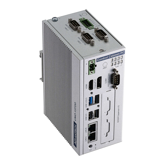
The well-designed heat dispassion mechanism enables the UNO- 1372G-J operating in wide temperatures (from -20 to 60°C). The latest UNO-1372G-J includes Intel Celeron J1900 platform and builds in 4G DDR3L RAM. It provides rich interfaces including 2 x GbE LAN, 1 x USB3.0, 3 x USB2.0 ports, 4 COM ports and 4DI/4DI. -
Page 13: Accessories
1 x drive bay for SATA 2.5" HDD (Compatible with 9.5mm height HDD) – Expansion: 2 x Full size mPCIe slots (one mPCIe also supports mSATA) – Display: 1 x DP, support 2560 x 1440 @60Hz, 1 x HDMI, support 1920 x 1080 @60Hz – TPM: TPM2.0 UNO-1372G-J User Manual... - Page 14 UNO-1372G-J User Manual...
-
Page 15: Chapter 2 Hardware Functionality
Chapter Hardware Functionality This chapter shows how to setup the UNO-1372G-J’s hardware functions, including connecting peripherals, setting switches and indicators. Sections include: Introduction COM1~4: Serial Port LAN / Ethernet Connector Power Connector USB Connector RTC Battery Specification ... -
Page 16: Introduction
Introduction The following figures show the connectors on UNO-1372G-J. The following sections give you information about each peripheral. Figure 2.1 Front Panel of UNO-1372G-J UNO-1372G-J User Manual... -
Page 17: Com1~4: Serial Ports
(Refer to Appendix A.7). LAN: Ethernet Connector UNO-1372G-J is equipped with a two Gigabit LAN controller. The controller chip used is an Intel i210 Ethernet controller that is fully compliant with IEEE 802.3u 10/100/ 1000 Base-T. The Ethernet port is a standard RJ-45 jack, and LED indicators are on the front to show its Link (off/ Green/ Orange LED) and Active (Green LED) status (Refer to Appendix A.10). -
Page 18: Usb Connector
The default setting of UNO-1372G-J is AT mode. UNO-1372G-J will be automatically turned on while there is power input. The "PWR" button can power off the system. UNO-1372G-J is also able to be switched to ATX mode for powering on and off via BIOS (Refer to Appendix A.8). -
Page 19: Led Indicators
Input Voltage (Wet Contact), Configure SW6 to 1,3 – Logic 0: 0~3 VDC – Logic 1: 10~30 VDC Input Voltage (Dry Contact), Configure SW6 to 2,4 – Logic 0: Open – Logic 1: Shorted to GND Input Current UNO-1372G-J User Manual... -
Page 20: Digital Output
Overvoltage Protection: 30 V ESD Protection: 4KV (Contact), 8KV (Air) Opto-Isolator Response: 50 μs 2.11.2 Digital Output Channels: 4 Output Voltage: 5~30VDC Output Capability Sink: 24 mA max./channel Opto-Isolator Response: 50 μs UNO-1372G-J User Manual... -
Page 21: Chapter 3 Initial Setup
Chapter Initial Setup This chapter introduces how to initialize the UNO-1372G-J. Sections include: Chassis Grounding Connecting Power Open & Close Side Cover Installing a Hard Disk Din Rail Mount... -
Page 22: Chassis Grounding
Chassis Grounding UNO-1372G-J provides good EMI protection and a stable grounding base. There is an easy-to-connect chassis grounding point to use. Connecting Power This product is intended to be supplied by an approved power adapter or DC power source, rated at 10 - 36Vdc, 6.0-1.5A and Tmax 60 degree C, if you need further assistance, please contact Advantech for further information. - Page 23 Close side cover: Align the guide pillar between left cover & bracket. Slide in side cover to fix position. Lock the side cover with two screws. UNO-1372G-J User Manual...
-
Page 24: Installing A Hard Disk
Installing a Hard Disk Follow below steps to install a hard disk into the UNO-1372G-J. Remove the power cord. Unscrew and open the side cover Screw HDD to the left cover. Connect SATA cable with HDD then close the side cover. -
Page 25: Din Rail Mount
Din Rail Mount The UNO-1372G-J supports Din-Rail mounting. The assembly instructions are below. Screw DIN rail kit on the back of UNO-1372G-J with 3 screws. Install UNO-1372G-J on the rail. UNO-1372G-J User Manual... - Page 26 UNO-1372G-J User Manual...
-
Page 27: Appendix A System Settings/Pin Assignments
Appendix System Settings/Pin Assignments... -
Page 28: Cn10 Internal Gpio Pin Header
GPO3 GPI3 Board Connectors and Jumpers There are several connectors and jumpers on the UNO-1372G-J board. The follow- ing sections tell you how to configure the UNO-1372G-J hardware setting. Figure A.1 shows the locations of UNO-1372G-J’s connectors and jumpers. Figure A.1 Connector & Switch Locations on MB(Top) -
Page 29: Figure A.2 Connector & Switch Locations On Io Board
PCI Express mini card socket Table A.3: Connectors and Jumpers IO board Digital Input/Output Connector COM3/4 Pin header RS-485 Auto flow control Dry/Wet Contact Setting of Digital Input SW2~5 COM port RS-232/422/485 mode setting COM1~2 COM1/2 port connector CN7 UNO-1372G-J User Manual... -
Page 30: Power Connector (Pwr)
Signal Name ML_Lane 0 (p) ML_Lane 0 (n) ML_Lane 1 (p) ML_Lane 1 (n) ML_Lane 2 (p) ML_Lane2 (2) ML_Lane 3 (p) ML_Lane 3 (n) CONFIG1 CONFIG2 AUX CH (p) AUX CH (n) Hot Plug Return DP_PWR UNO-1372G-J User Manual... -
Page 31: Usb3.0
TMDS Data2 Shield TMDS Data2- TMDS Data1+ TMDS Data1 Shield TMDS Data1- TMDS Data0+ TMDS Data0 Shield TMDS Data0- TMDS Clock+ TMDS Clock Shield TMDS Clock- Reserved DDC/CEC/HEC Ground +5 V Power (max 50 mA) Hot Plug Detect UNO-1372G-J User Manual... -
Page 32: Com1/Com2/Com3/Com4 Rs232/422/485 Connector
COM1/COM2/COM3/COM4 RS232/422/485 connector RS232 RS422 RS485 A.7.1 COM port setting RS232 RS422 RS485 COM1 COM2 COM3 COM4 UNO-1372G-J User Manual... -
Page 33: Power Mode Setting
USB 2.0 specification USB_D- PETp0 PCI Express differential transmit pair SMB_DATA PETn0 SMBus data signal compliant to the SMBus 2.0 specification SMB_CLK +1.5V PERp0 PCI Express differential receive pair +3.3Vaux PERn0 PERST# Functional reset to the card UNO-1372G-J User Manual... - Page 34 * +3.3Vaux was suspend Power , power out to device +3.3V/1.1A * +3.3V was core power * +1.5V was core power, power out to device +1.5V/0.5A UNO-1372G-J User Manual...
-
Page 35: Lan Rj45 Connector
1000BASE-T: In MDI and in MDI-X configuration, MDI[2]+/- corresponds to BI_DC+/- and MDI[3]+/- corre- MDI2- sponds to BI_DD+/-. 100BASE-TX: Unused. MDI3+ 10BASE-T: Unused. MDI3- Left LED Right LED 10Link 100Link 1000 Link Active Orange Green Green UNO-1372G-J User Manual... - Page 36 No part of this publication may be reproduced in any form or by any means, electronic, photocopying, recording or otherwise, without prior written permis- sion of the publisher. All brand and product names are trademarks or registered trademarks of their respective companies. © Advantech Co., Ltd. 2017...
Need help?
Do you have a question about the UNO-1372G-J and is the answer not in the manual?
Questions and answers