Dahua Villa VTO Quick Start Manual
Version 3.1
Hide thumbs
Also See for Villa VTO:
- User manual (32 pages) ,
- User manual (32 pages) ,
- User manual (35 pages)
Table of Contents
Advertisement
Advertisement
Table of Contents

Related Manuals for Dahua Villa VTO


Summary of Contents for Dahua Villa VTO
- Page 1 Villa VTO (Version 3.1) Quick Start Guide V1.0.1...
-
Page 2: Cybersecurity Recommendations
Cybersecurity Recommendations Mandatory actions to be taken towards cybersecurity 1. Change Passwords and Use Strong Passwords: The number one reason systems get “hacked” is due to having weak or default passwords. It is recommended to change default passwords immediately and choose a strong password whenever possible. - Page 3 ● Only forward the HTTP and TCP ports that you need to use. Do not forward a huge range of numbers to the device. Do not DMZ the device's IP address. ● You do not need to forward any ports for individual cameras if they are all connected to a recorder on site;...
- Page 4 Ideally, you want to prevent any unauthorized physical access to your system. The best way to achieve this is to install the recorder in a lockbox, locking server rack, or in a room that is behind a lock and key. 15.
-
Page 5: Foreword
Foreword General This document mainly introduces structure, mounting process, debugging and verification process of villa VTO products. Device Upgrade Please don’t cut off power supply during device upgrade. Power supply can be cut off only after the device has completed upgrade and has rebooted. - Page 6 About the Manual The Manual is for reference only. If there is inconsistency between the Manual and the actual product, the actual product shall prevail. We are not liable for any loss caused by the operations that do not comply with the Manual. ...
-
Page 7: Important Safeguards And Warnings
Important Safeguards and Warnings The following description is the correct application method of the device. Please read the manual carefully before use, in order to prevent danger and property loss. Strictly conform to the manual during application and keep it properly after reading. Operating Requirement Please don’t place and install the device in an area exposed to direct sunlight or near heat ... -
Page 8: Table Of Contents
Table of Contents Cybersecurity Recommendations ......................II Foreword ..............................V Important Safeguards and Warnings ....................VII 1 Product Structure ..........................1 1.1 VTO6210B/BW ..........................1 1.1.1 Front Panel ......................... 1 1.1.2 Rear Panel .......................... 2 1.2 VTO6000CM/VTO6100C ......................4 1.2.1 Front Panel ......................... 4 1.2.2 Rear Panel .......................... -
Page 9: Product Structure
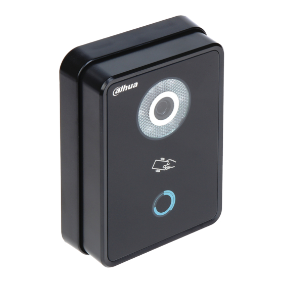
Product Structure VTO6210B/BW 1.1.1 Front Panel Figure 1-1 Name Description Fill-in light Provide fill-in light for camera in case of insufficient light. Camera Monitor the door area. Open the door with authorized IC card and swiping card. Card swiping area Ensure that access extension module has been connected. -
Page 10: Rear Panel
1.1.2 Rear Panel Figure 1-2 Name Description When VTO is detached from the wall forcibly, give out alarm sound Tamper switch and report alarm info to management center. Network port Insert network cable (RJ45 plug). Power port Connect 12V DC power supply. RS485 port Be able to connect access extension module. - Page 11 Name Description Tamper When VTO is detached from the wall forcibly, give out alarm sound and switch report alarm info to management center. Network port Insert network cable (RJ45 plug). Power port Connect 12V DC power supply. Provide lock port, door sensor feedback port and exit button port to connect electric control lock, solenoid lock and exit button.
-
Page 12: Vto6000Cm/Vto6100C
VTO6000CM/VTO6100C 1.2.1 Front Panel Figure 1-6 Figure 1-7 Name Description Fill-in light Provide fill-in light for camera in case of insufficient light. Camera Monitor the door area. Open the door with authorized IC card (card issuing function) and swiping card. Card swiping area Only VTO6100C supports to exit with IC card. -
Page 13: Rear Panel
1.2.2 Rear Panel Figure 1-8 Name Description Network port Insert network cable (RJ45 plug). Power port Connect 12V DC power supply. Debugging port It is used by engineering personnel during debugging. Green plug port 1 Provide lock port, door sensor feedback port and exit button port to connect electric control lock, solenoid lock and exit button. -
Page 14: Vto2000A/Vto2000A-2
Figure 1-9 Figure 1-10 VTO2000A/VTO2000A-2 1.3.1 Front Panel Figure 1-11 Name Description Microphone Audio input. Camera Monitor the door area. Fill-in light Provide fill-in light for camera in case of insufficient light. -
Page 15: Rear Panel
Name Description Speaker Audio output. User directory Set user info. Call key Call management center or VTH. Table 1-6 1.3.2 Rear Panel Figure 1-12 Name Description Camera angle adjusting Adjust camera angle. column When VTO is detached from the wall forcibly, give out alarm sound Tamper switch and report alarm info to management center. - Page 16 Figure 1-13 Figure 1-14...
- Page 17 Figure 1-15 Name Description Camera angle Adjust camera angle. adjusting column When VTO is detached from the wall forcibly, give out alarm Tamper switch sound and report alarm info to management center. Provide power port, 2-wire port, lock port, door sensor feedback port and exit button port to connect power supply, User port 2-wire VTH, electric control lock, solenoid lock and exit button.
- Page 18 Figure 1-17...
-
Page 19: Mounting And Debugging
Mounting and Debugging Mounting Don’t install VTO in bad environment, such as condensation, high temperature, stained, dusty, chemically corrosive, direct sunshine or completely unsheltered environment. Engineering mounting and debugging shall be done by professional teams. Please don’t dismantle or repair arbitrarily in case of device failure. 2.1.1 VTO6210B and VTO6210BW Before installing the bracket or flush mount box, cables in the wall shall be led through the bracket or flush mount box. -
Page 20: Vto6000Cm And Vto6100C
Figure 2-1 2.1.2 VTO6000CM and VTO6100C Before installing the bracket or flush mount box, cables in the wall shall be led through the bracket or flush mount box. Try not to install VTO6100C onto an iron door directly. Otherwise, signals may be shielded and card induction may be poor. -
Page 21: Vto2000A/Vto2000A-2
Figure 2-2 2.1.3 VTO2000A/VTO2000A-2 VTO2000A and VTO2000A-2 devices support the same mounting method and process. Take “VTO2000A” for example. 2.1.3.1 Surface Mounting Step 1 Drill holes according to hole positions of sheet metal bracket, and put expansion pipe in place. Step 2 Connect cables. - Page 22 Figure 2-3 Step 4 Fix the bare device onto sheet metal bracket with M3×6 screws. Figure 2-4...
-
Page 23: Flush Mounting
2.1.3.2 Flush Mounting Step 1 Dig a hole in the wall, embed flush mounting box into the wall, and ensure that box edge clings to the wall. Hole dimension is 117mm×128mm×80mm. During flush mounting, lead cables out from the wall. ... -
Page 24: Debugging
Figure 2-6 Debugging Carry out debugging to ensure that the device can realize basic network access, call and monitoring functions after installation. Before debugging, please check whether the following work has been completed. Debugging personnel shall get familiar with relevant documents in advance, and get to know device mounting, wiring and use. - Page 25 Figure 2-7 According to interface prompt, enter “New Password” and “Confirm”, and click “Next”. Step 2 Select “Email” and enter your Email address. This Email address is used to reset the password, so it is recommended that it should be set. Step 3 Login WEB interface.
- Page 26 the planned network segment and login WEB interface again. Login WEB interface again; select “System Config > LAN Config”. Step 6 The system displays “LAN Config” interface, as shown in Figure 2-9. Figure 2-9 Enter VTO “Building No.”, “Building Unit No.” and “VTO No.”. To call the management center, please tick “Register to the MGT Center”, and ...
-
Page 27: Vth Settings (Version 3.1)
Click “OK”. 2.2.2 VTH Settings (Version 3.1) For the first time, please initialize the password and bind Email. Password is used to enter project setting interface, while Email is used to retrieve your password when you forget it. Step 1 Power on the device. - Page 28 Figure 2-12 Set according to actual network access mode. Static IP Select “Static IP”. Enter “Local IP”, “Subnet Mask” and “Gateway”. DHCP Select “DHCP” to obtain IP address automatically. Click [OK] to save the settings. Step 7 Press [Product Info]. The system displays “Product Info”...
- Page 29 WEB interface. Otherwise, it will fail to connect VTO. Be used as an extension VTH. Press [Master] and switch to “Extension”. Enter “Room No.” (such as 9901-1) and “Master IP” (IP address of master VTH). “User Name” and “Password” are the user name and password of master VTH. Default user name is admin, and the password is the one set during device initialization.
-
Page 30: Vth Settings (Version 4.0)
Switch “Enable Status” to Add fence station. Press to switch to sub VTO setting interface. Select device type to be “fence station”; enter sub VTO name (fence station name), VTO middle no. (fence station middle no.), “User Name” and “Password”. Fence station middle no. - Page 31 The system displays “Network” interface, as shown in Figure 2-16 or Figure 2-17. Please set according to network access mode in actual application. IP addresses of VTH and VTO shall be in the same network segment. Otherwise, VTH will fail to obtain VTO info after configuration. Figure 2-16 Figure 2-17 Wired IP...
- Page 32 The system displays available WIFI list, as shown in Figure 2-18. Figure 2-18 Connect WIFI. The system has 2 access ways as follows. At “WLAN” interface, select WIFI, click “Wireless IP” tab to enter “Local IP”, ◇ “Subnet Mask” and “Gateway”, and press [OK]. At “WLAN”...
- Page 33 Figure 2-20 Be used as a master VTH. Enter “Room No.” (such as 9901) and click “OK”. “Room no.” shall be the same with “VTH Short No.”, which is set when adding VTH at WEB interface. Otherwise, it will fail to connect VTO. Be used as an extension VTH.
- Page 34 Figure 2-21 Add main VTO. In Figure 2-21, enter main VTO name, VTO IP, “User Name” and “Password”. Switch the “Enable Status” to be Default device type is “Door”. VTO middle no. will be obtained automatically. The format is “1+building no.+ unit no. + VTO no.”. Building no. has 2 digits, unit no.
-
Page 35: Debugging Verification
example, 10006901. Switch the “Enable Status” to be Debugging Verification 2.3.1 Verification with Version 3.1 VTH 2.3.1.1 VTO Calls VTH Press call key at VTO, to call VTH. VTH pops up monitoring image and operating keys, as shown in Figure 2-22. It represents successful debugging. Figure 2-22 2.3.1.2 VTH Monitors VTO VTH is able to monitor VTO, fence station or IPC. -
Page 36: Verification With Version 4.0 Vth
Figure 2-23 Figure 2-24 2.3.2 Verification with Version 4.0 VTH 2.3.2.1 VTO Calls VTH Press call key at VTO, to call VTH. VTH pops up monitoring image and operating keys, as shown in Figure 2-25. It represents successful debugging. The following figure means that SD card has been inserted into VTH. If SD card is not inserted, recording and snapshot icons are gray. - Page 37 Figure 2-25 2.3.2.2 VTH Monitors VTO VTH is able to monitor VTO, fence station or IPC. Take “VTO” for example. Select “Monitor > Door”, as shown in Figure 2-26. Select the VTO to enter monitoring image, as shown in Figure 2-27. The following figure means that SD card has been inserted into VTH.
- Page 38 Figure 2-27...
Need help?
Do you have a question about the Villa VTO and is the answer not in the manual?
Questions and answers
How can I Villa VTO ring button connect over VTH to handy tel. number to get one call from Villa VTO at the door.Please for instruction. Thank you.