Dahua VTO2000A Series User Manual
Hide thumbs
Also See for VTO2000A Series:
- Quick start manual (28 pages) ,
- Connection manual (16 pages) ,
- Quick install manual (13 pages)
Table of Contents
Advertisement
Advertisement
Table of Contents

Related Manuals for Dahua VTO2000A Series


Summary of Contents for Dahua VTO2000A Series
- Page 1 VTO2000A Series User’s Manual V1.1.0...
-
Page 2: Table Of Contents
Table of Contents Table of Contents ...................... 2 Product Overview ..................1 List of Models ....................1 Structure ......................1 1.2.1 Structure ....................1 1.2.2 Front Panel ................... 2 1.2.3 Rear Panel .................... 3 Networking Scene ................... 3 1.3.1 One-to-One Scene ................3 1.3.2 Group Call Scene .................. - Page 3 System Config ....................1 4.1.1 Local Config ..................1 4.1.2 LAN Config ................... 4 4.1.3 Indoor Manager ..................4 4.1.4 Network Config ..................5 4.1.5 Video Set ....................7 4.1.6 User Manage ..................8 IPC ........................ 10 Info Search....................10 4.3.1 Call History ..................
- Page 4 Important Safeguards and Warnings Please read the following safeguards and warnings carefully before using the product in order to avoid damages and losses. Note: Do not expose the device to lampblack, steam or dust. Otherwise it may cause fire or electric shock. ...
-
Page 5: Product Overview
1 Product Overview 1.1 List of Models Model Chassis Color Unlock Button Type Lock Control Module Material IC card VTO2000A Metal Silver Mechanical Built-in 1.2 Structure 1.2.1 Structure Before installation, please make you sure know the dimensions of device and select appropriate method of installation. -
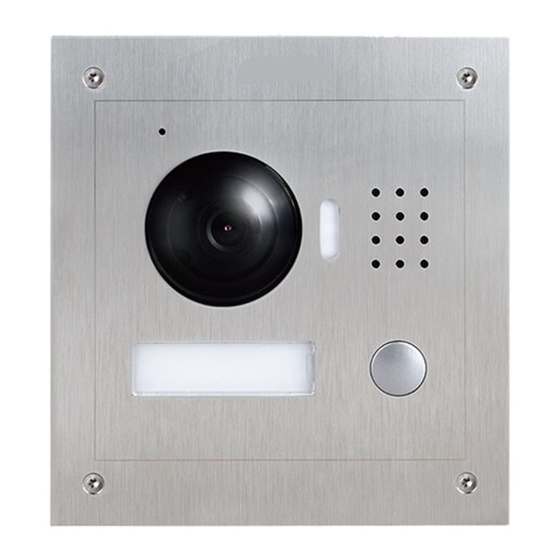
Page 6: Front Panel
1.2.2 Front Panel Figure 1- 2 Port Name Note Audio input. Camera It monitors corresponding door region. Light compensation will automatically turn on Compensation during monitoring, calling, or connecting status if Light there is no enough light in environment. Speaker Audio output. -
Page 7: Rear Panel
1.2.3 Rear Panel Figure 1- 3 Component Name Note Camera Angle Adjust camera angle. Adjustment Vandal-proof When VTO if forced to leave wall, it will alarm and Switch report to MGT center. Via convertor, connect network cable (RJ45 Network Port crystal head). -
Page 8: Group Call Scene
Figure 1- 4 1.3.2 Group Call Scene When visitor press Call on VTO, multiple VTH will ring at the same time. The resident can anwer, hang up or unlock door from any of the VTHs. Note: VTH has main VTH (host) and sub VTH (extension). One host can have up to 3 extensions. -
Page 9: Install Vto
2 Install VTO VTO installation includes direct and embedded wall installation. Direct installation is to install VTO in wall while embedded-wall is to dig a hole on wall and embed VTO into the hole. This chapter separately introduces these two methods. Direct Installation 2.1.1 Screw Before installing VTO, please check screws on accessory bag according to the following... -
Page 10: Installation Step
Figure 2- 1 2.1.3 Installation Step Step 1. Install metal bracket into the groove on wall. Fasten screw (ST3×18 Cross recessed countersunk head tail tapping screws --- galvanizing white), and fix metal bracket on wall. See Figure 2- 2 Step 2. Align the device on metal bracket according to screw hole. Fasten screw (M3×8 Cross recessed countersunk head tail machine screws --- galvanizing white), and fix device on metal bracket. - Page 11 Figure 2- 2...
-
Page 12: Embedded In Wall
Figure 2- 3 2.2 Embedded in Wall 2.2.1 Screw Before installing VTH, please check screws on accessory bag according to the following specifications and install by following this guide. Component Illustration Quantity M3×6 Hex slot pan head tail machine screws--- galvanizing white M3×8 Cross recessed countersunk head tail machine screws --- galvanizing white Chart 2- 2... -
Page 13: Dimension
2.2.2 Dimension Before you install the device, please make sure you know the dimension of device and select appropriate installation method. See Figure 2- 4. Figure 2- 4 2.2.3 Installation Step Step 1. Dig a hole on wall, its dimension is 117*128*80(mm).See Figure 2- 5. Step 2. - Page 14 Figure 2- 5 Figure 2- 6...
-
Page 15: Wiring
Figure 2- 7 2.3 Wiring See Figure 2- 8. Figure 2- 8 Component Note Name Via convertor, connect to network cable. (RJ45 Network Port crystal head). -
Page 16: Electric Control Lock And Electromagnetic Lock
Power supply, connect to lock, door sensor and User Port unlock button. Project Port Reserved for project staff use. 2.4 Electric Control Lock and Electromagnetic Lock 2.4.1 Electric Control Lock When VTO connects to electric control lock, it means that the positive end of electronic control lock connects to NO of VTO (user port 10) while its negative end connects to COM of VTO (user port 12). - Page 17 Figure 2- 10...
-
Page 18: Installation Debugging
3 Installation Debugging Warning: Before debugging, the staff shall be familiar with device’s installation, wiring and usage. Beore debugging, check wiring for short or open circuit. When staff find each circuit is normal, plug the device to power. ... -
Page 19: General Config
Select System Config>Network, set VTO IP address, subnet mask and defaul gateway. Click OK, see Figure 3- 2. Figure 3- 2 3.2 General Config If you first use VTO, you may need to operate according to the following steps: Step 1. In Internet Explorer, input IP address of the VTO, enter username and password, click Login to login WEB. - Page 20 Step 3. In System Time tab, click on Sync PC to make VTO time the same with PC. Step 4. Select System Config>Network Config, set VTO IP, Subnet Mask and Default Gateway. See 错误!未找到引用源。.
-
Page 21: Web Config
4 Web Config This chapter introduces VTO WEB interface and its parameters, and how to configure them. 4.1 System Config 4.1.1 Local Config 4.1.1.1 Local Config In Local Config interface, you can view VTO model, version info and etc. Figure 4- 1 Parameter Note Sensor... - Page 22 Figure 4- 2 Parameter Note Unlock Responding The interval between current unlock and next one, Interval unit is second. Unlock Period Period door remains unlocked, unit is second. When only use door sensor, check”Check Door Door Sensor Check Sensor Signal Before Lock”, Set “Door Sensor Check Time Time”...
- Page 23 Figure 4- 4 4.1.1.5 Config Manager You can import and export configuration, or restore default setup. Figure 4- 5 Parameter Note Backup Check “card no.”, “VTH info”, and click ,so you can back up card no. and VTH info. Restore Backup Check “card no.”, “VTH info”, and click to recover card no.
-
Page 24: Lan Config
4.1.2 LAN Config Here you can register VTO to center and set how to call center. Please refer to Ch 5.1.1. 4.1.3 Indoor Manager In Indoor Manager interface, you can add, delete and modify VTH (digital indoor station),. For example to add digital VTH: Step 1. -
Page 25: Network Config
Figure 4- 7 Click , in pop-up modification page modify VTH info. When you modify digital VTH, you can only modify name and nickname. When you modify analog VTH, you can only modify name, nickname, distributor address and distributor port. ... - Page 26 After you have modified IP address, WEB page will reboot and go to the new IP address page. 4.1.4.2 FTP FTP server is used to store record, snapshot picture and etc. User can login FTP server to view and get photo or image. You can go to System Config>Network>FTP, to set local FTP network parameter.
-
Page 27: Video Set
4.1.5 Video Set You can go to System Config>Video Set interface to set video and audio. Step 1. Select System Config>Video Set. Step 2. Adjust video parameter. See Figure 4- 11. Figure 4- 11 Parameter Note Video Format By resolution, there are WVGA and D1. WVGA:800*480 pixels D1:704*576 pixels. -
Page 28: User Manage
Unlock Unlock via web. Step 3. Click audio setup tab, adjust audio parameter. Figure 4- 12 4.1.6 User Manage Only when you login as admin, you can add, modify, delete and view user info in User Manage interface. Current system supports two types of user: ... - Page 29 Step 4. Click 4.1.6.2 Modify User Admin and user support to modify user password, but cannot modify note information or delete it. Step 1. Select System Config>User Manager, enter User Manager interface. See Figure 4- 14. Figure 4- 14 Step 2. Click to delet user.
-
Page 30: Ipc
4.2 IPC If the VTH has configured with IPC info, you can view IPC video image via corresponding VTH. You can go to System Config>IPC info interface, view and modify all IPC info. Step 1. Select System Config>IPC info. Step 2. Click Step 3. -
Page 31: Alarm Record
Figure 4- 17 4.3.2 Alarm Record You can search VTO alarm in Alarm Record interface, and it stores up to 1024 records. Figure 4- 18 4.3.3 Unlock Record You can search VTO unlock records in Unlock Record interface, and it stores up to 1024 records. -
Page 32: Status Statistics
4.4 Status Statistics 4.4.1 VTH Status In VTH status, you can view VTH connection status. Status Offline: Connection between VTO and VTH is disconnected; you cannot call, monitor or talk. Online: Connection between VTO and VTH is ready, you can call, monitor and talk. ... -
Page 33: Basic Function Introduction
5 Basic Function Introduction 5.1 Call Function 5.1.1 Call Resident Press Call button under standby status, and the VTO will call user. User may monitor VTO from VTH. On VTH, press Unlock button to unlock door. When VTH picks up, you can start talk with the VTH. ... - Page 34 Figure 5- 1 Note: Parameter with * is madantory, while others are optional. Step 4. In LAN Config interface, check group call, click OK. Step 5. After config is complete, enter logout interface, reboot VTO. See Figure 5- 2. Figure 5- 2 Configure Main VTH Step 1.
- Page 35 Figure 5- 3 Step 3. Press network, fill in VTO IP address. Figure 5- 4 Set Extension Step 1. In VTH screen, press System Config, and press project settings, input password (default is 002236), and enter project settings interface. Step 2. Press local info. Press master and it changes to extension. Step 3.
-
Page 36: Monitor
with user config on the main VTH. Figure 5- 5 5.2 Monitor Both VTS and VTH are able to monitor this VTO and remotely view camera captured image on VTH. 5.3 Unlock Function Unlock by Center When center is called, calling or monitoring, center can remotely unlock door. VTO will return to standby interface after call ends or countdown stops. -
Page 37: Vandal Proof
achieves light compensation in connecting status. 5.5 Vandal Proof There is one channel of vandal proof which will generate alarm sound and report to the manager center once VTO is forced to leave the wall. 5.6 Restore Backup Restore Card Info If you encounter abnormality with card info or accidently restore default settings, you can restore card info with this function. -
Page 38: Faq
6 FAQ Q: I pressed Call button, and the indicator turned on, but the VTO did not start a call? A: Please check your operation process. Q: How to end a call when I am calling? A: Please press button on VTO and there will be sound from the device. Q: The device could not boot up and there was no sound or light. -
Page 39: Appendix 1 Technical Specifications
Appendix 1 Technical Specifications Model VTO2000A Main Process Embedded micro controller System Embedded Linux os Video Compression H.264 Standard Video Input/Sensor Megapixel CMOS HD camera Night Vision Support Input Omnidirectional Mic Audio Output Built-in speaker Talk Support bidirectional talk Input Single key input Operation Door Lock... -
Page 40: Appendix 2 Accessories
Appendix 2 Accessories Appendix 2.1 Cable Specification The wiring length between VTO and VTH is L , so reasonable specification of wiring is: ≤50m ≤100m Cable Specification 0<L 50<L UTP Cat5e/Cat6: 10 ohm/100m Optional Optional UTP Cat5e/Cat6: 18.8 ohm/100m Optional Not optional Note: Please do not let L... - Page 41 Note: This manual is for reference only. Slight difference may be found in user interface. All the designs and software here are subject to change without prior written notice. All trademarks and registered trademarks are the properties of their respective owners.
Need help?
Do you have a question about the VTO2000A Series and is the answer not in the manual?
Questions and answers