Table of Contents
Advertisement
Quick Links
Advertisement
Table of Contents

Subscribe to Our Youtube Channel
Related Manuals for Dahua VTO Series


Summary of Contents for Dahua VTO Series
- Page 1 Unit VTO (Version 4.3) Quick Start Guide V1.0.1...
-
Page 2: Cybersecurity Recommendations
Cybersecurity Recommendations Mandatory actions to be taken towards cybersecurity 1. Change Passwords and Use Strong Passwords: The number one reason systems get “hacked” is due to having weak or default passwords. It is recommended to change default passwords immediately and choose a strong password whenever possible. - Page 3 ● Only forward the HTTP and TCP ports that you need to use. Do not forward a huge range of numbers to the device. Do not DMZ the device's IP address. ● You do not need to forward any ports for individual cameras if they are all connected to a recorder on site;...
- Page 4 Ideally, you want to prevent any unauthorized physical access to your system. The best way to achieve this is to install the recorder in a lockbox, locking server rack, or in a room that is behind a lock and key. 15.
-
Page 5: Regulatory Information
Regulatory Information The regulatory information herein might vary according to the model you purchased. Some information is only applicable for the country or region where the product is sold. FCC Information Changes or modifications not expressly approved by the party responsible for compliance could void the user's authority to operate the equipment. -
Page 6: Foreword
Foreword General This Guide introduces the structure, mounting process, and basic configuration of the device. Safety Instructions The following categorized signal words with defined meaning might appear in the Guide. Signal Words Meaning Indicates a medium or low potential hazard which, if not avoided, could result in slight or moderate injury. - Page 7 All the designs and software are subject to change without prior written notice. The product updates might cause some differences between the actual product and the Guide. Please contact the customer service for the latest program and supplementary documentation. There still might be deviation in technical data, functions and operations description, or ...
-
Page 8: Important Safeguards And Warnings
Important Safeguards and Warnings The following description is the correct application method of the device. Please read the manual carefully before use, in order to prevent danger and property loss. Strictly conform to the manual during application and keep it properly after reading. Operating Requirement Please don’t place and install the device in an area exposed to direct sunlight or near heat ... -
Page 9: Table Of Contents
Table of Contents Cybersecurity Recommendations ......................II Regulatory Information ..........................V Foreword ..............................VI Important Safeguards and Warnings ....................VIII 1 Overview .............................. 1 Introduction ........................... 1 Features ............................1 2 Appearance ............................3 VTO1220A/VTO1210A-X ......................3 2.1.1 Front Panel ......................... 3 2.1.2 Rear Panel .......................... - Page 10 5.4.1 Calling VTH from VTO ...................... 25 5.4.2 Doing Monitor from VTH ....................25 6 Operating VTO ............................. 27 Call Function ..........................27 6.1.1 Calling with Room Number ....................27 6.1.2 Calling with Contact ......................27 Unlock Function .......................... 27 6.2.1 Unlock with IC Card ......................
-
Page 11: Overview
Overview Introduction This unit video intercom outdoor station (hereinafter referred to as “the VTO”) can be connected to the video intercom home station (VTH), video intercom master station (VTS), or third party servers to constitute a video intercom system, which supports video call between visitors and residents. - Page 12 History Viewing View call history, alarm history, and unlocking history. Motion Detection The VTO screen lights up when moving objects are approaching. 错误!使用“开始”选项卡将 Heading 1 应用于要在此处显示的文字。 2...
-
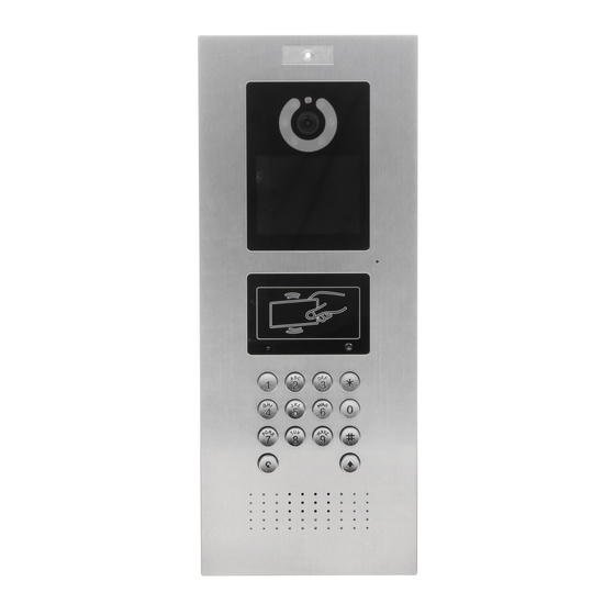
Page 13: Appearance
Appearance VTO1220A/VTO1210A-X 2.1.1 Front Panel VTO1220A/VTO1210A-X Table 2-1 Front panel description Name Description Light sensor Senses ambient light to turn on or off the fill light. Fill light Provides extra light for the camera. Inputs audio. 错误!使用“开始”选项卡将 Heading 1 应用于要在此处显示的文字。 3... -
Page 14: Rear Panel
Name Description : Press to delete the previous character or end the current call. Numeric keys: enter numbers from 0 to 9. : Press to unlock with password. Dialing area Press , then enter the unlock password, and then press again to complete. -
Page 15: Vto1220Bw/Vto1210B-X
Name Description RS-485/RS-482 port See "2.4.2 RS-485/RS-482 Port." Ethernet port Connects to the network with Ethernet cable. Access input port See "2.4.1 Access Control Input and Output Port." Analog signal port See "2.4.3 Analog Signal Port." The VTO would make alarm sound if it is being Tamper alarm removed from the wall by force, and the alarm will also be sent to the management center. -
Page 16: Rear Panel
Name Description : Press to deletes the previous character or end the current call. Numeric keys: enter numbers from 0 to 9. : Press to unlock with password. Press , then enter the unlock password, and then press Dialing area again to complete. -
Page 17: Vto1210C-X
Name Description The VTO would make alarm sound if it is being Tamper alarm removed from the wall by force, and the alarm will also be sent to the management center. Access output port See "2.4.1 Access Control Input and Output Port." Ethernet port Connects to the network with Ethernet cable. -
Page 18: Rear Panel
Name Description : Press to deletes the previous character or end the current call. Numeric keys: enter numbers from 0 to 9. : Press to unlock with password. Dialing area Press , then enter the unlock password, and then press again to complete. -
Page 19: Rs-485/Rs-482 Port
Solenoid lock connection Motor lock connection 2.4.2 RS-485/RS-482 Port This port can be used to connect to 485/422 devices. For the detailed connection method, see Figure 2-9, Figure 2-10 and Figure 2-11. 错误!使用“开始”选项卡将 Heading 1 应用于要在此处显示的文字。 9... -
Page 20: Analog Signal Port
RS-485/RS-482 Port (1) RS-485/RS-482 Port (2) RS-485/RS-482 Port (3) 2.4.3 Analog Signal Port Analog signal port is only available on models with –X in the name, and it can be used to connect to analog devices. See Figure 2-12. 错误!使用“开始”选项卡将 Heading 1 应用于要在此处显示的文字。 10... - Page 21 Analog signal port 错误!使用“开始”选项卡将 Heading 1 应用于要在此处显示的文字。 11...
-
Page 22: Network Diagram
Network Diagram See Figure 3-1 for the network diagram. Network diagram 错误!使用“开始”选项卡将 Heading 1 应用于要在此处显示的文字。 12... -
Page 23: Installation
Installation Installation Requirement 4.1.1 Notice Do not install the VTO to places with condensation, high temperature, grease or dust, chemical corrosion, direct sunlight, or zero shelter. The installation and adjustment must be finished by professional crew, and do not ... -
Page 24: Installing Vto
Installing VTO 4.2.1 VTO1220A/VTO1210A-X VTO1220A/VTO1210A-X installation Table 4-1 Item list No. Item No. Item No. Item M3×16 screw ST3×18 screw Metal mounting box Expansion tube Wall Cut an opening with the size of the mounting box on the wall, and then drill screw holes in the opening according to the position of the screw holes on the mounting box. -
Page 25: Vto1220Bw/Vto1210B-X
4.2.2 VTO1220BW/VTO1210B-X VTO1220BW/VTO1210B-X installation Table 4-2 Item list No. Item No. Item No. Item Wall Plastic mounting box Bracket ST3×18 screw M3×16 screw Cut an opening with the size of the mounting box on the wall, and then put the mounting box in. -
Page 26: Vto1210C-X
4.2.3 VTO1210C-X 4.2.3.1 Wall Mounted VTO1210C-X wall mounted Table 4-3 Item list No. Item No. Item Item M4×30 screw ST4.2×25 screw Mounting box Wall — — Drill screw holes on the wall according to the position of the screw holes on the mounting box, and then put the expansion tubes in the screw holes. - Page 27 4.2.3.2 Installing with Plastic Mounting Box VTO1210C-X with mounting box Table 4-4 Item list Item No. Item Wall Plastic mounting box M4×40 screw Cut an opening with the size of the mounting box on the wall, and then put the mounting box in.
-
Page 28: Configuration
Configuration This chapter introduces how to initialize, connect, and make primary configurations to the VTO and VTH devices to realize basic functions, including device management, calling, and monitoring. For more detailed configuration, see the user's Manual. Configuration Process Before configuration, check every device and make sure there is no short circuit or open circuit in the circuits. -
Page 29: Configuring Vto Number
Device initialization Enter and confirm the password, and then click Next. The Email setting interface is displayed. Select the Email check box, and then enter your Email address. This Email address can be used to reset the password, and it is recommended to finish this setting. Click Next. -
Page 30: Configuring Network Parameters
Main interface Select Local Setting > Basic. The device properties are displayed. See Figure 5-4. Device properties In the VTO No. input box, enter the VTO number you planned for this VTO, and then click Confirm to save. 5.3.3 Configuring Network Parameters Select Network Setting >... -
Page 31: Configuring Sip Server
5.3.4 Configuring SIP Server The SIP server is required in the network to transmit intercom protocol, and then all the VTO and VTH devices connected to the same SIP server can make video call between each other. You can use VTO device or other servers as SIP server. Select Network Setting >... -
Page 32: Adding Vto Devices
Select the server type you need in the Server Type list, and then see the corresponding manual for the detailed configuration. 5.3.5 Adding VTO Devices You can add VTO devices to the SIP server, and all the VTO devices connected to the same SIP server can make video call between each other. -
Page 33: Adding Room Number
Configure the parameters, and be sure to add the SIP server itself too. See Table 5-2. Table 5-2 Add VTO configuration Parameter Description The VTO number you configured for the target VTO. See Rec No. the details in "5.3.2 Configuring VTO Number." Register Keep default value. - Page 34 The Add interface is displayed. See Figure 5-10. Add single room number Configure room information. See Table 5-3. Table 5-3 Room information Parameter Description First Name Last Name Enter the information you need to differentiate each room. Nick Name The room number you planned. If you use multiple VTH devices, the room number of the ...
-
Page 35: Verifying Configuration
Add in batch All the added room numbers are displayed. Click Refresh to view the latest status, and click Clear to delete all the room numbers. Verifying Configuration 5.4.1 Calling VTH from VTO Dial room number on the VTO. Press The VTO is calling the VTH. - Page 36 Door Select the VTO you need to do monitor. The monitor screen is displayed. See Figure 5-14. Monitor screen 错误!使用“开始”选项卡将 Heading 1 应用于要在此处显示的文字。 26...
-
Page 37: Operating Vto
Operating VTO Call Function 6.1.1 Calling with Room Number On standby mode, enter room No. on the VTO. Press to call. During phone call, press to end the call. 6.1.2 Calling with Contact All the room numbers added to SIP server is displayed in the VTO contact. On standby mode, press to view contact. -
Page 38: Project Mode
The personal password is the password of your VTH, and it is 123456 by default, you need to change it before using it to unlock the door. See the details in VTH user's manual. Unlock with public password/duress password On standby mode, press #+ public password/duress password +#. -
Page 39: Modifying Ip Address
Swipe the card that needs to be authorized, and then the "Issued card successfully” notice is displayed. 6.3.3 Modifying IP Address In the project mode, select IP Config. Press numeric keys of 2, 8, 4, and 6 to select the item you need to modify, and then press # to start input.
Need help?
Do you have a question about the VTO Series and is the answer not in the manual?
Questions and answers