Table of Contents
Advertisement
Advertisement
Table of Contents

Related Manuals for Dahua VTO2202F


Summary of Contents for Dahua VTO2202F
- Page 1 VTO2202F (Version 1.0) Quick Start Guide V1.0.1...
-
Page 2: Cybersecurity Recommendations
Cybersecurity Recommendations Mandatory actions to be taken towards cybersecurity 1. Change Passwords and Use Strong Passwords: The number one reason systems get “hacked” is due to having weak or default passwords. It is recommended to change default passwords immediately and choose a strong password whenever possible. - Page 3 ● Only forward the HTTP and TCP ports that you need to use. Do not forward a huge range of numbers to the device. Do not DMZ the device's IP address. ● You do not need to forward any ports for individual cameras if they are all connected to a recorder on site;...
-
Page 4: Foreword
Foreword General This Guide introduces the structure, mounting process, and basic configuration of the device. Safety Instructions The following categorized signal words with defined meaning might appear in the Guide. Signal Words Meaning Indicates a medium or low potential hazard which, if not avoided, could result in slight or moderate injury. - Page 5 Please visit our website, contact the supplier or customer service if there is any problem occurred when using the device. If there is any uncertainty or controversy, please refer to our final explanation. Foreword IV...
-
Page 6: Important Safeguards And Warnings
Important Safeguards and Warnings The following description is the correct application method of the device. Please read the manual carefully before use, in order to prevent danger and property loss. Strictly conform to the manual during application and keep it properly after reading. Operating Requirement ... -
Page 7: Table Of Contents
Table of Contents Cybersecurity Recommendations ......................I Foreword ..............................III Important Safeguards and Warnings ..................... V 1 Network Diagram ........................... 1 2 Appearance ............................2 Front Panel ............................ 2 Rear Panel ............................ 3 3 Installation .............................. 4 Installation Requirement ....................... 4 3.1.1 Notice .......................... -
Page 8: Network Diagram
Network Diagram Network Diagram 1... -
Page 9: Appearance
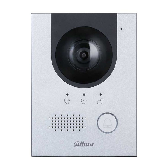
Appearance Front Panel Figure 2-1 Front panel Table 2-1 Front panel description Name Description Inputs audio. Camera Monitors door area. Indicator When you are calling, this indicator will be on. Indicator During the call communication, this indicator will be on. Indicator When the door is unlocked, this indicator will be on. -
Page 10: Rear Panel
Rear Panel Figure 2-2 Rear panel Table 2-2 Rear panel description Name Description Tamper The VTO would make alarm sound if it is being removed from the wall switch by force, and the alarm will also be sent to the management center. GND: Ground. -
Page 11: Installation
Installation Installation Requirement 3.1.1 Notice Do not install the VTO to places with condensation, high temperature, grease or dust, chemical corrosion, direct sunlight, or zero shelter. The installation and adjustment must be finished by professional crew, and do not disassemble the VTO. - Page 12 Liquid sodium silicate is recommended. Figure 3-2 Installed on the wall Table 3-1 Names of numbers (1) Name Waterproof ring ST4×25 self-tapping screw Mounting box M3×8 Screw Waterproof silica gel pad Expansion screw Wall Installation 5...
- Page 13 Figure 3-3 Apply silica gel to gaps Installation 6...
-
Page 14: Installed In The Wall
3.2.2 Installed in the Wall Step 1 Install the mounting box rear cover in the wall. Step 2 Install VTO on the mounting box front cover. Step 3 Fix the VTO to the mounting box front cover by screwing two M3×8 screws into the VTO from the bottom of the mounting box front cover. - Page 15 Figure 3-5 Apply silica gel to gaps Table 3-2 Names of numbers (2) Name M3×8 Screw Waterproof ring Mounting box front box Mounting box rear box Wall Installation 8...
-
Page 16: Configuration
Configuration This chapter introduces how to initialize, connect, and make primary configurations to the VTO and VTH devices to realize basic functions, including device management, calling, and monitoring. For more detailed configuration, see the user's Manual. Configuration Process Before configuration, check every device and make sure there is no short circuit or open circuit in the circuits. -
Page 17: Configuring Vto Number
Figure 4-1 Device initialization Step 3 Enter and confirm the password, and then click Next. The Email setting interface is displayed. Step 4 Select the Email check box, and then enter your Email address. This Email address can be used to reset the password, and it is recommended to finish this setting. Step 5 Click Next. -
Page 18: Configuring Network Parameters
Figure 4-3 Main interface Step 2 Select Local Setting > Basic. The device properties are displayed. See Figure 4-4. Figure 4-4 Device properties Step 3 In the VTO No. input box, enter the VTO number you planned for this VTO, and then click Confirm to save. -
Page 19: Configuring Sip Server
The VTO will reboot, and you need to modify the IP address of your PC to the same network segment as the VTO to log in again. 4.3.4 Configuring SIP Server The SIP server is required in the network to transmit intercom protocol, and then all the VTO and VTH devices connected to the same SIP server can make video call between each other. -
Page 20: Configuring Call No. And Group Call
If other servers work as SIP server Select the server type you need in the Server Type list, and then see the corresponding manual for the detailed configuration. 4.3.5 Configuring Call No. and Group Call You need to configure call No. on every VTO, and then all the VTO will call the defined room when you press the call button. - Page 21 which a VTO device works as SIP server, and if you are using other servers as SIP server, see the corresponding manual for the detailed configuration. Step 1 Log in the web interface of the SIP server, and then select Household Setting > VTO No.
-
Page 22: Adding Room Number
Parameter Description Build No. Available only when other servers work as SIP server. Unit No. IP Address The IP address of the target VTO. Username The user name and password for the web interface of the target VTO. Password Step 4 Click Save. -
Page 23: Verifying Configuration
Figure 4-12 Add single room number Step 3 Configure room information. See Table 4-3. Table 4-3 Room information Parameter Description First Name Last Name Enter the information you need to differentiate each room. Nick Name The room number you planned. ... -
Page 24: Doing Monitor From Vth
Figure 4-13 Call screen on the VTH to answer the call. 4.4.2 Doing Monitor from VTH Step 1 In the main interface of the VTH, select Monitor > Door. The Door interface is displayed. See Figure 4-14. Figure 4-14 Door Step 2 Select the VTO you need to do monitor. - Page 25 Figure 4-15 Monitor screen Configuration 18...
-
Page 26: Connecting Mobile Phone App
Connecting Mobile Phone App You can download the mobile phone app, and then add your villa VTO to the app. When someone is calling you from the villa VTO, there will be push message on your phone, and you can talk to the visitor or unlock the door remotely on your phone. Step 1 Scan the following QR code to download and install the app. - Page 27 Figure 5-3 Step 4 Give a name to your target VTO, and then tap the sign. The mobile phone starts to scan. Step 5 Log in the web interface of the VTO you need to add, and then select Network. The P2P interface is displayed.
- Page 28 Figure 5-5 Live Step 7 Tap Alarm Manager > Subscribe, and then subscribe the VTO you need. See Figure 5-6. Figure 5-6 Subscribe When someone is calling you from the subscribed villa VTO, there will be push message on your phone. See Figure 5-7. Connecting Mobile Phone App 21...
- Page 29 Figure 5-7 Push Connecting Mobile Phone App 22...
Need help?
Do you have a question about the VTO2202F and is the answer not in the manual?
Questions and answers