Table of Contents
Advertisement
Quick Links
MLC Plus 84 EU and MLC Plus 84 MK •
Setup Guide
Y
L A
S P
D I
F
O F
O N
C
D O
M
C A
P C
O P
P T
L A
2
O P
P T
L A
1
A
V G
M I
H D
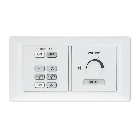
MLC Plus 84 MK Front Panel
Figure 1.
The MLC Plus 84 EU fits most standard two-gang European wall boxes. The MLC Plus 84 MK fits most standard two-gang
MK-type wall boxes. These two models are identical except for the EU- or MK-specific wallplates and mounting hardware.
This guide provides instructions for an experienced installer to install an MLC Plus 84 Series controller and to create a basic
configuration. Configure the controller using Extron Global Configurator (GC) software running in Global Configurator Professional
(GC Professional) or Global Configurator Plus (GC Plus) mode. The MLC integrates with Extron GlobalViewer
software and the GlobalViewer Web-based AV resource management for remote control applications. Global Configurator and
other useful software applications are available at www.extron.com.
Installation
Step 1: Get Ready
…
Download and install the latest version of the following:
Global Configurator software — for setting up and configuring the controller. GC includes the Toolbelt feature and a
•
way to upgrade the firmware of the controller. You must have an Extron Insider account and contact an Extron support
representative to obtain GC software (see
page 11).
IP Link Pro device drivers — for use with GC, to make control of other devices possible.
•
All are avail able from
…
Obtain network information for the unit from the network administrator. You will need the following details for each IP Link Pro device:
…
DHCP setting (on or off)
…
Device (MLC Plus 84) IP address
…
Write down the MAC address of each IP Link Pro device (such as the MLC Plus 84) to be used.
…
Obtain model names and setup information for devices the MLC Plus 84 will control.
Step 2: Prepare the Installation Site
ATTENTION:
Installation and service must be performed by authorized personnel only.
•
L'installation et l'entretien doivent être effectués par le personnel autorisé uniquement.
•
Extron recommends installing the MLC Plus 84 into a grounded electrical junction box.
•
Extron recommande d'installer le MLC Plus 84 dans un boîtier d'encastrement électrique mis à la terre.
•
If the controller will be installed into fine fu niture, it is best to hire a licenced, bonded craftsperson to cut the access
•
hole and perform the physical installation so the surface will not be damaged.
S'il est prévu d'installer le contrôleur dans du beau mobilier, il est préférable de faire appel à un artisan autorisé et
•
qualifié pour couper le t ou d'accès et réaliser l'installation de telle façon que la surface ne soit pas endommagée.
M E
M E
L U
L U
V O
V O
Figure 2.
Locating Software, Firmware, and Driver Files on the Extron Website
www.extron.com
(see
Locating Software, Firmware, and Driver Files on the Extron Website
M E
M E
L U
L U
V O
V O
Y
L A
S P
D I
F
O F
O N
C
D O
M
C A
P C
P
T O
L A P
2
P
T O
L A P
2
1
M I
H D
1
M I
H D
MLC Plus 84 EU Front Panel
…
Subnet mask
…
Gateway IP address
The Extron MLC Plus 84 EU and
MLC Plus 84 MK
MediaLink
Controllers with
®
IP Link
Pro integrate Ethernet
®
connection into AV systems to allow
users to remotely control, monitor, and
troubleshoot AV equipment, including
display devices and switchers. Each
controller includes an embedded
Web server and support for Power
over Ethernet (PoE). It also includes
ports for bidirectional serial control,
IR output, relays, digital input, and
volume control.
Enterprise (GVE)
®
on page 11).
…
User name
…
Passwords
on
1
Advertisement
Table of Contents

Subscribe to Our Youtube Channel
Related Manuals for Extron electronics MLC Plus 84 EU


Summary of Contents for Extron electronics MLC Plus 84 EU
- Page 1 MLC Plus 84 EU and MLC Plus 84 MK • Setup Guide The Extron MLC Plus 84 EU and MLC Plus 84 MK MediaLink Controllers with ® IP Link Pro integrate Ethernet ® connection into AV systems to allow users to remotely control, monitor, and troubleshoot AV equipment, including display devices and switchers.
-
Page 2: Site Preparation
MLC Plus 84 EU and MLC Plus 84 MK • Setup Guide (Continued) ATTENTION: Follow all national and local building and electrical codes that apply to the installation site. • Respectez tous les codes électriques et du bâtiment, nationaux et locaux, qui s’appliquent au site de l’installation. - Page 3 Wall Box External Wall Box Metal Bracket Metal Bracket Mounting the Bracket to an EU Wall Box Mounting the Bracket to an MK Wall Box Figure 5. Figure 6. Place the bracket against the box, aligning the holes in the bracket with the corresponding threaded holes on the edges of the box.
- Page 4 MLC Plus 84 EU and MLC Plus 84 MK • Setup Guide (Continued) the knob until the set screw is visible through Repeat steps 3a and 3b for any additional buttons and aligned with the opening. that will be replaced or installed.
-
Page 5: Front Panel Features
LAPTOP LAPTOP MUTE MUTE MUTE MUTE HDMI HDMI Extron Extron MLC Plus 84 EU MLC Plus 84 MK Source Control Buttons MLC Plus 84 EU (left) and MLC Plus 84 MK (right) Front Panels With Wall Frames Figure 11. Rear Panel Features Power Volume Digital Relay... -
Page 6: Cabling And Features
MLC Plus 84 EU and MLC Plus 84 MK • Setup Guide (Continued) Cabling and Features Attach cables using the following wiring diagrams as a guide. Full details are available in the MLC Plus 84 Series User Guide. ATTENTION: Installation and service must be performed by authorized personnel only. - Page 7 Control, Bidirectional — Serial (COM) Serial (COM) Ports Rear Panel Select protocol via software. COM port default protocol: • 9600 baud 3-pole COM • 8 data bits • 1 stop bit (RS-232) • no parity • no ˜ow contr ol Tx Rx G Tx Rx G POWER...
- Page 8 MLC Plus 84 EU and MLC Plus 84 MK • Setup Guide (Continued) Control — Volume Control Reference voltage: °10 VDC Control voltage output: EU or MK 0 - 10 VDC Model Rear Panel Volume Control This port can be used to control the volume and mute or unmute the audio for some Extron audio ampliÿers with remote volume capability.
-
Page 9: Step 7: Test And Troubleshoot
Step 6: Configure the MLC Plus 84 Controller The most basic steps are outlined in this section in the recommended order. NOTE: See the Global Configurator Help file as needed for step-by-step instructions and detailed information. The help file for GC includes an introduction to the software, and how to start a project and configuration. Using GC, create a new GC Plus or GC Professional project and configure the controller and any installed IP Link Pro devices. -
Page 10: Reset Modes: A Brief Summary
MLC Plus 84 EU and MLC Plus 84 MK • Setup Guide (Continued) Wall Box Mounting Bracket Wall Frame MLC Plus 84 EU Mounting the EU Model Figure 16. Reset Modes: a Brief Summary The MLC Plus 84 Series controllers offer the following reset modes: Use Factory Firmware: Press and hold the rear panel Reset button while applying power to the unit. -
Page 11: Obtaining Control Drivers
Resources Obtaining Control Drivers Obtaining Instructions, Information, and Assistance Extron provides an extensive selection of device A checklist of basic setup steps is provided in this guide. For additional information see the help files and the MLC Plus 84 Series drivers available on the Extron Website. If the system requires a control driver that is not already User Guide, available at www.extron.com. - Page 12 (Inside India Only) Extron USA - West Extron USA - East +31.33.453.4040 +91.80.3055.3777 +1.714.491.1500 +1.919.850.1000 +31.33.453.4050 FAX +91.80.3055.3737 FAX +1.714.491.1517 FAX +1.919.850.1001 FAX © 2015 Extron Electronics All rights reserved. All trademarks mentioned are the property of their respective owners. www.extron.com...
Need help?
Do you have a question about the MLC Plus 84 EU and is the answer not in the manual?
Questions and answers