Table of Contents
Advertisement
Quick Links
Download this manual
See also:
User Manual
Advertisement
Table of Contents

Related Manuals for Extron electronics CCI Pro 700


Summary of Contents for Extron electronics CCI Pro 700
- Page 1 User Guide TouchLink ® CCI Pro 700 TouchLink Pro Conference Room Control Interface 68-2785-01 Rev. A 03 16...
- Page 2 Safety Instructions Safety Instructions • English Инструкция по технике безопасности • Русский WARNING: This symbol, , when used on the product, is intended to ПРЕДУПРЕЖДЕНИЕ: Данный символ, , если указан alert the user of the presence of uninsulated dangerous voltage within the на...
- Page 3 “ Extron Safety and Regulatory ” on the Extron website. Compliance Guide Copyright © 2016 Extron Electronics. All rights reserved. Trademarks All trademarks mentioned in this guide are the properties of their respective owners. ® The following registered trademarks...
- Page 4 Conventions Used in this Guide Notifications The following notifications are used in this guide: ATTENTION: • Risk of property damage. • Risque de dommages matériels. NOTE: A note draws attention to important information. TIP: A tip provides a suggestion to make working with the application easier. Software Commands Commands are written in the fonts shown here: ^AR Merge Scene,,Op1 scene 1,1 ^B 51 ^W^C...
-
Page 5: Table Of Contents
Navigation and Data Entry ........ 10 Setup Menu System ......... 11 Status Submenu ........... 11 Network Submenu ........12 Display Submenu.......... 13 Audio Submenu ..........14 Advanced Submenu ........15 CCI Pro 700 TouchLink Pro Conference Room Control Interface • Contents... - Page 6 CCI Pro 700 TouchLink Pro Conference Room Control Interface • Contents...
-
Page 7: Introduction
This guide contains information about installing, operating, and configuring the CCI Pro 700 TouchLink Pro Conference Room Control Interface. In this guide, the terms “CCI Pro 700” and “interface” refer to the CCI Pro 700 TouchLink Pro Conference Room Control Interface. -
Page 8: Application Diagram
IN G 01 02 IN G 01 02 1.0A MAX RESET AXP 50 C AT Extron AXP 50 C AT Audio Expansion Processor (Audio Expansion Typical of 5) Figure 1. Typical Application Diagram CCI Pro 700 TouchLink Pro Conference Room Control Interface • Introduction... -
Page 9: Installation Overview
Mount the unit on a flat surface (see Mounting on page 22). Remove the CCI Pro 700 from the base to access the rear panel connector (see Rear Panel Access on page 5). Route an Ethernet cable through the opening in the base (see Cable Routing page 9). -
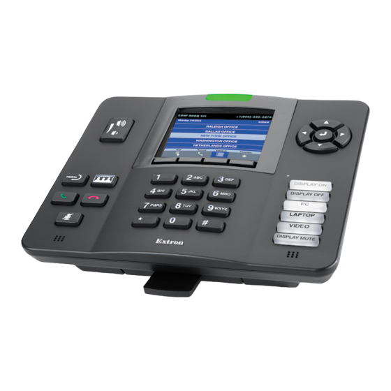
Page 10: Panel Features
• • Rear Panel Features Front Panel Features The CCI Pro 700 comes with installed buttons for common functions (see Button Replacement on page 22 for information on changing the buttons). However, button functions are not assigned until configured in Global Configurator Plus and Professional (see the Global Configurator Help file). -
Page 11: Rear Panel Features
Rear Panel Access To access the rear panel, remove the CCI Pro 700 from the base. Firmly hold the base and lift up the tab on the top of the CCI Pro 700 to dislodge the CCI Pro 700 from the base. -
Page 12: Rear Panel Buttons And Connector
A BC LAN and Power over Ethernet (PoE) connector (see page 7) Menu button (see page 8) Reset button and LED (see page 8) Figure 5. Rear Panel Features CCI Pro 700 TouchLink Pro Conference Room Control Interface • Panel Features... - Page 13 Connect a second straight-through cable between the power injector and the CCI Pro 700 to carry the network information and 48 VDC from the power injector to the interface. Connect the IEC power cord to a convenient 100 VAC to 240 VAC, 50-60 Hz power source.
- Page 14 ATTENTION: • The CCI Pro 700 is intended for connection to a Power over Ethernet circuit for intra-building use only and are considered to be part of a Network Environment 0 per IEC TR62101. • Le CCI Pro 700 est conçu pour une connexion à un circuit PoE pour une utilisation intérieure seulement et est considéré...
-
Page 15: Cable Routing
Connect the cable to the LAN and PoE connector (see figure on page 6) Route the cable around the guides of the CCI Pro 700 as shown in figure 9. Figure 9. Routing Cable along the Rear Panel Reattach the CCI Pro 700 to the base. -
Page 16: Setup Menu
To enter letters, note the groups of letters on the keypad buttons and press the button repeatedly until the desired letter appears on the LCD screen. CCI Pro 700 TouchLink Pro Conference Room Control Interface • Setup Menu... -
Page 17: Setup Menu System
Setup Menu System The setup menu contains four submenus for configuring the CCI Pro 700 and one to display information about the CCI Pro 700. The available submenus include: • Status Submenu • Network Submenu • Display Submenu • Audio Submenu Advanced Submenu •... -
Page 18: Network Submenu
Navigation Keypad enter values. The range is 0.0.0.0 to 255.255.255.255 (the default is 0.0.0.0). NOTE: Use the button to enter a period ( ) character. * Keypad CCI Pro 700 TouchLink Pro Conference Room Control Interface • Setup Menu... -
Page 19: Display Submenu
To deactivate Sleep mode after it has been activated, perform one of the following: Press a button on the front panel. • With Wake on Motion mode enabled, make a motion near the device. • CCI Pro 700 TouchLink Pro Conference Room Control Interface • Setup Menu... -
Page 20: Audio Submenu
Sound volume — Press the ◄ and ► • buttons to set the audio level of Navigation playback audio. The sound volume range is 0-100% of the master volume. The default value is 80%. CCI Pro 700 TouchLink Pro Conference Room Control Interface • Setup Menu... -
Page 21: Advanced Submenu
PIN number (see Keypad figure 16). Figure 16. Enter New Menu Pin Submenu • Controller IP address — Displays the IP address of the connected controller. CCI Pro 700 TouchLink Pro Conference Room Control Interface • Setup Menu... - Page 22 Revision date — Displays the date the GUI Designer file was last modified in the format: MM/dd/yyyy hh:mm:ss, where MM is the month and mm is the minutes. • Project resolution — Displays the resolution in the format: [width]x[height]. CCI Pro 700 TouchLink Pro Conference Room Control Interface • Setup Menu...
-
Page 23: Configuration Software
Software Descriptions GUI Designer Use the GUI Designer software to design the LCD screen layout for the CCI Pro 700. See the GUI Designer Help file for more information about the software. The LCD screen is 3.5” with a resolution of 320x240. -
Page 24: Software Overview
Software Overview To design a graphical user interface (GUI) for the CCI Pro 700 and configure button functions, perform the following steps: Download and install GUI Designer and Global Configurator Plus and Professional to a computer connected to the same network as the control processor and CCI Pro 700... -
Page 25: Software Installation
Figure 20. CCI Pro 700 Web Page Web Page Access In a Web browser, enter the device IP address. If the CCI Pro 700 is password-protected, enter the interface username and password. NOTE: The interface has the following default login credentials: •... -
Page 26: License Information
To view a copy of a listed package license, click the link in the column of the License desired package. A copy of the package license opens in a separate page. Click the button to close the dialog box. Close CCI Pro 700 TouchLink Pro Conference Room Control Interface • Configuration Software... -
Page 27: Firmware Updates
Firmware Updates To upload firmware to the CCI Pro 700, use the internal Web page or the Toolbelt software. For information on Toolbelt, see the Toolbelt Help file. To upload firmware to the CCI Pro 700 with the internal Web page, perform the following:... -
Page 28: Reference Information
4) and Mode buttons (see figure on page 4) come installed in the CCI Pro 700, but any or all of these buttons can be replaced if they are assigned different functions when the device is customized. The interface ships with the following default set of buttons installed: (Mode buttons) •... - Page 29 Reconnect the front panel with the same seven screws removed in step 3. Reconnect the power to the CCI Pro 700. Reattach the CCI Pro 700 to the base. CCI Pro 700 TouchLink Pro Conference Room Control Interface • Reference Information...
-
Page 30: Reset Modes
(<1 second). values including IP settings and real-time adjustments. All user-loaded files are deleted. • • The Reset LED blinks four times in quick succession during the reset. CCI Pro 700 TouchLink Pro Conference Room Control Interface • Reference Information... -
Page 31: Firmware Download
A Release Notes file, giving information on what has changed in the new firmware version, and a set of instructions for updating the firmware are also loaded. Firmware Updates on page 21 for firmware installation considerations. CCI Pro 700 TouchLink Pro Conference Room Control Interface • Reference Information... - Page 32 Extron Electronics makes no further warranties either expressed or implied with respect to the product and its quality, performance, merchantability, or fitness for any particular use. In no event will Extron Electronics be liable for direct, indirect, or consequential damages resulting from any defect in this product even if Extron Electronics has been advised of such damage.
Need help?
Do you have a question about the CCI Pro 700 and is the answer not in the manual?
Questions and answers