
Related Manuals for REMEHA Gas 310 ECO PRO-285


Summary of Contents for REMEHA Gas 310 ECO PRO-285
- Page 1 Great Britain Gas 310 ECO PRO - Gas 610 ECO PRO Installation, User and Service Manual 125467-05...
-
Page 2: Ec Declaration Of Conformity
EC declaration of conformity The device complies with the standard type described in the EG declaration of conformity. It was manufactured and commissioned in accordance with European directives. The original declaration of conformity is available from the manufacturer. -
Page 3: Table Of Contents
Contents Introduction ....................6 Symbols used ............6 Abbreviations ............6 Liabilities ...............7 1.3.1 Manufacturer’s liability ..........7 1.3.2 Installer’s liability .............7 1.3.3 User’s liability ............7 Safety instructions and recommendations ..........9 Safety instructions ..........9 Recommendations ..........9 Technical description ................11 General description ..........11 Homologations ............11 3.2.1 Certifications ............11 3.2.2... - Page 4 Contents 4.3.2 Location of the boiler ..........21 4.3.3 Main dimensions ...........26 Hydraulic connections ........28 4.4.1 Flushing the system ..........28 4.4.2 Connection of the heating circuit ......28 4.4.3 Connecting the condensate discharge pipe ..29 Gas connection ...........30 Connections for the air and exhaust pipes ..............30 4.6.1 Classification ............31...
- Page 5 5.4.2 Setting the air/gas ratio (Part load) ......55 Checks and adjustments after commissioning ...........56 5.5.1 Finalizing work ............56 Reading out measured values ......56 5.6.1 Reading the various current values .......56 Changing the settings ........57 Switching off the boiler ................58 Installation shutdown .........58 Antifreeze protection ..........58 Checking and maintenance ..............59 General ..............59...
- Page 6 Contents 8.1.4 Error memory ............75 Spare parts ....................76 General ..............76 Checklists ....................77 10.1 Checklist for commissioning ......77 10.2 Checklist for periodic inspection and maintenance ............78 160514 - 125467-05...
- Page 7 160514 - 125467-05...
-
Page 8: Introduction
1. Introduction Gas 310 ECO PRO - Gas 610 ECO PRO Introduction Symbols used In these instructions, various danger levels are employed to draw the user’s attention to particular information. In so doing, we wish to safeguard the user’s safety, obviate hazards and guarantee correct operation of the appliance. -
Page 9: Liabilities
Gas 310 ECO PRO - Gas 610 ECO PRO 1. Introduction Liabilities 1.3.1. Manufacturer’s liability Our products are manufactured in compliance with the requirements of the various applicable European Directives. They are therefore delivered with [ marking and all relevant documentation. In the interest of customers, we are continuously endeavouring to make improvements in product quality. - Page 10 1. Introduction Gas 310 ECO PRO - Gas 610 ECO PRO This appliance is not intended to be used by persons (including children) whose physcial, sensory or mental capacity is impaired or persons with no experience or knowledge, unless they have the benefit, through the intermediary of a person responsible for their safety, of supervision or prior instructions regarding use of the appliance.
-
Page 11: Safety Instructions And Recommendations
Gas 310 ECO PRO - Gas 610 ECO PRO 2. Safety instructions and recommendations Safety instructions and recommendations Safety instructions DANGER If you smell gas: Do not use a naked flame, do not smoke, do not operate electrical contacts or switches ( doorbell, light, motor, lift, etc..). - Page 12 Immediately replace damaged or illegible instructions and warning stickers. Modifications Modifications may only be made to the boiler after the written permission of Remeha to do so. 160514 - 125467-05...
-
Page 13: Technical Description
4 Separable for assembly in boiler room. 4 HMI Gas 310/610 ECO PRO control panel. Boiler type: 4 Type Gas 310 ECO PRO-285 4 Type Gas 310 ECO PRO-355 4 Type Gas 310 ECO PRO-430 4 Type Gas 310 ECO PRO-500... -
Page 14: Equipment Categories
3. Technical description Gas 310 ECO PRO - Gas 610 ECO PRO 3.2.2. Equipment categories Gas category Gas type Connection pressure (mbar) Gas H (G20) 20 The boiler is preset in the factory to operate on natural gas G20 (Gas 3.2.3. -
Page 15: Main Parts
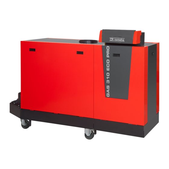
Gas 310 ECO PRO - Gas 610 ECO PRO 3. Technical description Main parts 3.3.1. Boiler type Gas 310 ECO PRO T004014-E Return sensor Flow connection Air differential pressure switch Gas filter Flue gas discharge pipe Type plate Return connection Siphon Outlet for measuring combustion gases Transport wheels... -
Page 16: Boiler Type Gas 610 Eco Pro
3. Technical description Gas 310 ECO PRO - Gas 610 ECO PRO 3.3.2. Boiler type Gas 610 ECO PRO T004015-G Return sensor Flow connection Air differential pressure switch Gas filter Flue gas discharge pipe Type plate Return connection Siphon Outlet for measuring combustion gases Transport wheels Flue gas thermostat (Accessory) Jacking bolt... -
Page 17: Regulation Of The Water Temperature
Gas 310 ECO PRO - Gas 610 ECO PRO 3. Technical description ¼For more information on controlling a modulating pump, See paragraph: "Electrical connections", page 36. Parameters p43 and p44 are used to modify the pump settings. ¼See the Installation and service manual HMI GAS 310/610 ECO PRO for comprehensive operating instructions. - Page 18 3. Technical description Gas 310 ECO PRO - Gas 610 ECO PRO Boiler type GAS 310 ECO PRO Unit General Number of sections EC indentification no. 0063CL3613 Input control Adjustable Modulating, Start/Stop, 0 - 10 V minimum Nominal output (Pn) (80/60 °C) maximum Nominal output (Pn)
-
Page 19: Boiler Type Gas 610 Eco Pro
Gas 310 ECO PRO - Gas 610 ECO PRO 3. Technical description Boiler type GAS 310 ECO PRO Unit Power consumption - Part load maximum Power consumption - Standby maximum Electrical protection index Other characteristics Weight (empty) Total dB(A) Acoustic level at 1 metre Ambient temperature maximum °C... - Page 20 3. Technical description Gas 310 ECO PRO - Gas 610 ECO PRO Boiler type GAS 610 ECO PRO Unit 1000 1150 1300 Water content Water operating pressure minimum Water operating pressure (PMS) maximum Water temperature maximum °C minimum maximum Operating temperature °C Factory setting mbar...
-
Page 21: Installation
Gas 310 ECO PRO - Gas 610 ECO PRO 4. Installation Installation Regulations governing installation WARNING Installation of the appliance must be done by a qualified engineer in accordance with prevailing local and national regulations. The engineer must be Gas Safe registered and have the correct ACS qualifications. -
Page 22: Installation Options
4. Installation Gas 310 ECO PRO - Gas 610 ECO PRO Installation options 4.3.1. Transport For Gas 610 ECO PRO boilers: The features and instructions described are for each boiler module. Boiler type L (mm) Gas 310 ECO PRO 1920 1789 2230 The boiler is supplied fully assembled on a pallet. -
Page 23: Location Of The Boiler
Gas 310 ECO PRO - Gas 610 ECO PRO 4. Installation 4.3.2. Location of the boiler n Boiler type Gas 310 ECO PRO Left version Right version Inspection hatch (Service side) The service side with the inspection hatch on the heat exchanger is considered to be the front of the boiler. - Page 24 4. Installation Gas 310 ECO PRO - Gas 610 ECO PRO C + 1100* 800* C + 600 C + 1100* 800* C + 600 C + C1 + 2200* 800* 800* C + C1 + 1200 T003499-C Spacing required if this is operating side. ¼For the dimensions of C/C1, see paragraph: "Main dimensions", page 26 A technical clearance of at least 80 cm is required at the front (service...
- Page 25 Gas 310 ECO PRO - Gas 610 ECO PRO 4. Installation n Boiler type Gas 610 ECO PRO The boiler is not available with a choice between ’left-hand’ and ’right- hand’ versions. The control panel is on the front as standard, but can easily be rotated so that it is on the short side.
- Page 26 4. Installation Gas 310 ECO PRO - Gas 610 ECO PRO C + 1100 3050 1450 C + 600 T003768-F ¼For the dimensions of C, see paragraph: "Main dimensions", page 26. A technical clearance of at least 80 cm is required at the front (service side) of the boiler.
- Page 27 Gas 310 ECO PRO - Gas 610 ECO PRO 4. Installation n Rotate instrument panel The control panel is on the front as standard, but can easily be rotated so that it is on the short side. 1. Unscrew the 4 lateral holding screws in the control panel. 2.
-
Page 28: Main Dimensions
4. Installation Gas 310 ECO PRO - Gas 610 ECO PRO 4.3.3. Main dimensions n Boiler type Gas 310 ECO PRO Ø 250 Ø 250 T003472-H Gas 310 ECO PRO A (mm) B (mm) C (mm) L (mm) Symbol Fittings 1833 1635 1862... - Page 29 Gas 310 ECO PRO - Gas 610 ECO PRO 4. Installation n Boiler type Gas 610 ECO PRO T003766-J Gas 610 ECO PRO A (mm) B (mm) C (mm) L (mm) Symbol Fittings 1833 1582 1862 1490 Heating circuit flow, Flange NW 80 (DIN 2576) 1833 1582 1862...
-
Page 30: Hydraulic Connections
4. Installation Gas 310 ECO PRO - Gas 610 ECO PRO Hydraulic connections 4.4.1. Flushing the system The installation must be cleaned and flushed according to BS 7593 (2006). Installing the boiler in new installations (installations less than 6 months old) 4 Clean the installation with a universal cleaner to eliminate debris from the system (copper, hemp, flux). -
Page 31: Connecting The Condensate Discharge Pipe
Gas 310 ECO PRO - Gas 610 ECO PRO 4. Installation The flow pipe is fitted with the following components: Tube pocket for a temperature sensor for an external control (½"). Vent device (⅛"). Connection for safety valve (1½"). Pressure gauge (½"). Flow sensor (M6). -
Page 32: Gas Connection
4. Installation Gas 310 ECO PRO - Gas 610 ECO PRO Gas connection For the connection(s) of the boiler Gas 610 ECO PRO: The features and instructions described are for each boiler module. WARNING Close the main gas valve before starting work on the gas pipes. -
Page 33: Classification
Gas 310 ECO PRO - Gas 610 ECO PRO 4. Installation 4.6.1. Classification The table specifies this classification in detail according to [. Type Execution Description Open flue Without fire-stop approval. B23P Exhaust of combustion gases above the roof. Air in the installation room. Open flue Without fire-stop approval. -
Page 34: Lengths Of The Air/Flue Gas Pipes
4. Installation Gas 310 ECO PRO - Gas 610 ECO PRO 4.6.3. Lengths of the air/flue gas pipes To define the maximum final length, you must deduct the pipe length in accordance with the reduction table. The boiler is also suitable for longer chimney lengths with diameters other than those indicated in the table. - Page 35 Gas 310 ECO PRO - Gas 610 ECO PRO 4. Installation Gas 610 ECO Chimney length for the open flue version Maximum length (L) Boiler type with a Ø of 250 with a Ø of 300 with a Ø of 350 50 m 50 m 50 m...
- Page 36 4. Installation Gas 310 ECO PRO - Gas 610 ECO PRO n Connection in areas of different pressure ( C53, C83) Combustion air supply and combustion gas discharge are possible in various pressure zones, semi-CLV systems. The maximum permissible difference in height between the combustion air supply and the combustion gas discharge is 36 m.
-
Page 37: Additional Directives
Gas 310 ECO PRO - Gas 610 ECO PRO 4. Installation 4.6.4. Additional Directives 4 Please refer to the manufacturer’s instructions for the material in question when installing the flue gas discharge and air supply materials. If the flue gas discharge and air supply materials are not installed according to the instructions (e.g. -
Page 38: Connection Of The Air Intake Pipe
4. Installation Gas 310 ECO PRO - Gas 610 ECO PRO 2. Fit together the combustion gas exhaust pipes, without welding. The pipes must allow no leakage of flue gases and be resistant to corrosion. Connect the pipes together without stress between the sections. -
Page 39: Control Unit
Gas 310 ECO PRO - Gas 610 ECO PRO 4. Installation 4.7.1. Control unit Pre-wired in the boiler Three wired power cord The boiler has a detection phase. The boiler is fully pre-wired. The boiler is suitable for a 230 V / 50 Hz power supply with live/neutral/ earth. -
Page 40: Recommendations
4. Installation Gas 310 ECO PRO - Gas 610 ECO PRO 4 On/Off setting: where the heat output modulates between the minimum and maximum value based on the flow temperature set in the boiler. ¼The standard control PCB (PCU-06) can be extended with the following, for example: "Accessories", page 19 4.7.2. - Page 41 Gas 310 ECO PRO - Gas 610 ECO PRO 4. Installation A clearance of 20 cm is required above the instrument panel to allow the front cover to open fully. Bear this in mind when installing cable ducts. Access to the connector block: 1.
-
Page 42: Connecting The On/Off Control
4. Installation Gas 310 ECO PRO - Gas 610 ECO PRO 4.7.4. Connecting the on/off control The boiler can be controlled with an on/off controller. Connect the controller to the ON/OFF-OT connector. (It does not matter which wire is connected to which cable clamp). Mains ON/OFF PUMP... -
Page 43: Release Input
Gas 310 ECO PRO - Gas 610 ECO PRO 4. Installation 4.7.7. Release input The boiler has a release input (Normally open contact). If this contact is closed when there is a heat demand, the burner will go into shutdown after a waiting time. This input can be used in combination with the limit switches on flue gas dampers, hydraulic shutter valves, etc.. -
Page 44: Connection Possibilities For The Pcb (Scu- S05)
4. Installation Gas 310 ECO PRO - Gas 610 ECO PRO 4.7.10. Connection possibilities for the PCB (SCU- S05) SCU-S05 Pump Status Status 0-10 Ctrl Pump Nc C Nc C Tout Nc C Nc C Tout T003684-C ¼To set the parameter selected: See the Installation and service manual HMI Gas 310/610 ECO PRO for comprehensive operating instructions. - Page 45 Gas 310 ECO PRO - Gas 610 ECO PRO 4. Installation n Connecting a shunt pump (Pump) If required, a shunt pump may also be installed on the terminals Pump Pump of the connector. Only an on/off pump can be controlled. The Pump pump is activated during lock outs 5t:9 (5v:4,5 and 6).
- Page 46 4. Installation Gas 310 ECO PRO - Gas 610 ECO PRO Control of 0 - 10 V Grundfos system pump Pump regime Minimum pump speed Maximum pump speed Nominal set-point Output signal (V) 1 2 3 4 5 6 7 8 9 T003803-B Output signal (V) Description Pump on (Minimum pump speed)
- Page 47 Gas 310 ECO PRO - Gas 610 ECO PRO 4. Installation The 0 - 10 V signal controls the boiler output. The minimum and maximum values are limited. The minimum output is linked to the boiler’s modulation depth. The output varies between the minimum and maximum value on the basis of the value determined by the controller.
- Page 48 4. Installation Gas 310 ECO PRO - Gas 610 ECO PRO Pressure switch minimum 10 mbar 10 mbar 10 mbar n Gas valve leak proving system (Vps) The gas leakage control checks and controls the safety valves on the gas block. The test takes place before the boiler starts up. In the event of a leak in the gas block, the boiler will lock out.
-
Page 49: Electrical Diagram
Gas 310 ECO PRO - Gas 610 ECO PRO 4. Installation Electrical diagram PCU-06 Mains Pump On / Off 1 2 3 2 3 4 5 6 7 8 10 11 1 10 1 2 3 4 1 2 3 1 2 3 4 5 6 1 2 3 4 SU-01... -
Page 50: Water Treatment
WARNING Do not add chemical products to the central heating water without consulting Remeha. For example: antifreeze, water softeners, products to increase or reduce the pH value, chemical additives and/or inhibitors. These may cause faults in the boiler and damage the heat exchanger. -
Page 51: Filling The System
Gas 310 ECO PRO - Gas 610 ECO PRO 4. Installation 4.9.3. Filling the system 1. Fill the system with clean tap water. The boilers can function at an operating pressure of between 0.8 - 7 bar. 2. Check the tightness of the water connections. If the water pressure is lower than 0.8 bar, the symbol e will appear. -
Page 52: Commissioning
5. Commissioning Gas 310 ECO PRO - Gas 610 ECO PRO Commissioning Control panel For operation of the boiler Gas 610 ECO PRO: Each module has its own instrument panel. ¼See the Installation and service manual HMI GAS 310/610 ECO PRO for comprehensive operating instructions. -
Page 53: Check Points Before Commissioning
Gas 310 ECO PRO - Gas 610 ECO PRO 5. Commissioning Defect: Antifreeze protection: Boiler indicates a fault. This can be seen from the e code Boiler is running in frost protection mode. and red display. Hour counter menu: Burner level: Readout of the operating hours, number of successful starts Output level . -
Page 54: Gas Circuit
5. Commissioning Gas 310 ECO PRO - Gas 610 ECO PRO 5.2.2. Gas circuit WARNING Ensure that the boiler is switched off. 1. Open the main gas supply. 2. Remove the casings on the inspection side. 3. Measure the inlet gas pressure via the measuring point C on the gas pipe. -
Page 55: Gas Settings
Gas 310 ECO PRO - Gas 610 ECO PRO 5. Commissioning 3. The start-up cycle begins and cannot be interrupted. During the start-up cycle, the display shows the following information: A short test where all segments of the display are visible. fK[xx : Software version pK[xx : Parameter version The version numbers are displayed alternately. -
Page 56: Setting The Air/Gas Ratio (Full Load)
5. Commissioning Gas 310 ECO PRO - Gas 610 ECO PRO 5.4.1. Setting the air/gas ratio (Full load) For checking and/or setting the boiler Gas 610 ECO PRO: The features and instructions described are for each boiler module. Make sure that the other boiler module is ºCºFh ºC barPsi... -
Page 57: Setting The Air/Gas Ratio (Part Load)
Gas 310 ECO PRO - Gas 610 ECO PRO 5. Commissioning 5.4.2. Setting the air/gas ratio (Part load) For checking and/or setting the boiler Gas 610 ECO PRO: The features and instructions described are for each ºCºFh boiler module. Make sure that the other boiler module is ºC barPsi kWµA... -
Page 58: Checks And Adjustments After Commissioning
5. Commissioning Gas 310 ECO PRO - Gas 610 ECO PRO Checks and adjustments after commissioning 5.5.1. Finalizing work 1. Remove the measuring equipment. 2. Put the flue gas sampling plug back in place. 3. If installed: Check the setting of the minimum gas pressure switch Gps. -
Page 59: Changing The Settings
Gas 310 ECO PRO - Gas 610 ECO PRO 5. Commissioning 4 t1 = Flow temperature (°C). 4 t" = Return temperature (°C). 4 t4 = Outside temperature (°C) Only with an outside temperature sensor (Accessory). 4 t6 = Exchanger temperature (°C). 4 5p = Internal set point (°C). -
Page 60: Switching Off The Boiler
6. Switching off the boiler Gas 310 ECO PRO - Gas 610 ECO PRO Switching off the boiler Installation shutdown If the central heating system is not used for a long period, we recommend switching the boiler off. 4 Switch the On/Off switch to Off. 4 Switch off the boiler electrical power supply. -
Page 61: Checking And Maintenance
Gas 310 ECO PRO - Gas 610 ECO PRO 7. Checking and maintenance Checking and maintenance General The cast aluminium/silicon heat exchanger forms the heart of the boiler. When combined with the special geometric shape, the flue gas pollution remains limited. At the top of the heat exchanger, the space between the pins of the heated surface on the flue gas side is slightly larger than further down. -
Page 62: Checking The Hydraulic Pressure
7. Checking and maintenance Gas 310 ECO PRO - Gas 610 ECO PRO 10.Check the air pressure differential switch PS. 11.If installed: Check the gas leakage control VPS. 12.If installed: Check the minimum gas pressure switch Gps. Preparation First heat the boiler on high for about 5 minutes (return temperature 65ºC) to dry the heat exchanger on the flue gas side. -
Page 63: Checking The Gas Filter For Pollution
Gas 310 ECO PRO - Gas 610 ECO PRO 7. Checking and maintenance 7.2.5. Checking the gas filter for pollution The gas block on the boiler is fitted with a gas filter as standard. Check this for pollution. 1. Set the boiler to full load. 2. -
Page 64: Check The Air Supply Hose
7. Checking and maintenance Gas 310 ECO PRO - Gas 610 ECO PRO 8. Put the flue gas sampling plug back in place. 7.2.7. Check the air supply hose 1. Disconnect the pipe on the air box side by loosening the bayonet fitting. -
Page 65: Check The Air Pressure Differential Switch Ps
Gas 310 ECO PRO - Gas 610 ECO PRO 7. Checking and maintenance 7.2.10. Check the air pressure differential switch Check the air pressure differential switch + 1. Switch the boiler off. 2. Disconnect the silicon hose on the + side (P1) of the air pressure differential switch. -
Page 66: Check The Gas Leakage Control Vps
7. Checking and maintenance Gas 310 ECO PRO - Gas 610 ECO PRO 7.2.11. Check the gas leakage control VPS A - Leak test 1. Switch the boiler off. 2. Close the boiler gas cock. 3. Remove the pressure from the gas pipe by unscrewing the screw in measuring point P1. - Page 67 Gas 310 ECO PRO - Gas 610 ECO PRO 7. Checking and maintenance B - Check the switch value 1. "Remove the pressure from the gas block; to do so remove the hose connected to measuring point 3 of the gas block" (On the opposite side of the VPS pressure switch).
-
Page 68: Check The Minimum Gas Pressure Switch Gps
7. Checking and maintenance Gas 310 ECO PRO - Gas 610 ECO PRO 7.2.12. Check the minimum gas pressure switch 1. Switch the boiler off. 2. Open the screw in measuring point 2 of the gas block. 3. Connect a pressure gauge to measuring point 2 of the gas block. 4. -
Page 69: Clean The Fan And The Venturi
Gas 310 ECO PRO - Gas 610 ECO PRO 7. Checking and maintenance DANGER Disconnect the appliance’s electricity supply. Shut off the gas supply. We recommend carrying out the specific maintenance activities in the following order: 1. Clean the fan and the venturi. 2. -
Page 70: Clean And Inspect The Non-Return Valve
7. Checking and maintenance Gas 310 ECO PRO - Gas 610 ECO PRO 7.3.2. Clean and inspect the non-return valve The non return valve must be replaced if it is faulty. 1. Remove the electrical connections from the fan. Push the safety slides on both sides of the power plug right to the back (You could use a small screwdriver for example). -
Page 71: Cleaning The Gas Filter
Gas 310 ECO PRO - Gas 610 ECO PRO 7. Checking and maintenance 7.3.4. Cleaning the gas filter The 5 to 9 section boilers are supplied with a different gas block from the 10 section boiler. 1. Remove the gas filter. 2. -
Page 72: Cleaning The Burner
7. Checking and maintenance Gas 310 ECO PRO - Gas 610 ECO PRO 7.3.5. Cleaning the burner 1. Unscrew the nuts from the adapter: Remove the adapter. 2. Lift the burner out of the heat exchanger. 3. Check the burner and, if necessary, clean without touching it (e.g. with compressed air between 2 and 5 bars: respect a minimum distance of 1 cm from the surface of the burner). -
Page 73: Checking The Heat Exchanger
Gas 310 ECO PRO - Gas 610 ECO PRO 7. Checking and maintenance 7.3.7. Checking the heat exchanger 1. Unscrew the nuts from the inspection hatch on the heat exchanger. 2. Take the inspection hatch off the heat exchanger and remove the insulation cloth. -
Page 74: Cleaning The Condensate Collector
7. Checking and maintenance Gas 310 ECO PRO - Gas 610 ECO PRO 7.3.8. Cleaning the condensate collector 1. Remove both sealing caps from the condensate collector. (In front of and behind the flue gas discharge connection). 2. Thoroughly clean the condensate collector with water. Rinse each side of the condensate collector for at least 5 minutes with the largest possible water flow. -
Page 75: Assembling The Boiler
Gas 310 ECO PRO - Gas 610 ECO PRO 7. Checking and maintenance 7.3.10. Assembling the boiler 1. Fit the burner. The burner has 2 holes at the front. Position it on the 2 support pins at the burner opening. 2. -
Page 76: Troubleshooting
8. Troubleshooting Gas 310 ECO PRO - Gas 610 ECO PRO Troubleshooting Shutdowns and lock-outs For operation of the boiler Gas 610 ECO PRO: The features and instructions described are for each boiler module. 8.1.1. General The boiler is fitted with an electronic regulation and control unit. The heart of the control system is a microprocessor, the Comfort ©... -
Page 77: Error Memory
Gas 310 ECO PRO - Gas 610 ECO PRO 8. Troubleshooting The boiler can only start operating again once the causes of the lock-out have been rectified and after pressing the J key 8.1.4. Error memory The boiler control is equipped with an error memory. The last 10 errors encountered are recorded in this memory. -
Page 78: Spare Parts
9. Spare parts Gas 310 ECO PRO - Gas 610 ECO PRO Spare parts General When it is observed subsequent to inspection or maintenance work that a component in the boiler needs to be replaced, use only original spare parts or recommended spare parts and equipment. Send the component to be replaced to your supplier’s Returned Goods Department if the component in queston is under warranty (see general terms and conditions of sale and delivery). -
Page 79: 10 Checklists
Gas 310 ECO PRO - Gas 610 ECO PRO 10. Checklists 10 Checklists 10.1 Checklist for commissioning No. Work to be undertaken for commissioning Confirmation / Measured values Filling the central heating system with water and checking the water pressure Fill the siphon with water Vent the air in the heating system Checking the water-side connections for tightness... -
Page 80: 10.2 Checklist For Periodic Inspection And Maintenance
10. Checklists Gas 310 ECO PRO - Gas 610 ECO PRO 10.2 Checklist for periodic inspection and maintenance No. Inspection and/or service activities Confirmation and date Checking the hydraulic pressure Checking the ionization current Check the water quality Checking the air supply connections and flue gas discharge connections Checking the gas filter for pollution Checking combustion (CO... - Page 81 Gas 310 ECO PRO - Gas 610 ECO PRO 10. Checklists 160514 - 125467-05...
- Page 82 10. Checklists Gas 310 ECO PRO - Gas 610 ECO PRO 160514 - 125467-05...
- Page 84 Remeha Commercial UK - Part of the BDR THERMEA Remeha House Molly Millars Lane Wokingham Berks RQ41 2QP After Sales Tel: 01189743076 Technical Enquires: 01189743067 Internet: www.remeha.co.uk © Copyright All technical and technological information contained in these technical instructions, as well as any drawings and technical descriptions supplied, remain our property and shall not be multiplied without our prior consent in writing.
Need help?
Do you have a question about the Gas 310 ECO PRO-285 and is the answer not in the manual?
Questions and answers