Table of Contents
Advertisement
Advertisement
Table of Contents

Related Manuals for Otto Bock B-Series


Summary of Contents for Otto Bock B-Series
- Page 1 B-Series Service manual...
-
Page 2: Table Of Contents
Replacing the drive motors ........................ 29 4.9.5 Replacing the drive wheel swing arms ....................30 4.9.6 Installed position of the spacers on the drive ..................31 4.9.7 Replacing the anti-tipper wheel ......................32 4.9.8 Replacing the anti-tipper ........................32 2 | Ottobock B-Series... - Page 3 Replacing the clothing protector ......................67 4.17 Legrests ............................68 4.17.1 Replacing the legrest holder ......................68 4.18 Lighting ............................68 4.18.1 Replacing the lighting ........................68 4.18.2 Replacing the fuse for the lighting ...................... 70 B-Series Ottobock | 3...
- Page 4 Profile-specific control parameters ..................... 93 7.4.5 Latched drive parameters ........................95 7.4.6 Seat parameters ..........................95 Technical data ..............................96 Appendixes ..............................96 Torque values of the screw connections ....................96 Battery circuit diagram ........................96 Maintenance schedule ........................97 4 | Ottobock B-Series...
-
Page 5: Introduction
Use the maintenance schedule (checklist) as a template for making copies. Retain completed maintenance sche- dules and provide the user with a copy. Instructions for use (qualified personnel) Instructions for use (user) B-Series 647G2000 647G2001 Support Your national Ottobock team will be happy to answer any technical questions. The contact addresses and telephone numbers can be found on the back inside cover of the service manual. -
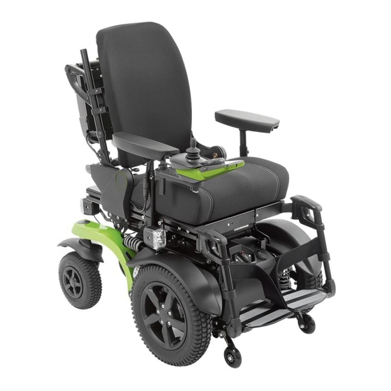
Page 6: Product Overview
10 Anti-tipper 20 Control panel Safety instructions Explanation of warning symbols Warning regarding possible serious risks of accident or injury. WARNING Warning regarding possible risks of accident or injury. CAUTION Warning regarding possible technical damage. NOTICE 6 | Ottobock B-Series... -
Page 7: General Safety Instructions
When using lifting platforms or an assembly stand, ensure that the power wheelchair is centred on the sup- porting surface and that no parts protrude into the danger zone. B-Series Ottobock | 7... -
Page 8: Safety Instructions For Service And Maintenance Tasks
Seite 96. CAUTION Re-use of self-locking nuts Tipping over, falling of the user due to unintended loosening of the screw connections f Always replace self-locking nuts with new self-locking nuts after disassembly. 8 | Ottobock B-Series... -
Page 9: Transport And Storage
Ensure that the power wheelchair is centred on the lifting platform. None of the power wheelchair components, such as the anti-tipper or other parts, are allowed to be in the danger zone. The size of the wheelchair can be reduced for transport (see Fig. 2). B-Series Ottobock | 9... -
Page 10: Storage
If new screws or nuts with a thread lock are not available, use a medium-strength liquid thread locking compound (such as Loctite 241 or Euro Lock A24.20). 10 | Ottobock B-Series... -
Page 11: Instructions For Adjustment
Always secure a jacked up wheelchair against tipping over with the active support of a helper when the seat is folded up. Always fold down the seat before jacking the wheelchair up or down. B-Series Ottobock | 11... -
Page 12: Operating The Seat Height And Seat Tilt
Deactivating the main fuse 1) Press the pushbutton (see Fig. 3/4, item 2) until the reset lever flips up at an angle. 2) The main fuse is deactivated (see Fig. 4). The internal power supply is disconnected. 12 | Ottobock B-Series... -
Page 13: Folding The Seat Up/Down
2) Release the locking bolt and carefully lower the seat onto the support bolts on the front frame of the mobility base. 3) Screw in the support bolts on both sides and firmly tighten them (see Fig. 5, item 1). B-Series Ottobock | 13... -
Page 14: Trim Components On The Mobility Base
Installing the battery cover 1) Put on the battery cover (see Fig. 8). The 2 mounting clips on the battery cover engage securely in the cover when positioned correctly. 2) Fold down the seat (see Seite 13). 14 | Ottobock B-Series... -
Page 15: Replacing The Front Cover
Prerequisites: Optional: Move the seat to the lowest seat height (see Seite 12). Switch off the control unit and deactivate the main fuse (see Seite 12). If necessary: Remove the legrests. f Tools: Allen wrench size 3 B-Series Ottobock | 15... - Page 16 4) Insert and firmly tighten the 2 screws in the rear cover (see Fig. 12, item 1). 5) Fold up the seat (see Seite 13). 6) Attach the battery cover (see Seite 14). 7) Fold down the seat (see Seite 13). 16 | Ottobock B-Series...
-
Page 17: Batteries And Power Supply
5) Lay the battery cables of the automatic circuit breaker along the other battery cables and secure them with cable attachments (see Fig. 15, item 3). 6) Attach the battery cover (see Seite 14). 7) Fold down the seat (see Seite 13). B-Series Ottobock | 17... -
Page 18: Replacing The Batteries
5) If necessary: Move transverse cables to their original installed position and secure with cable attachments if necessary (see Fig. 17, item 4). 6) Attach the battery cover (see Seite 14). 7) Fold down the seat (see Seite 13). 18 | Ottobock B-Series... -
Page 19: Charging The Batteries
9) Fold up the seat (see Seite 13). 10) Check the fuse of the external charging receptacle and insert it in the fuse holder (see Fig. 19). 11) Attach the battery cover (see Seite 14). 12) Fold down the seat (see Seite 13). B-Series Ottobock | 19... -
Page 20: Replacing The External Power Supply Receptacles
1) Pull out the fuse from the fuse holder (blue) (see Fig. 24, item 1). 2) Check the fuse and replace if necessary. 3) Insert the fuse in its original installed position in the fuse holder (blue) (see Fig. 24, item 1). 20 | Ottobock B-Series... -
Page 21: Control Unit
2) Carefully put on the controller (see Fig. 25, item 3). 3) Insert and firmly tighten the 2 controller screws to 1 Nm (see Fig. 25, item 1). 4) Attach the rear cover (see Seite 15). B-Series Ottobock | 21... -
Page 22: Replacing The Seat Module With Cover (Standard Seat)
5) Remove the seat module with module carrier. 6) If necessary: Remove the seat module from the module carrier. To do so, loosen and remove the 4 screws bet- ween the module carrier and seat module (see Fig. 29, item 1). 22 | Ottobock B-Series... -
Page 23: Replacing Additional Control Modules
1) INFORMATION: Note the installed position of the cable connections being loosened. Disconnect all cables from the control module connection sockets (see item 1). 2) Loosen and remove all screws between the control module and module carrier (see item 2). 3) Remove the control module. B-Series Ottobock | 23... -
Page 24: Replacing The Ten° Control Panel
INFORMATION: Align the retaining plate according to the control panel installation position: Fig. 36 shows the alignment of the retaining plate for installation on the right side of the wheelchair. For ins- tallation on the left side of the wheelchair, rotate the retaining plate by 180°. 24 | Ottobock B-Series... -
Page 25: Replacing The Vr2 Control Panel
3) Insert and firmly tighten the screws between the control panel rail and control panel (see Fig. 37, item 2). 4) Connect the cable of the control panel to the cable extension (see Fig. 37, item 1). B-Series Ottobock | 25... -
Page 26: Replacing The Attendant Control
3) Insert the screw in the bracket on the back tube and firmly tighten it (see Fig. 39, item 1). 4) Position and connect the cable for the attendant control according to its original installed position (see Fig. 38, item 1). 5) Reattach the loosened cable attachments (see Fig. 38, item 2). 26 | Ottobock B-Series... -
Page 27: Drive Unit
2) Place the drive wheel splash guard on the drive wheel swing arm (see Fig. 41, item 2). 3) Insert the 2 upper screws in the drive motor and firmly tighten them to 25 Nm (see Fig. 41, item 1). B-Series Ottobock | 27... -
Page 28: Replacing The Drive Wheel Suspension
3) Carefully guide the drive wheel swing arm upwards. 4) Insert the screw with 1 washer between the suspension and frame and firmly tighten it to 25 Nm (see Fig. 42/43, item 1). 28 | Ottobock B-Series... -
Page 29: Replacing The Drive Motors
3) Insert the 2 upper screws between the drive motor and drive wheel swing arm with 1 washer (optional) each and firmly tighten them to 25 Nm (see Fig. 45, item 1). INFORMATION: If a splash guard is installed, the washers are omitted and replaced by the splash guard. B-Series Ottobock | 29... -
Page 30: Replacing The Drive Wheel Swing Arms
2) Insert the screw with fixing washer into the axle and firmly tighten it to 15 Nm (see Fig. 48, item 1). 3) Install the anti-tipper (see Seite 32). 4) Install the drive wheel suspension between the drive wheel swing arm and frame (see Seite 28). 30 | Ottobock B-Series... -
Page 31: Installed Position Of The Spacers On The Drive
(see Fig. 50, item 1) item 2) Long sleeve outside (see Fig. 51, Between mobility base and drive wheel 493T75=PK107/110/114 item 1), swing arm (Large diameter; Short sleeve inside (see Fig. 51, grey release lever) (see Fig. 52, item 1) item 2) B-Series Ottobock | 31... -
Page 32: Replacing The Anti-Tipper Wheel
INFORMATION: The anti-tipper is spring loaded on a wheelchair with front-wheel drive. In this case, tension the spring of the anti-tipper (see Fig. 55, item 1) when installing the drive wheel suspension. 4) Attach the drive wheel (see Seite 27). 32 | Ottobock B-Series... -
Page 33: Caster Wheels
1) Pry out and remove the 2 cover caps on the ends of the caster wheel axle (see Fig. 57; see Seite 33). 2) Loosen and remove the screw on the caster wheel with its nut and 2 washers (see Fig. 58/59). B-Series Ottobock | 33... -
Page 34: Replacing The Caster Wheel Splash Guard
1) Position the caster wheel splash guard on the caster fork from below. 2) Insert the 2 screws into the splash guard and firmly tighten them (see Fig. 60, item 1). 3) Attach the caster wheel (see Seite 33). 34 | Ottobock B-Series... -
Page 35: Replacing The Caster Fork
8) Attach the caster wheel (see Seite 33). 4.10.5 Replacing the caster wheel bearing set f Prerequisites: Optional: Move the seat to the lowest seat height (see Seite 12). Switch off the control unit and deactivate the main fuse (see Seite 12). B-Series Ottobock | 35... -
Page 36: Replacing The Caster Wheel Swivel Lock
7) Loosen and remove the 2 screws of the control panel with 1 washer each (see Fig. 65, item 1). 8) Remove the control panel for the caster wheel swivel lock from the drive wheel splash guard (see Fig. 65, item 2). 36 | Ottobock B-Series... - Page 37 9) Insert the Bowden cable mounting with 1 screw into the caster wheel swing arm and firmly tighten it (see Fig. 64, item 2). 10) Install the caster fork with splash guard (optional) (see Seite 35). 11) Attach the caster wheel (see Seite 33). B-Series Ottobock | 37...
-
Page 38: Replacing The Track Stabiliser
4) Optional: Attach the bolt of the caster wheel swivel lock to the caster wheel swing arm (see Fig. 64; see Sei- te 36). 5) Install the bearing set (see Seite 35). 6) Install the caster fork with splash guard (optional) (see Seite 35). 7) Attach the caster wheel (see Seite 33). 38 | Ottobock B-Series... -
Page 39: Replacing The Suspension For The Caster Wheel Swing Arm
Tools: Allen wrench size 5; torque wrench with Allen insert size 5; socket wrench extension Removing the rigid element of the caster wheel swing arm 1) Loosen and remove the screw between the rigid element and caster wheel swing arm (see Fig. 72). B-Series Ottobock | 39... -
Page 40: 4.10.10 Replacing The Caster Wheel Swing Arm
5) Optional: Attach the caster wheel swivel lock to the caster wheel swing arm (see Seite 36). 6) Install the caster fork with splash guard (optional) (see Seite 35). 7) Attach the caster wheel (see Seite 33). 40 | Ottobock B-Series... -
Page 41: Changing Tyres
3) Join the 2 pieces of the rim. Precisely align the notches for the valve one on top of the other (see Fig. 75, item 1). 4) Insert the 5 screws on the inside of the rim and firmly tighten them in a crosswise sequence (see Fig. 75/76). 5) Attach the wheel (see Seite 27/Seite 33). B-Series Ottobock | 41... -
Page 42: Selecting And Adjusting The Suspensions
Always adjust the left and right suspension equally and in pairs. f Prerequisites: Switch off the control unit and deactivate the main fuse (see Seite 12). If necessary: Remove the legrests. Jack up the wheelchair (see Seite 11). 42 | Ottobock B-Series... -
Page 43: Curb Climbing Assist And Transport Brackets
3) Insert the 4 screws between the curb climbing assist and adapter plate with 1 washer each and firmly tighten them (see Fig. 79, item 1). 4) Swivel the caster wheel swing arms upwards and install both suspensions/rigid elements (see Seite 39 ff.). 5) Attach both caster wheels (see Seite 33). B-Series Ottobock | 43... -
Page 44: Replacing The Transport Brackets
INFORMATION: With rear-wheel drive, insert the screws into the front bores in the transport shackle (see Fig. 81, item 1). With front-wheel drive, insert the screws into the rear bores in the transport shack- le (see Fig. 81, item 2). 3) Attach the caster wheel (see Seite 33). 44 | Ottobock B-Series... -
Page 45: Seat
4) Position the back evenly using the markings on the seat plate (see Seite 58). 5) Firmly tighten the 2 screws in the bearing plates on both sides to 25 Nm (see Fig. 85, item 1). 6) Install the cover on both bearing plates (see Seite 57). B-Series Ottobock | 45... -
Page 46: Adjusting The Seat Width (Vas Seat)
9) Insert the 2 screws for the seat plate segments into the appropriate slots and firmly tighten them to 4 Nm (see Fig. 88, item 1). 10) Install the seat plate (see Seite 45). 11) Readjust the back upholstery (see Seite 64). 46 | Ottobock B-Series... -
Page 47: Setting The Pre-Tilt / Replacing The Seat Height Adapter
6) Insert the 2 screws into the seat height adapter and firmly tighten them to 25 Nm (see Fig. 89, item 1). 7) Connect the external power supply receptacles and attach the front cover (see Seite 15). 8) Attach the battery cover (see Seite 14). 9) Fold down the seat (see Seite 13). B-Series Ottobock | 47... - Page 48 16) Install all cable connections and cable attachments according to the original installed position (see Fig. 91, item 2/3). 17) Attach the rear cover (see Seite 15). 18) Attach the battery cover (see Seite 14). 19) Fold down the seat (see Seite 13). 20) Check all seat functions. 48 | Ottobock B-Series...
-
Page 49: Replacing The Seat Frame With Seat Brackets (Standard Seat)
2) Carefully insert the seat frame into the seat brackets. 3) Insert the 3 screws with nuts between the seat frame and seat brackets on both sides and firmly tighten them (see Fig. 94, item 1). B-Series Ottobock | 49... -
Page 50: Replacing The Seat Frame (Vas Seat)
4) Install the side panel holders and side panels (see Seite 66). 5) Install the seat plate (see Seite 45). 6) Install the back (see Seite 58). 7) Install the legrest holder (see Seite 68). 50 | Ottobock B-Series... -
Page 51: Replacing The Seat Height Adjustment Actuator
10) Loosen and remove the 2 screws between the top of the frame and the seat height adjustment actuator (see Fig. 102, item 1). 11) INFORMATION: Take note of the installed position of the actuator cable. Remove the seat height adjustment actuator with the actuator cable. Remove or open additional cable attach- ments if necessary. B-Series Ottobock | 51... - Page 52 11) Fold up the seat (see Seite 13). 12) Insert the 2 screws between the bottom of the frame and the seat height adjustment actuator and firmly tighten them (see Fig. 97, item 1). 13) Fold down the seat (see Seite 13). 52 | Ottobock B-Series...
-
Page 53: Replacing And Adjusting The Seat Height Adjustment Sensor
2) Fold up the seat (see Seite 13). 3) Carefully insert the seat height adjustment sensor and position the cable according to its original installed posi- tion. Reattach or close the loosened cable attachments (see Fig. 103, item 2). B-Series Ottobock | 53... - Page 54 5) Firmly tighten the 2 Phillips screws on the seat height adjustment sensor (see Fig. 104/105, item 1). 6) Fold down the seat (see Seite 13). 7) Verify the functionality of the sensor and readjust it if required. 54 | Ottobock B-Series...
-
Page 55: Replacing The Seat Tilt Actuator
5) Position and connect the actuator cable according to its original installed position. INFORMATION: The actuator cable is connected to the seat module or the controller depending on the configuration. 6) Reattach the loosened cable attachments and covers. 7) Attach the seat plate (see Seite 45 ff.). B-Series Ottobock | 55... -
Page 56: Back
3) Insert the bearing screw into the bearing plate and the back and firmly tighten it (see Fig. 108/109, item 1). 4) Fold the back to the rear. 5) Optional: Install the actuator for the power back angle adjustment (see Seite 59). 56 | Ottobock B-Series... -
Page 57: Replacing The Cover For The Bearing Plates (Vas Seat)
4) Loosen and remove the bearing screw (see Fig. 112, item 1). 5) Loosen and remove the 2 screws between the bearing plate and seat bar (see Fig. 112, item 2). 6) Remove the bearing plate. B-Series Ottobock | 57... -
Page 58: Adjusting/Replacing The Back (Standard Seat)
2) Loosen the 2 screws in the bearing plates on both sides (see Fig. 113, item 1). 3) Adjust the back. If necessary, remove the cable attachments along the seat bars (see Fig. 113, item 2). 58 | Ottobock B-Series... -
Page 59: Removing/Installing The Power Back Angle Adjustment (Standard Seat)
Replacing the actuator for the power back angle adjustment (standard seat) f Prerequisites: Switch off the control unit and deactivate the main fuse (see Seite 12). f Tools: Allen wrench size 4; torque wrench with Allen insert size 4 B-Series Ottobock | 59... -
Page 60: Removing/Installing The Manual Back Angle Adjustment (Standard Seat)
2) Rotate the key ring on the release strap out of the eyelet of the locking bolt on both sides (see Fig. 117, item 2). 3) Remove the locking bolt with compression spring from the back tube on both sides. 4) Optional: Install the power back angle adjustment (see Seite 59). 60 | Ottobock B-Series... -
Page 61: Removing/Installing The Power Back Angle Adjustment (Vas Seat)
4 screws of the lower connecting tube and tighten them again after making the adjustment (see Fig. 118, item 3). 3) Insert the 2 screws and nuts into the lower connecting tube and bearing plate on both sides and firmly tighten them (see Fig. 120, item 1). B-Series Ottobock | 61... -
Page 62: Replacing The Actuator For The Power Back Angle Adjustment (Vas Seat)
1) Insert the actuator for the power back angle adjustment into the back and hold it firmly. 2) Insert the screw into the back and the bearing eye of the power back angle adjustment actuator and firmly tighten it (see Fig. 122, item 1). 62 | Ottobock B-Series... -
Page 63: Removing/Installing The Manual Back Angle Adjustment (Vas Seat)
7) Reattach the loosened cable attachments (see Fig. 119/120, item 3). 8) Pull the release strap (see Fig. 123, item 1) and fold the back to the rear and engage it. 9) Attach the cover for both bearing plates (see Seite 57). B-Series Ottobock | 63... -
Page 64: Replacing/Adjusting The Back Upholstery (Standard Seat)
3) Open all the hook and loop straps on the back upholstery and replace if necessary. 4) From the bottom to the top, adjust the tension of the hook and loop straps to the weight and anatomical condition of the user and fasten the straps one after the other. 64 | Ottobock B-Series... -
Page 65: Side Panels
4) If necessary: Route the cable along the side panel according to its original installed position and reattach or close the loosened cable attachments (see Fig. 128, item 2). 5) Firmly tighten the thumb screw on the side panel holder (see Fig. 128/129, item 1). 6) Install the seat plate (see Seite 45). B-Series Ottobock | 65... -
Page 66: Replacing The Side Panel Holder (Vas Seat)
INFORMATION: All instructions concerning the adjustment of the side panel holders are included in the instructions for use (qualified personnel). Sideways adjustment of the side panel holder may not be possible depending on the configuration and seat width. 66 | Ottobock B-Series... -
Page 67: Replacing The Armrest
2) Insert the 2 screws into the clothing protector and firmly tighten them (see Fig. 132, item 1). 3) Slide the side panel into the side panel holder from above and firmly tighten the thumb screw on the side panel holder (see Fig. 129/130, item 1). B-Series Ottobock | 67... -
Page 68: Legrests
1) Fold up the seat (see Seite 13). 2) Remove the rear cover (see Seite 15). 3) Fold down the seat (see Seite 13). 4) Loosen and remove the 4 screws on the module carrier (see Fig. 135, item 1). 68 | Ottobock B-Series... - Page 69 5) Carefully position the module carrier and controller on the frame (see Fig. 135, item 2). 6) Insert the 4 screws of the module carrier and firmly tighten them (see Fig. 135, item 1). 7) Attach the rear cover (see Seite 15). B-Series Ottobock | 69...
-
Page 70: Replacing The Fuse For The Lighting
(Center Joystick) Defective joystick If the message continues to Contact the manufacturer. be displayed even though the (Joystick Error) Replace the joystick/control joystick is centred: panel. Defective joystick 70 | Ottobock B-Series... -
Page 71: Error Messages/Error Codes (R-Net Control Unit)
Short; tion indicator Defective direction indicator Replace lighting. 7206 signal Short circuit in electri- R Ind Lamp cal circuit of right direc- Short; tion indicator 720A B-Series Ottobock | 71... - Page 72 Check all plug connections and SID Detached nected control) disconnected from LCD cables between special control monitor connection and sip and puff control. Check programming Special control connection to parameters. LCD monitor defective Replace control panel. 72 | Ottobock B-Series...
-
Page 73: Display Of Errors/Faults (Vr2 Control Unit)
The control system does not register an Read the diagnostics report from the control sys- illuminated error trigger, but an error was possibly tem, determine the error code (see Seite 74) triggered before. take the recommended actions. B-Series Ottobock | 73... -
Page 74: Error Messages/Error Codes (Vr2 Control Unit)
The PP1 or DTT handheld programming device can be connected for diagnosis (see Seite 79). INFORMATION Only connect the programming device to the control system once the LED display is flashing. Should the program- ming device be connected before flashing occurs the error code will not be displayed. 74 | Ottobock B-Series... - Page 75 Check all plug connections and hing LEDs for cable break cables on controller. speed display Defective controller Replace controller. 7100 Joystick error Joystick communication problem Check joystick cable, ribbon cable on the joystick, connec- 7101 tions and associated sockets. B-Series Ottobock | 75...
-
Page 76: Other Errors (Not Displayed)
Motor is blocked or a brake is jammed. Replace motor with brake. In case of errors that are not listed in this service manual, or if the prescribed actions have no effect, deactivate the main fuse and contact the manufacturer. 76 | Ottobock B-Series... -
Page 77: Vr2 Wheelchair Control
Inh. = switch Controller pin assignment INH-2 MOTOR 1 BATTERY MOTOR 2 Brake +ve Brake -ve Brake +ve Brake -ve Motor +ve Motor -ve Motor +ve Motor -ve 12V/24V 12V/24V CIRCUIT BRAKE BRAKE BREAKER Light module pin assignment B-Series Ottobock | 77... - Page 78 4 Light module (see Seite 23) 9 Seat height adjustment actuator (see Seite 51) 5 Lighting (see Seite 68) 10 Seat height adjustment sensor (see Seite 53) Not all of the components shown may be installed on the respective wheelchair, depending on the configuration. 78 | Ottobock B-Series...
-
Page 79: Programming Tools
The PC programming device enables the same access as the handheld programming device, and is connected the same way. For details of how to use these software packages with the control unit, refer to the user manual supplied with the software. B-Series Ottobock | 79... -
Page 80: Programmable Parameters
On: the lock function is available. Off: the lock function is deactivated. Brake fault On, Off Enables detection of defective power brakes or brake connections via the detect VR2 control. On: brake defects are detected. Off: brake defects remain undetected. 80 | Ottobock B-Series... -
Page 81: Speed Parameters
Power (profile 1) = 100% • Power (profile 2) = 50% (i.e., the VR2 control has a level of 70 A in profile 1, and a level of 50% of 70 A = 35 A in profile 2). B-Series Ottobock | 81... - Page 82 Speed settings 2, 3 and 4 will interpolate linearly between 20 and 80 • Turn acceleration at step 2 = 35 • Turn acceleration at step 3 = 50 • Turn acceleration at step 4 = 65 82 | Ottobock B-Series...
-
Page 83: Log Functions
8 detected system problems. This allows you to view the contents. Erase system log With this function the troubleshooting report from the VR2 control can be deleted. This func- tion can only be used with the PCPb and PCPc versions of the PC programming device. B-Series Ottobock | 83... -
Page 84: Net Wheelchair Control
The following designations apply among others: f PM = controller/power module f ISM = seat module f JSM = joystick module/control panel f Akt. = actuator f Inh. = switch Controller pin assignment Seat module pin assignment 84 | Ottobock B-Series... - Page 85 5 LCD monitor (Omni) 11 Seat height adjustment sensor (see Seite 53) 6 Seat module (see Seite 22) 12 Lighting (see Seite 68) Not all of the components shown may be installed on the respective wheelchair, depending on the configuration. B-Series Ottobock | 85...
-
Page 86: Programming Tools
4) Switch on the control unit on the wheelchair and initialise it. For further information regarding the installation and application of the PC programming device, please see the do- cument "PG DRIVES TECHNOLOGY R-NET - TECHNICAL MANUAL SK77981/11" from control unit manufacturer Curtiss-Wright. 86 | Ottobock B-Series... -
Page 87: Handheld Programming Device
Seven different operating modes can be selected within every available profile. A standard wheelchair normally has just two operating modes: Drive (mode 1) and Seating (mode 2). The Mode Enable parameter controls whether or not an operating mode is available. B-Series Ottobock | 87... -
Page 88: Programmable Parameters
Volume of the acoustic feedback provided when operating a button or a switch on the joystick module. When the parameter is set to 0 there is no acoustic feedback. The higher the value, the louder the beep. 88 | Ottobock B-Series... - Page 89 If a mode is selected but the corresponding output module is not available, vices, mode 5, the system automatically switches to driving mode when the wheelchair is mode 6, IR switched on. mode, pro- gramming B-Series Ottobock | 89...
-
Page 90: Speed Parameters
Maximum Turn Single steps Rate of acceleration of the wheelchair during turning and negotiating curves Acceleration from 0 to 100% when the highest speed level is set (all 5 bars illuminated). 90 | Ottobock B-Series... -
Page 91: Joystick Parameters
If it is set to 50% for example, the joystick only needs to be moved halfway to reach full speed. Forward throw can also be set interactively, i.e. with the user moving the joy- stick (please see information following the table for details). B-Series Ottobock | 91... - Page 92 Required orientation Required programming Forward Reverse Left Right Invert Invert Swap axis Forward Reverse Left Right Reverse Forward Left Right Forward Reverse Right Left Reverse Forward Right Left Left Right Reverse Forward Left Right Forward Reverse 92 | Ottobock B-Series...
-
Page 93: Profile-Specific Control Parameters
Please note that Mode select in standby external de- must be set to Yes in order for this function to be active. vices, mode 5, mode 6, IR mode, pro- gramming B-Series Ottobock | 93... - Page 94 If the parameter is set to No, it is not possible to access the remote selection mode from the profile and the profile cannot be selected from the remote selection mode either. Background Blue, white Background colour of the LCD display for the individual profiles. Standard setting is blue. 94 | Ottobock B-Series...
-
Page 95: Latched Drive Parameters
The following parameters can be set for each ISM channel under Seating/Intelligent Seating Module/Channels: Parameter Setting range Description Acceleration 1 to 100 in sing- Acceleration rate for a specific ISM channel. le steps Deceleration 1 to 100 in sing- Deceleration rate for a specific ISM channel. le steps B-Series Ottobock | 95... -
Page 96: Technical Data
Thread diameter M5: 5 Nm • Thread diameter M6: 10 Nm • Thread diameter M8 or larger: 25 Nm Battery circuit diagram 1 Automatic circuit breaker (see Seite 17) 3 Drive motor (see Seite 29) 2 Batteries (see Seite 18) 4 Controller (see Seite 21) 96 | Ottobock B-Series... -
Page 97: Maintenance Schedule
Attendant control Drive unit Motor with brake lock Suspension Drive wheel swing arms Anti-tipper Caster wheels Caster fork Caster wheel swivel lock Track stabiliser Suspension / rigid elements Caster wheel swing Curb climbing assist Transport brackets B-Series Ottobock | 97... - Page 98 Cushion/upholstery Cables Belt system Side panels Armrest Side panel holder Clothing protector Legrests Legrest holder Lighting Lights Brackets Cables Notes: Do the settings of the wheelchair comply with the user's requirements? The maintenance was carried out 98 | Ottobock B-Series...
- Page 99 · www.ottobock.com.co Russian Federation Otto Bock Healthcare Products GmbH Otto Bock de Mexico S.A. de C.V. T +7 495 564 8360 · F +7 495 564 8363 Brehmstraße 16 · 1110 Wien · Austria Prolongación Calle 18 No. 178-A info@ottobock.ru ·...
- Page 100 Ihr Fachhändler/Your specialist dealer: Otto Bock Mobility Solutions GmbH Lindenstraße 13 · 07426 Königsee-Rottenbach/Germany www.ottobock.com...
Need help?
Do you have a question about the B-Series and is the answer not in the manual?
Questions and answers
How to fix wheel chair slipped from its notch
To fix an Otto Bock wheelchair that has slipped from its notch, you should:
1. Ensure the wheelchair is stable and cannot tip over.
2. Check and verify that the seat is properly locked into place by shaking it after folding up.
3. If the seat is not locked, reposition it by grasping the seat frame, backrest, or legrest adapter (not the legrests themselves) and fold it back into position.
4. Confirm that the seat is firmly locked to prevent it from falling back and causing injury.
5. If needed, get help from another person to stabilize the wheelchair during adjustments.
These steps help ensure the seat is secure and the wheelchair is safe to use.
This answer is automatically generated