Otto Bock B500 Instructions For Use Manual
Hide thumbs
Also See for B500:
- Instructions for use manual (156 pages) ,
- User instructions (88 pages) ,
- Service instructions manual (36 pages)
Table of Contents
Advertisement
Advertisement
Table of Contents

Related Manuals for Otto Bock B500


Summary of Contents for Otto Bock B500
- Page 1 Instructions for Use (User)
- Page 3 Delivery ............. Footrests ............Scope of supply ..........Getting in / transfer ..........Options .............. Control unit ............4.2.1 B500 online model ..........6.4.1 Control Panel ............. 4.2.2 B500 e-europe model ......... 6.4.2 Buttons and display functions ......Storage ..............
-
Page 4: Table Of Contents
6.9.4 Manual elevating footrests ......... 6.14.3 Necessary accessories ........6.10 Additional seat options ........6.15 Care ..............6.10.1 Contour seat ............6.15.1 Safety Instructions ..........6.10.2 Recaro® seat ............. 6.15.2 Cleaning ............6.10.3 Headrest ............Page 4 03/2011 B500 online/e-europe... - Page 5 Attendant control fault overview ......Disposal ............Safety Instructions ..........Disposal Information .......... Legal information ..........Service life ............Liability .............. CE Conformity ........... Warranty terms ..........Appendices ............10.1 Technical data ........... B500 online/e-europe B500 online/e-europe 03/2011 03/2011 Page 5 Page 5...
-
Page 6: Page
The wheelchair may only be combined with the options With this wheelchair, you have purchased a high quality listed in these instructions for use. Otto Bock assumes product which can be put to versatile, daily use at home, no liability for combinations with medical devices and outdoors. -
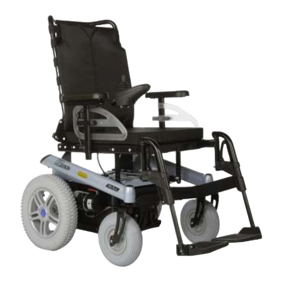
Page 7: Product Description
The wheelchair can be used on solid ground both indoors and outdoors. Fig. 1 Main Components Backrest Brake release Joystick and control panel Footplate Armrest (side panel) Motor with drive wheel Seat cushion Anti-tipper B500 online/e-europe 03/2011 Page 7... - Page 8 ► The power wheelchair may only be operated by a qualified user. ► Have the user or attendant trained in operation of the power wheelchair by authorised personnel instructed by Otto Bock. ► As the user, read the entire Instructions for Use. Fig. 2 Anti-tipper ►...
- Page 9 ► Only use the power wheelchair within a temperature chair are not highly flammable, but there is a possibil range of -25 °C to +50 °C (-13 °F to 122 °F). ity they may catch fire. Utmost caution is therefore required near any open fires. B500 online/e-europe 03/2011 Page 9...
- Page 10 Chapter "Usage" > "Power Seat Functions" ■ Chapter "Usage" > "Manual Seat Functions" ■ Chapter "Usage" > "Disassembly/Transport" ■ Chapter "Usage" > "Use in a Wheelchair Accessible Vehicle" ■ Chapter "Usage" > "Care" ■ Chapter "Maintenance/Repair" ■ Chapter "Disposal" Page 10 03/2011 B500 online/e-europe...
- Page 11 Read the instructions for use before using the product. Observe safety instructions found in the instructions for use Manufacturer information / address Country of origin Electric driving mode: lock motor brake Manual pushing mode: unlock motor brake B500 online/e-europe 03/2011 Page 11...
- Page 12 Safety Label Meaning Risk of pinching. Do not reach into the danger area. Page 12 03/2011 B500 online/e-europe...
- Page 13 ► Remove the fuse if the wheelchair is not used for more than 3 days. 4.2.1 B500 online model The B500 online power wheelchair does not have any of INFORMATION the power seat options described below. To remove the fuse: see Page 69 et. seq.
- Page 14 Maintain an ambient temperature between -40 °C and marks where they come into contact with the ground. +65 °C (-40 °F to 149 °F) and a relative humidity Therefore Otto Bock recommends grey tires if the between 45 and 85 %. wheelchair is primarily used indoors.
- Page 15 ■ Installing the side panels: see Page 22 ► Perform the work with the aid of a helper for support. ■ Installing the footrests: see Page 23 ■ Charging the battery: see Page 38 et. seq. B500 online/e-europe 03/2011 Page 15...
- Page 16 3) Push the lever down until the lock engages (see Fig. 3, item. 2). 4) Check the bolt and lock to ensure that they are securely engaged. Fig. 3 Place the cross bolt into the bracket (top); locked cross bolt (bottom) Cross bolt Lock with lever Page 16 03/2011 B500 online/e-europe...
- Page 17 Locking bolts before adjustments are made. Recaro® Seat 5.3.2 Adjusting the back angle WARNING Standard/contour seat 1) Pull on the strap until the locking bolts are free. Incorrect Recaro® Seat settings Risk of falling, tipping B500 online/e-europe 03/2011 Page 17...
- Page 18 (see Fig. 5, item. 2). Fig. 5 Adjusting the Recaro® Seat angle Release handle Back angle adjustment knob 5.3.3 Adjusting the side panels INFORMATION To remove and install the side panels: see Page 22. Page 18 03/2011 B500 online/e-europe...
- Page 19 Allen head bolt for height adjustment INFORMATION Adjusting the armrest to the forearm length 1) Loosen the 2 Allen head screws on the bottom of the To remove and install the footrests: see Page 23. armrest (see Fig. 7). B500 online/e-europe 03/2011 Page 19...
- Page 20 To adjust the belt lengths: see Page 54. 3) Re-tighten the footrest bar screws. 5.3.6 Adjusting the control panel INFORMATION The power wheelchair can be equipped with an optional swing-away control panel holder (see Page 53). Page 20 03/2011 B500 online/e-europe...
- Page 21 Risk of falling, tipping, collision with persons or objects in the vicinity ► Programming may only be performed by authorised personnel trained by Otto Bock. Otto Bock and the control unit manufacturer are not liable in case of damage caused by programming which was not per...
- Page 22 3) Tighten the thumb screw on the side panel holder INFORMATION If necessary, the hook and loop clos again. ures for routing the control panel cable can be loosened and the control panel can be removed. Page 22 03/2011 B500 online/e-europe...
- Page 23 1) Hook the footrest into the holder from above. 5) Pull the footrest up and remove it. 2) Swing the footrest forward until the footrest lock engages. 3) Hook the calf band into the holder. B500 online/e-europe 03/2011 Page 23...
- Page 24 Page 23). Users can choose the method for getting into and out of the 5) Put the lap belt on when necessary (when driving on wheelchair which is most suitable for them. the road). Page 24 03/2011 B500 online/e-europe...
- Page 25 7) Put the lap belt on when necessary (when driving on the road). 6.4 Control unit CAUTION Uncontrolled driving behaviour due to interference from electromagnetic fields Risk of falling, tipping, collision with persons or nearby objects Fig. 13 Footrest removed B500 online/e-europe 03/2011 Page 25...
- Page 26 Selected speed level (LED Charging / programming tions and components. display) receptacle The following control panel versions are available: Page 26 03/2011 B500 online/e-europe...
-
Page 27: Drive-Away Lock
[Lights On/Off] Button Seat function 1/2 (LED display) 3B Seat function 2 (LED display) [On/Off] Button This LED display shows the currently active power add-on [Decrease Speed] Button Battery capacity (LED dis function. play) [Increase Speed] Button B500 online/e-europe 03/2011 Page 27... - Page 28 The "Battery Capacity" LED display (see Fig. 14, item 7; Battery indicator on the control panel see Fig. 15, item 11) is divided into 10 segments and indic Display Information ates the current battery capacity: Battery is charged Page 28 03/2011 B500 online/e-europe...
- Page 29 Risk of falling out of the power wheelchair Lack of driving experience ► Always wear the safety belt / lap belt when driving in Risk of tipping, falling public. ► Practice on level, open ground first. B500 online/e-europe 03/2011 Page 29...
- Page 30 However, these do not represent a health hazard. The are clearly visible. resulting discomfort can be prevented by customisation measures (attaching a mechanical discharge contact / grounding strap to the power wheelchair frame). The user's environment must be taken into consideration. Page 30 03/2011 B500 online/e-europe...
- Page 31 Risk of accident/falls due to poor traction, reduced brak ■ Uncontrolled driving behaviour may occur on uneven ing effect, or lack of manoeuvrability ground. Therefore the speed must always be adjusted to the ground conditions. B500 online/e-europe 03/2011 Page 31...
- Page 32 - snow-covered or icy areas. Inclines and downgrades: ■ Ascending or descending slopes up to max. 17 % is permitted. Driving on steeper inclines or downgrades is not permitted. Otherwise safe braking is not ensured. Page 32 03/2011 B500 online/e-europe...
- Page 33 ► Only use the power wheelchair if all safety functions, e.g. the automatic brakes, are functional. 6.5.4 Selecting the speed levels ■ The power wheelchair has 5 speed levels. B500 online/e-europe 03/2011 Page 33...
- Page 34 ► Do not cross over any obstacles while driving on inclines or downgrades. INFORMATION ► Reduce speed when driving downhill (e.g. select speed level 1). The control unit of the power wheelchair switches to a safe mode at elevated temperatures and after driving Page 34 03/2011 B500 online/e-europe...
- Page 35 This function is activated/deactivated via play is off and the "Speed Levels" LED indicator is in the control panel. sequential indicator mode. 1) Push the joystick all the way forward until a beep sounds. B500 online/e-europe 03/2011 Page 35...
- Page 36 2) Push the joystick all the way back until a beep sounds. ► Programming may only be performed by authorised personnel trained by Otto Bock. Otto Bock and the 3) Release the joystick. control unit manufacturer are not liable in case of →...
- Page 37 Operation 6.6 Enabling/disabling the brakes ► Repairs and adjustments to the brake may only be made by authorised personnel trained by Otto Bock. WARNING Incorrect settings can lead to a loss of braking power. Uncontrolled rolling It is possible to push the power wheelchair in case of con...
- Page 38 1) Push the brake release lever (see Fig. 17, arrow) up until the brake release bolts engage. tion position may only be performed by authorised personnel trained by Otto Bock. 2) Turn the control unit off and on again. → The driving function is activated.
-
Page 39: General
Never discharge the batteries completely (deep dis ■ Age of the batteries charge). ■ Driving load ■ Charging method Extended driving at the lower end of the battery indicator results in deep discharge which causes battery damage. B500 online/e-europe 03/2011 Page 39... -
Page 40: Battery Charger
► Only use battery chargers from Otto Bock, which Please see the instructions for use supplied with the battery have been verified and approved by Otto Bock for use charger for further details on use and on the LED indicat... -
Page 41: Charging The Battery
► Charge the battery as soon as possible if the last ► Only use battery chargers which have been verified three segments of the "Battery Capacity" LED indicat and approved by Otto Bock for use with the respect or are flashing. ive batteries (observe information on the battery char... -
Page 42: Power Seat Functions
6.8 Power seat functions The power wheelchair can be equipped with a range of optional power seat functions. 6.8.1 Safety Instructions WARNING Exposed pinch points in the seat adjustment and lifting areas Risk of pinching, crushing of limbs Page 42 03/2011 B500 online/e-europe... -
Page 43: Power Seat Tilt
The power seat tilt function allows the seat to be tilted, for example to relief pressure. The seat can be tilted back con NOTICE tinuously up to an angle of 20°. Improper use of power seat options Risk of damage to the product B500 online/e-europe 03/2011 Page 43... -
Page 44: Power Back Angle Adjustment
30°. A seat function is activated by pressing the [Select Additional Power Options] button (see Fig. 15, item 3). This button toggles through "Seat function 1" / "Seat function 2" / "No seat function". Page 44 03/2011 B500 online/e-europe... -
Page 45: Joystick And Display Functions
► Ensure that no body parts, such as hands or feet, are Back: Backrest tilts back in the danger area while manual seat options are ward used. B500 online/e-europe 03/2011 Page 45... -
Page 46: Manual Seat Tilt
3) Let go of the release lever. 2) Move the backrest to the desired position. → The seat is tilted back. 3) Let go of the release lever. The seat is easier to tilt if the backrest is tilted back. Page 46 03/2011 B500 online/e-europe... -
Page 47: Manual Elevating Footrests
Swivelling the footrest the user with improved comfort and lateral support. 1) Activate the release lever on the footrest (see Fig. 23). 2) Move the footrest to the desired position. 3) Let go of the release lever. B500 online/e-europe 03/2011 Page 47... -
Page 48: Recaro® Seat
20° while driving. 2) 2nd person: Pull the headrest up and out. The power wheelchair can be equipped with various Recaro® seat models. They provide individually adjustable, comprehensive seat ing comfort. Page 48 03/2011 B500 online/e-europe... - Page 49 3) To release the rear seat clip from the bracket, tip and Adjusting the Recaro® seat push the seat back a bit. INFORMATION 4) Remove the Recaro® seat. → The Recaro® has been removed. To adjust the back angle of the Recaro® seat: see Page 17. B500 online/e-europe 03/2011 Page 49...
-
Page 50: Headrest
INFORMATION 6.10.3 Headrest This information only applies to the Recaro® LT model. Otto Bock offers the option of equipping the standard and contour seats with a headrest. 1) Turn the knob on the side of the backrest forward. The bracket for attaching the headrest mounting kit is →... -
Page 51: Control Unit Accessories
Primary control active (red Speed level indicator (LED is located on the backrest cross tube. For the Recaro® LED indicator) display) seat, the attendant control is located on the headrest. [Select Additional Power Functions] Button B500 online/e-europe 03/2011 Page 51... -
Page 52: External Odometer
Pressing this button selects seat function 1, then seat func tion 2. The selected seat function is indicated by the LEDs. Pressing the button a third time returns to driving mode (seat function LED display is not lit). Page 52 03/2011 B500 online/e-europe... -
Page 53: Additional Options
Swing-away control panel holder Fig. 29 Swing-away control panel holder with removable control Otto Bock offers the option of equipping the power wheel panel chair with a removable control panel mounted on a swing- away control panel holder. This control panel holder makes 6.12.2 Lights... -
Page 54: Belts / Belt Systems
Lap belt with an audible click. 2) Pull to check that it is secure. CAUTION → The belt is put on. Insufficient support of the seated person Risk of falling out of the power wheelchair Page 54 03/2011 B500 online/e-europe... - Page 55 Buckle > The user sits upright or lies in the power wheelchair. 1) Close the belt. 2) Position the 2 buckle halves in the middle of the body. B500 online/e-europe 03/2011 Page 55...
-
Page 56: Suspension (Steering Casters/Drive Wheels)
6.12.4 Suspension (steering casters/drive wheels) ► Remove objects or clothing which get caught. The power wheelchair may be equipped with a suspension The power wheelchair may be equipped with a four-point system. or chest belt. Page 56 03/2011 B500 online/e-europe... -
Page 57: Locking The Steering Casters
Engaging the steering caster lock ► Push the folding lever on the front of the frame to the side a bit until it disengages from the centre position. B500 online/e-europe 03/2011 Page 57... -
Page 58: Rear Bumper
→ The steering casters are unlocked and can swivel Fig. 35 Steering caster lock, engaged and disengaged freely again. 6.12.6 Rear bumper The power wheelchair may be equipped with a bumper. The bumper provides increased user protection in case of a collision. Page 58 03/2011 B500 online/e-europe... -
Page 59: Overview Of Additional Options
Curb climbing assist: To overcome curbs and steps port the power wheelchair (see the "Technical Data" with a maximum height of 100 mm chapter for the weight of the power wheelchair). ■ Puncture-proof tires: Solid rubber tires B500 online/e-europe 03/2011 Page 59... -
Page 60: Reducing The Transportation Size
2) Remove the side panels. ► For more information please visit the www.iata.org website. Otto Bock recommends contacting the air 3) Fold the backrest forward and onto the seat surface. line directly before every flight to obtain information regarding special transport regulations. - Page 61 3) Pull the release strap back. spring or actuator. 4) Manually fold the backrest forward and onto the seat 3) Remove the cross bolt from the bracket. surface. 4) Fold the backrest forward and onto the seat surface. B500 online/e-europe 03/2011 Page 61...
-
Page 62: Reducing The Transportation Size - Recaro
1) Position the power wheelchair in its transport location. WARNING 2) Turn the control unit off. Use as a seat in a wheelchair accessible vehicle Risk of falling out of the power wheelchair, severe injury in case of accident Page 62 03/2011 B500 online/e-europe... -
Page 63: Permitted Use
The safety components (such as lap belts) sold by Otto Bock only serve to further restrain the person sitting in ► Never transport more than one person in the power the power wheelchair. -
Page 64: Care
► Check the driving behaviour of the power wheelchair after cleaning it. ■ Prior to disinfection, clean the seat and back uphol stery, seat cushion, control panel, and armrest. INFORMATION Piston rods do not require lubrication. They are mainten ance-free. Page 64 03/2011 B500 online/e-europe... -
Page 65: Maintenance / Repair
► The power wheelchair may only be serviced by "Technical Data" chapter. authorised personnel trained by Otto Bock. The func tionality and operating safety of the power wheelchair 7.2 Maintenance must be verified and a service performed at least 1 x per year. -
Page 66: Maintenance Intervals
Check the footplate for damage Manual elevating Check that the ratchet mechanism works properly and is footrest seated securely Check footplates for damage Visual inspection for scratches and oil leaks on the piston Padding/belts Proper condition of the padding Page 66 03/2011 B500 online/e-europe... - Page 67 Lift seat Visual inspection of all moving components, especially cabling - check for damage Check whether the screw connections are tight Caster wheel Clean and lubricate the whole module damper Mounting screws tightened B500 online/e-europe 03/2011 03/2011 Page 67...
- Page 68 Components Activity Before Weekly Monthly every trip Side panel and Armrest and control panel secured armrest Check armrest for damage Gas compression Visual inspection for scratches and oil leaks on the piston spring or actuator Page 68 03/2011 B500 online/e-europe...
-
Page 69: Repair
The control unit is turned off. 1) Lift the seat cushion from the seat plate. 2) Remove the seat plate. 3) Open the clip on the battery tray strap. 4) Remove the battery tray cover. B500 online/e-europe 03/2011 Page 69... - Page 70 1) Remove the fuse from the protective cover. 2) Open the fuse holder cover. 3) Center the fuse on the spring contacts and plug it in. 4) Close the fuse holder cover until you feel it engage. Page 70 03/2011 B500 online/e-europe...
-
Page 71: Replacing A Defective Bulb
7.3.2 Replacing a defective bulb NOTICE Penetration of moisture Risk of damage to the light Fig. 44 Headlights ► During installation, ensure that the plates are seated accurately in the housing. Notch (apply screwdriver here) LED headlight B500 online/e-europe 03/2011 Page 71... - Page 72 4) Pull the bulb out to the front along the left of the spring- tightly. loaded plates. 5) Install the new bulb. 6) Set the plate in place. 7) Install and tighten the 2 Phillips head screws. Fig. 45 Replacing the front direction indicator bulb Page 72 03/2011 B500 online/e-europe...
-
Page 73: Replacing The Battery
If the measures described here do not resolve the faults completely, contact your specialist dealer. The specialist B500 online/e-europe 03/2011 Page 73... -
Page 74: Types Of Notifications
However, the driving function is still available. Fault A fault impairs one or several functions of the power wheel chair. The power wheelchair and its functions are not fully operational until the fault is resolved. Page 74 03/2011 B500 online/e-europe... -
Page 75: Wheelchair Control Unit Fault Overview
Joystick fault Joystick is not in the home Move the joystick to the zero posi position when the unit is tion before turning the unit on turned on Controller fault Defective controller Check all connections B500 online/e-europe 03/2011 Page 75... -
Page 76: Attendant Control Fault Overview
Attendant control joystick not Move the joystick to the zero posi in home position when the tion before turning the unit on unit is turned on Remove attendant control and turn control panel off, then on again Page 76 03/2011 B500 online/e-europe... - Page 77 Maintenance / repair Flashing LED Warning/Fault Cause Possible corrective action Communication error between Defective cable, loose plug Check cabling / plug connections the attendant control (joystick) connection and the control panel/controller B500 online/e-europe 03/2011 03/2011 Page 77...
-
Page 78: Disposal
► Note that the batteries may not be disposed of as attendant should contact the authorised person who fitted household waste. the wheelchair or Otto Bock service (see inside or outside of rear cover for address). 8.2 Disposal Information To dispose of the wheelchair, return it to the specialist 9.2 Liability... -
Page 79: Ce Conformity
IX of the guidelines. The declara Back height 450 or 550 mm (17.7 or 21.7 in) tion of conformity was therefore created by Otto Bock with Back angle 9/1/11/21° or 0/10/20/30° sole responsibility according to appendix VII of the Overall width 645 mm (25.4 in) - Page 80 -25 °C to +50 °C (-13 °F to 122 C21W; 12 V; SV8.5 °F) Rear direction indic C10W; 6 V; SV8.5 ator Transportation and -40 °C to +65 °C (-40 °F to 149 storage temperature °F) Rear light range Page 80 03/2011 B500 online/e-europe...
- Page 81 Appendices Corrosion protection Corrosion protection Coated frame B500 online/e-europe 03/2011 Page 81...
- Page 82 Page 82 03/2011 B500 online/e-europe...
- Page 83 Bogotá / Colombia Fax +91 22 2520 1267 info@ottobock.rs bockuk@ottobock.com Tel. +57 1 8619988 information@indiaottobock.com Otto Bock Polska Sp. z o. o. Otto Bock Ortopedi ve Fax +57 1 8619977 PL–61-029 Poznań Otto Bock France SNC Otto Bock Japan K. K.
- Page 84 Lindenstraße 13 · 07426 Königsee/Germany Hersteller/Manufacturer: Otto Bock Mobility Solutions GmbH Lindenstraße 13 · 07426 Königsee/Germany Phone +49 69 9999 9393 · Fax +49 69 9999 9392 ccc@ottobock.com · www.ottobock.com Otto Bock has a certified Quality Management System in accordance with ISO 13485.
Need help?
Do you have a question about the B500 and is the answer not in the manual?
Questions and answers