Otto Bock B500 Service Instructions Manual
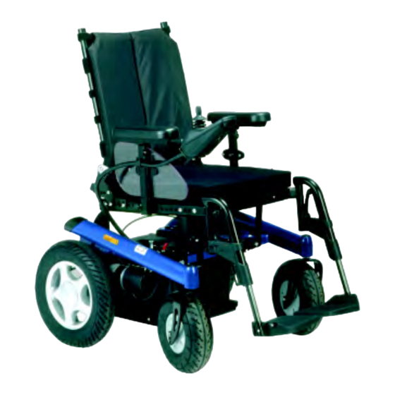
Electric wheelchair
Hide thumbs
Also See for B500:
- Instructions for use manual (156 pages) ,
- User instructions (88 pages) ,
- Using manual (152 pages)
Table of Contents
Advertisement
Advertisement
Table of Contents

Related Manuals for Otto Bock B500


Summary of Contents for Otto Bock B500
- Page 1 Service Instructions Electric wheelchair B500 Q U A L I T Y F O R L I F E...
-
Page 2: Table Of Contents
Table of contents Table of contents 4.1 Foreword....................2 4.2 Safety ...................... 2 4.3 Maintenance schedule and tools needed ..........3 4.4 Settings/substitution/replacement ............6 4.4.1 B500 ......................6 4.4.1.1 Control unit ......................6 4.4.1.2 Battery ........................ 7 4.4.1.3 Frame ......................... 9 4.4.1.4... -
Page 3: Foreword
The operating instructions can be obtained from the manufacturer (see the list of Otto Bock’s branch offices in „Otto Bock Worldwide“). - You can also download the documents from our home page: www.ottobock.de or www.ottobock.com. -
Page 4: Maintenance Schedule And Tools Needed
8 - 24 grip width up to 32 mm Crosstip screwdriver Screwdriver size 2 blade width 2.5; 3.5 and 5.5 mm Plastic hammer Hammer approx. 300 g Diagonal cutter Pin punch Ø 3 mm Page 3 Service Instructions B500... - Page 5 Maintenance schedule and tools needed Drilling machine Liquid “medium strength“ thread lock compound Twist drill Carpet cutter Ø 4 mm with a crescent-shaped Ø 5 mm blade Ø 6 mm Brush and standard grease Page 4 Service Instructions B500...
-
Page 6: Maintenance Schedule
Foot notch socket o Foot board o Foot notch support Control unit accessories o Control unit holder o Joystick o Treatment table Lateral elements o Arm rests o Arm supports Accessories Servicing performed by: dated: Page 5 Service Instructions B500... -
Page 7: Settings/Substitution/Replacement
Recaro seats: - Pull off the head rest - Insert both head rest tubes through the bushings of the escort control (see figure to the left) - Fasten the head rest to the seat. Page 6 Service Instructions B500... -
Page 8: Battery
8 hours, approximately. When charging is complete, first pull out the mains plug, then pull out the charging plug. The B500 is ready to operate after switching the control off and on again. - Page 9 To replace or remove the battery case: - Dismount the seat; for the spring-mounted version, you only need to pull out the drawer - Open the strap as described above - Remove the batteries, and dismount the battery case. Page 8 Service Instructions B500...
-
Page 10: Frame
Use caution to cut the cable binders without damaging any cable using a diagonal cutter or a knife! - Place the B500 on a flat surface, and secure it against rolling away. - Remove the black plastic protector cap... - Page 11 Settings/substitution/replacement Replacing or removing the drive bracket - Turn off the B500, and pull out all plug connections before dismounting the drive bracket - Undo the eight screw connections located at the rear frame (four per side) - Remove frame, seat, and lamps...
- Page 12 - Suspend the spring at the top in the last drive bracket borehole Installing or replacing the tilting protection The B500 tilting protections can only be used in pairs (one left, one right). Use two carriage bolts to secure the tilting protec- tions to the drive bracket (see arrow).
-
Page 13: Motors
Settings/substitution/replacement 4.4.1.4 Motors Replacing or removing the motors - Turn off the B500 before starting any work on the motors - Remove frame and seat (refer to the sections on „Replacing or remov- ing the frame“, and „Replacing or removing the drive bracket“) -
Page 14: Lighting
- Use cable binders to fasten the lighting Seat section cables at both the frame and the seat frame Replacing the fuse The fuse of the B500 is located in a black case inside the battery case. - Open the case and replace the fuse Page 13... - Page 15 Installing and removing the light module The light module is fastened by two screws to the cross strut located under the seat (see arrows). Turn off the B500, and undo all plug-and-socket connections before starting any work on the light module.
-
Page 16: Front Wheels
- Secure the screw connection using „Loctite“, and tighten the screws Replacing or removing the springs To replace the front-wheel fork springs, undo the screw located in the spring. The spring effect is modified by strongly tightening the screw. Page 15 Service Instructions B500... - Page 17 The B600 has a divisible rim. - Loosen the screws, separate the rim, and replace either the inner tube or the outer cover - Replace the tube, or repair it using a com- mercially available bicycle tire repair set Page 16 Service Instructions B500...
- Page 18 Settings/substitution/replacement Installation: - Insert the inner tube into the outer cover - Fit the rim together, and all screws using an Allen key - Inflate the tire Page 17 Service Instructions B500...
-
Page 19: Rear Wheels
- Screw the protection cap to the rim using a crosstip screwdriver Repair instructions on how to replace the outer covers or the inner tubes of pneumatic tires. Refer to the sections 4.4.1.6 on „Front wheels“. Page 18 Service Instructions B500... -
Page 20: Standard Seat
Velcro strips (as required by the user) - Proceed as follows to attach the Velcro strips to the back frame (starting at the top back tube): one narrow, one wide, two narrow, and one wide Velcro strips Page 19 Service Instructions B500... - Page 21 - Mount seat section and lateral element retainers - Position the back part, and secure it using two screws on every side of the back part Please also refer to the section on the standard seat when working on this section. Page 20 Service Instructions B500...
- Page 22 - Press the seat section tightly into place Adjust the seat height To readjust the seat height on the B500, you need to replace the seat lugs. The seat lugs are fas- tened to the front and to the rear of the frame.
- Page 23 The fastening is located to the rear of the cross struts on both sides. - Remove seat cushion and seat section - Undo the two headless setscrews - Remove or readjust the lateral element retainer Page 22 Service Instructions B500...
-
Page 24: Recaro Seat
The Recaro seat support is screwed to the bottom of the seat - Unlock and remove the seat - Lay down the seat, and unscrew the three screws on every side of the seat support using an Allen wrench Page 23 Service Instructions B500... - Page 25 Two retainers are located at the seat surfaces. Perform the following work steps: - Install a locking plate at the front retainer - Hook the back rest to the seating surface - Fasten the front locking device to the rear retainer Page 24 Service Instructions B500...
-
Page 26: Seat Systems Options
Abduction wedges are fastened with a retainer to the front cross strut of the seat frame: - Drill a Ø 6 mm (0.24 in) hole at the centre of the strut - Insert the screw to fasten the retainer Page 25 Service Instructions B500... - Page 27 - Secure the single belt end at this crossbar: - Bend to open the two eyes until they fit over the bar - Insert a screw through the eyes and through the borehole at the centre of the bar, and tighten the screw Page 26 Service Instructions B500...
- Page 28 - Remove the rest of the lining - Use a size 4 drill to enlarge the two boreholes in the sheet metal shield (for the belt fasten- ing screws, see arrows). Page 27 Service Instructions B500...
- Page 29 In a standard seat, the belt is secured and screwed to the end cover using a lug with an eyelet. In a Recaro seat, the hip belt is fastened to the sides such as a safety harness. Page 28 Service Instructions B500...
-
Page 30: Lateral Elements
The arm cushion of the lateral element is fastened to the lateral element rod assembly using two headless setscrews. - Undo the headless setscrews - Replace or move the arm cushions (to improve the setting for the user) Page 29 Service Instructions B500... - Page 31 An arm strap is secured to the arm rest rail. - Insert a metal plate into the rail, and move it to the desired position. - Put both the eyelets of both strap ends on the threaded pin, and secure them using a Page 30 Service Instructions B500...
-
Page 32: Foot Notch
Replacing and installing the foot board Removal: - Undo the screw which connects the foot board and the assembly set Installation: - Tighten the screw which connects the foot board and the assembly set Page 31 Service Instructions B500... - Page 33 - Remove the complete foot notch from the B500 - Undo/tighten the two headless setscrews at the back of the socket using an Allen wrench - Separate the foot support tube from the socket, or adjust it to a new length Page 32 Service Instructions B500...
-
Page 34: Control Unit Accessories
- Secure using the two screws Operating panel Operator panel support Operator panel support Fasten all operator panel supports for the B500 to the arm rest below the arm support: - Unscrew the operator panel - Remove the lateral element from the retainer... -
Page 35: Accessories
Accessories like tetra fork, golf ball, stick, etc. may be put on the metal pin. Stick holder The stick holder of the B500 is fastened to the lateral element at the bottom of the arm cushion. The arm cushion has two boreholes (see arrows) which are used to screw on the stick holder. - Page 36 © 2003 Otto Bock HealthCare GmbH Any reproduction, storage in electronic media, or translation into any foreign language of any or all parts of the present service instructions shall be prohibited unless a written authorization is given by Otto Bock HealthCare GmbH.
Need help?
Do you have a question about the B500 and is the answer not in the manual?
Questions and answers