Otto Bock B600 Instructions For Use Manual
Hide thumbs
Also See for B600:
- Instructions for use manual (178 pages) ,
- Using manual (152 pages) ,
- Instructions for use manual (103 pages)
Table of Contents
Advertisement
Advertisement
Table of Contents

Related Manuals for Otto Bock B600


Summary of Contents for Otto Bock B600
- Page 1 B600 Instructions for Use (User)
- Page 2 Additional options The power wheelchair can be equipped with the following additional options (applicable options are checked): Electronic drive-away lock* [ ] Function enabled [ ] Function disabled If enabled, the function is activated by pressing the mode button on the control panel. The function is deactivated with the joystick.
-
Page 3: Table Of Contents
..............Getting in / transfer .......... Scope of supply ..........Control unit ............ Options ............6.4.1 Control Panel ..........4.2.1 Model B600 ............ 6.4.2 Buttons and display functions ......Storage ............Driving Functions ..........4.3.1 During daily use ..........6.5.1 Safety Instructions ........... - Page 4 Use in a wheelchair accessible vehicle ....6.10 Additional seat options ........6.14.1 Safety Instructions ........... 6.10.1 Contour seat ........... 6.14.2 Permitted use ..........6.10.2 Recaro® seat ........... 6.14.3 Restrictions for Use ......... 6.10.3 Headrest ............6.14.4 Necessary accessories ........4 | Ottobock B600...
- Page 5 ........7.4.2 Wheelchair control unit fault overview ....7.4.3 Attendant control fault overview ......Disposal ............... Safety Instructions ........... Disposal Information ........Legal Information ..........Service life ............Liability ............CE Conformity ..........Warranty terms ..........B600 Ottobock | 5...
- Page 6 Please note also the information in the chapter "Liabil outdoors. ity". Be sure to read these instructions for use before you start using the wheelchair. In particular, please observe the information in the chapters "Safety" and "Use". 6 | Ottobock B600...
-
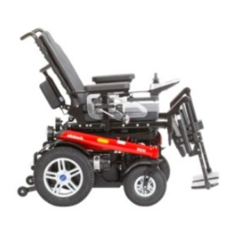
Page 7: Product Overview
3 Control panel 9 Drive wheel 4 Footrest 10 Bumper The wheelchair can be used on solid ground both indoors and outdoors. 5 Charging receptacle 11 Rear LED lights 6 Motor cover 12 Back angle adjustment B600 Ottobock | 7... -
Page 8: General Safety Instructions
► The product may not be used in road traffic by users ► Keep away from any sources of fire, especially burning who have any mental limitations which can temporarily cigarettes. or permanently limit attentiveness and judgement. 8 | Ottobock B600... - Page 9 3.3 Reference to additional safety instructions Observe additional safety instructions in the following chapters: • Chapter "Preparation for Use" • Chapter "Usage" > "Driving Functions" • Chapter "Usage" > "Batteries/Charging Process" • Chapter "Usage" > "Power Seat Functions" B600 Ottobock | 9...
- Page 10 Allowable axle load, front Allowable axle load, rear Maximum gross weight The nameplate is located on the side of the frame below the seat. Manufacturer information/address CE marking – product safety in accordance with EU directives 10 | Ottobock B600...
- Page 11 Safety 3.4.2 Warning labels Label Meaning Electric driving mode: lock motor brake Manual driving mode: unlock motor brake Risk of pinching. Do not reach into the danger area. B600 Ottobock | 11...
- Page 12 NOTICE 4.2.1 Model B600 Deep discharge due to standby current The B600 power wheelchair with telescoping frame can be Risk of battery damage equipped with up to four of the following power seat ► Remove the fuse if the wheelchair is not used for more options: than 3 days.
-
Page 13: Preparation For Use
Black tyres contain soot particles. They may leave black Risk of suffocation marks where they come into contact with the ground. ► Keep packaging materials away from children. Therefore the manufacturer recommends grey tyres if the wheelchair is primarily used indoors. B600 Ottobock | 13... - Page 14 The specialist dealer ships the power wheelchair fully assembled and ready to use. The following additional tasks may be required: • Adjusting settings: see Page 15 et. seq. • Installing the side panels: see Page 20 • Installing the footrests: see Page 21 14 | Ottobock B600...
-
Page 15: Adjustments
2 Lock with lever 1) Pull on the strap until the locking bolts are free. 2) Change the backrest angle to the desired position. 3) Release the strap. The locking bolts engage at the desired position. B600 Ottobock | 15... -
Page 16: Adjusting The Side Panels
20° while driving. 2 Back angle adjustment knob INFORMATION 5.3.3 Adjusting the side panels For further Recaro® seat settings: see the chapter INFORMATION "Recaro® seat". To remove and install the side panels: see Page 20. 16 | Ottobock B600... -
Page 17: Adjusting The Footrests
2) Adjusting the armrest: Adjusting the lower leg length → Version 1:Push the armrest along the slotted holes to the front or back into the desired position ((see CAUTION Fig. 6), left). Exposed pinch points Pinching, crushing of fingers B600 Ottobock | 17... -
Page 18: Adjusting The Belt Lengths
3) Tighten the 3 set screws on the bottom of the armrest. Fig. 7 Adjusting the lower leg length (standard footrest) 5.3.5 Adjusting the belt lengths To adjust the belt lengths: see Page 67. 18 | Ottobock B600... -
Page 19: Adjusting The Telescoping Front Frame
(see Fig. 9). Because this adjustment involves the displacement of the centre of gravity, it may only be carried out by quali fied personnel. B600 Ottobock | 19... -
Page 20: Usage
Fig. 10). 2) Insert the side panel into the side panel holder. 2) Pull the side panel out from the side panel holder and 3) Re-tighten the wing screw on the side panel holder. set it aside. 20 | Ottobock B600... -
Page 21: Footrests
Users can choose the method for getting into and out of the wheelchair which is most suitable for them. Fig. 11 Locking the footrest B600 Ottobock | 21... - Page 22 4) Flip the footrest down or reinstall it and flip it down (see Page 21). 5) Put the lap belt on when necessary (when driving on the road). Fig. 13 Footrest removed (figure taken from 647G385) 22 | Ottobock B600...
-
Page 23: Control Unit
Risk of falling, tipping, collision with persons or nearby objects ► Switch all mobile devices off while driving. ► Turn the control unit off when it is not needed. The power wheelchair is controlled by an enAble50 control unit. B600 Ottobock | 23... -
Page 24: Buttons And Display Functions
7 [Direction Indicator Left/Right] button 6.4.2 Buttons and display functions 4 [Mode] button 8 [Lights On/Off] button INFORMATION If your power wheelchair is equipped with an LCD monitor, please also read the chapter "Separate LCD Monitor" (see Page 54). 24 | Ottobock B600... - Page 25 The horn will sound as long as the button is pressed. [Direction Indicator Left] and [Direction Indicator Right] Button Pressing these buttons activates/deactivates the respective front and rear direction indicators. The direction indicator lights turn off automatically after 20 seconds. B600 Ottobock | 25...
- Page 26 After turning the wheelchair on, the LCD display indicates the battery indicator shows the battery charge level that the selected speed level and battery capacity in the Driving was saved before the wheelchair was last switched off. menu: 26 | Ottobock B600...
-
Page 27: Driving Functions
Battery indicator on the control panel CAUTION Display Information Lack of driving experience Full battery capacity (right: selected Risk of tipping, falling speed level) ► Practise using the product on level, open ground first. Low battery capacity B600 Ottobock | 27... - Page 28 ► Turn all mobile devices off while driving, since the driv CAUTION ing characteristics of the product are affected by elec Risk of uncontrolled driving behaviour tromagnetic fields. Risk of falling, tipping, collision with persons or nearby objects 28 | Ottobock B600...
- Page 29 ► Engage the brake. ► Move your power wheelchair frequently or have a way to jack it up for storage. B600 Ottobock | 29...
-
Page 30: Driving Notes
50 mm may not be crossed. – Snow-covered or icy areas • Always approach obstacles directly from the front (never at an angle with only one caster wheel). • Always reduce speed to cross over obstacles (e.g. select speed level 1). 30 | Ottobock B600... -
Page 31: Switching On And Off
Display Information functions cease. Malfunctions such as an insufficient sup Selected speed level = 1 (left: bat ply of power to the controls are recognised by the soft tery capacity) B600 Ottobock | 31... -
Page 32: Driving
The control unit of the product switches to a safe mode at ► Approach obstacles at right angles and drive over elevated temperatures and after driving uphill for extended them at one go. periods of time, limiting the performance of the product. 32 | Ottobock B600... -
Page 33: Range
"Function disabled" at the factory. The following factors influence the range of a power wheel If this setting needs to be changed, this is done by the chair: authorised person who fitted the wheelchair. • Battery capacity B600 Ottobock | 33... -
Page 34: Drive-Away Lock
→ The control unit turns itself off. 2) The deactivation process is the same as described → The key symbol on the separate LCD monitor indicates under “Deactivation via control panel”. that the drive-away lock is activated: 34 | Ottobock B600... -
Page 35: Steering Lock
Incorrect configuration settings • When the joystick is deflected forward, the power wheelchair drives straight ahead. Falling, tipping over, collision due to programming errors • When the joystick is deflected backward, the power wheelchair always drives straight back. B600 Ottobock | 35... -
Page 36: Enabling/Disabling The Brakes
Uncontrolled rolling ence. Risk of collision with persons nearby objects ► Note the lack of brake functionality when the brake is deactivated. The brake function may only be released in the presence of an attendant. 36 | Ottobock B600... - Page 37 Engaging/activating the brake Brake released 1) Push the brake release lever (see Fig. 18, arrow) up until the brake release bolt engages. 2) Turn the control unit off and on again. → The driving function is activated. B600 Ottobock | 37...
-
Page 38: Batteries/Charging Process
Moreover the battery capacity displayed on the at the factory matches the batteries included in the control panel can differ more significantly from the actual scope of delivery and may not be altered independ battery capacity. ently. 38 | Ottobock B600... -
Page 39: Battery Charger
► Only clean the battery charger with a dry cloth. ging current to be fed into the battery. The battery charger is designed for maintenance-free and low-maintenance batteries. B600 Ottobock | 39... -
Page 40: Charging The Battery
3) Connect the battery charger to the mains socket and mains plug before you disconnect the battery. turn it on. → The charging process starts automatically and the battery capacity is indicated by the LCD screen on the control panel and on the battery charger. 40 | Ottobock B600... -
Page 41: Power Seat Functions
Charging/programming receptacle on the control pan Driving with power seat options Falling, tipping over due to user error ► Drive in street traffic only with the seat tilt and seat height adjustments lowered and with a vertical back rest. B600 Ottobock | 41... - Page 42 ► Note that the maximum permitted load of the power wheelchair may be reduced when using the options NOTICE "Electric seat height adjustment" and "Electric seat tilt" Improper use of power seat options (see section "Technical Data"). Risk of damage to the product 42 | Ottobock B600...
-
Page 43: Power Seat Height Adjustment
(lap belt, four-point belt) and do INFORMATION not lean out beyond the seat surface. ► Please also observe the safety instructions in the sec tion "Power Seat Functions" > "Safety Instructions for Use". B600 Ottobock | 43... -
Page 44: Power Seat Tilt
The driving function remains available even when the seat is ► Use the seat tilt feature only with the backrest in the raised. The speed can be reduced (creep speed) if neces upright position. sary when the seat is raised due to the decreased tipping 44 | Ottobock B600... -
Page 45: Power Back Angle Adjustment
The seat can be tilted back continuously to the angle spe cified above. INFORMATION ► Please also observe the safety instructions in the sec tion "Power Seat Functions" > "Safety Instructions for Use". B600 Ottobock | 45... -
Page 46: Power Footrests
In addition, the electrically adjustable footrests can be INFORMATION removed from their brackets and lifted up (see Fig. 26, item ► Please also observe the safety instructions in the sec tion "Power Seat Functions" > "Safety Instructions for Use". 46 | Ottobock B600... -
Page 47: Controlling Power Seat Functions
The LCD display indicates the currently selected seat function (see following chapter "Joystick and Display Functions"). • To switch between the various seat functions, press the [Mode] button briefly or move the joystick to the right. B600 Ottobock | 47... -
Page 48: Joystick And Display Functions
Back: Seat slowly tips back Forward: Seat slowly tips toward the horizontal posi tion Power back angle Forward: Backrest tilts forward adjustment Back: Backrest tilts backward Power footrest - left Forward: left footrest moves forward Back: Left footrest moves back 48 | Ottobock B600... - Page 49 Forward: Seat functions move forward e.g. coupled power Back: Seat functions move back seat adjustment (back adjustment and seat tilt) * Direction of movement can be modified by the specialist dealer; ** Seat surface and backrest B600 Ottobock | 49...
-
Page 50: Manual Seat Functions
Swivelling the footrest 1) Activate the release lever on the footrest (see Fig. 27). 2) Move the footrest to the desired position. 3) Let go of the release lever. 50 | Ottobock B600... -
Page 51: Recaro® Seat
► Note that the maximum backrest angle is 30° while → The headrest is removed. standing and 20° while driving. The power wheelchair can be equipped with various Recaro® seat models. They provide individually adjustable, comprehensive seating comfort. B600 Ottobock | 51... - Page 52 2) To release the rear seat clip from the bracket, tip and push the seat back slightly. 3) Remove the Recaro® seat. → The Recaro® seat has been removed. Attaching the Recaro® seat to the mobility base CAUTION Recaro® seat not locked in place Risk of tipping 52 | Ottobock B600...
-
Page 53: Headrest
This information only applies to the Recaro® LT model. 1) Turn the knob on the side of the backrest forward. → Both lateral supports are moved closer together. 2) Turn the knob on the side of the backrest backwards. B600 Ottobock | 53... -
Page 54: Control Unit Accessories
LCD display is disabled (see below). The LCD monitor performs the following functions: • The LCD monitor displays the current status of all power functions and electrical components, as well as faults and malfunctions. 54 | Ottobock B600... - Page 55 The battery symbol is shown on the control panel LCD 3 Battery capacity 9 Direction indicator, left display: 4 Drive wheel brake 10 Light Display Information 5 Excess temperature 11 Creep speed Driving information is only shown on 6 Open-end wrench the LCD monitor B600 Ottobock | 55...
- Page 56 Use the joystick to navigate from the Main Menu (see • Driving menu with speed level Fig. 32) to the Options menu and the Favourites Low battery capacity (see Page 84) menu: 56 | Ottobock B600...
- Page 57 • The joystick is used to navigate within all menus and turned on/off submenus: 1) First movement to the right: Pick option 2) First movement to the front: Select option B600 Ottobock | 57...
- Page 58 Return to the initial Driving menu screen Next action: Move the joystick to the right until the desired seat function is selected • Navigation within a selected submenu is also done with the joystick movements described above: 58 | Ottobock B600...
- Page 59 Further information on the LCD monitor is covered in the fol First favourites function selectable lowing chapters: • "Usage" chapter > "Drive-away lock": Drive-away lock • "Usage" chapter > "Power seat functions": see Page 41 • "Maintenance/Repair" chapter > "Troubleshooting": see Page 82 B600 Ottobock | 59...
-
Page 60: Attendant Control
The button is used for switching the power wheelchair on, The module is connected in conjunction with the control activating the drive-away lock and switching the wheelchair panel or as a separate input device. off. 60 | Ottobock B600... - Page 61 Battery over-voltage (e.g. after driv trol panel display (see Page 41 ff.) and by the following ing downhill) LEDs on the attendant control: Continue driving slowly Display Information Red/Orange/Green Charging process/Drive-away lock flashing alternately Power back angle adjustment B600 Ottobock | 61...
-
Page 62: Push-Button Module
Display Information drive in this direction. Power seat height adjustment If the seat functions are accessed with the [Mode] button, then the joystick is used to select and activate the seat func tions (see Page 41 ff.). 62 | Ottobock B600... - Page 63 Power footrests, coupled button and the [Selected function up]/[Selected function down] buttons (see Fig. 36, items 2 and 4). Symbols on the back of the push-button module indicate the corresponding functions. Other special functions (combinations) S1 – S5 B600 Ottobock | 63...
-
Page 64: Special Controls
Push-button module 1 Available power functions 2 [Mode] button 3 Selected function (LED indicator) 4 [Selected function up/down] buttons (see information box) 5 Jack plugs for connecting Piko buttons Fig. 37 Example for a chin special control 64 | Ottobock B600... -
Page 65: Adapter Cable For Piko Button
1) Apply slight pressure to push the control panel holder to odometer. the side. It is connected to the control panel guard. → The pivot element is unlocked. Additional information on using it can be found in the manu facturer's instructions for use. B600 Ottobock | 65... -
Page 66: Lights
1) Loosen the mounting screws. and current can flow (see Fig. 41, right). 2) Adjust the height of the control panel holder. To replace broken lamps: Replacing a defective bulb. 3) Tighten the mounting screw. 66 | Ottobock B600... -
Page 67: Belts / Belt Systems
► Always wear the safety belt / lap belt when driving in public. CAUTION Putting the lap belt on incorrectly Fig. 42 Putting the lap belt on Risk of pressure points, constriction ► Ensure that the buckle lies in the middle of the body. B600 Ottobock | 67... - Page 68 ► When driving in public areas, always wear the four- point or chest belt for additional support. ► Under no circumstances may the belt system be used as part of a restraint system for transportation in a wheelchair accessible vehicle. 68 | Ottobock B600...
-
Page 69: Suspension (Steering Casters/Drive Wheels)
Adjusting the belt length The user sits upright or lies in the power wheelchair. > 1) Close the belt. 2) To lengthen: Turn the length adjustment buckle by 90° Fig. 44 Steering caster suspension and pull. B600 Ottobock | 69... -
Page 70: Locking The Steering Casters
→ The bolt at the bottom edge of the front frame extends The bumper provides increased user protection in case of a and engages with the front fork as soon as the power collision. wheelchair faces straight ahead (see Fig. 46, left). 70 | Ottobock B600... -
Page 71: Overview Of Additional Options
Footrests or armrests may not a maximum height of 100 mm be used as lifting points. • Puncture-proof tyres: Solid rubber tyres • Seating shell adapter: To attach special seating shells; control panel holder for seating shells also available B600 Ottobock | 71... -
Page 72: Reducing The Transportation Size
1) Pull on the backrest release strap. ► The power wheelchair must be secured in accordance 2) Remove the side panels. with the regulations for the transport device. 3) Pull the release strap back. 72 | Ottobock B600... -
Page 73: Reducing The Transportation Size - Recaro® Seat
4) Fold the backrest forward on to the seat surface. to fold the backrest down: see Page 51. 6.13.4 Preparing for transport 1) Position the power wheelchair in its transport location. 2) Turn the control unit off. B600 Ottobock | 73... -
Page 74: Use In A Wheelchair Accessible Vehicle
The securing components (such as lap belts) sold by the manufacturer only serve as additional restraints for the person sitting in the power wheelchair. 74 | Ottobock B600... -
Page 75: Restrictions For Use
► To avoid corrosion, don't use any aggressive cleaning An anchor kit is required to use the power wheelchair as a agents or solvents. seat in a wheelchair accessible vehicle. The qualified per sonnel who fit the wheelchair can provide more information. B600 Ottobock | 75... -
Page 76: Cleaning
Water-based disinfectants should be used. Observe the NOTICE instructions for use provided by the manufacturer. Failure to inspect important product features • Prior to disinfection, clean the seat and back upholstery, Damage to the product seat cushion, control panel and armrests. 76 | Ottobock B600... -
Page 77: Maintenance
For the components, special attention must be paid to the following points in the maintenance table below: • Functionality of the components • Correct adjustment of the components • Damage, deformation • Tightness of screw connections B600 Ottobock | 77... -
Page 78: Maintenance Intervals
Check for damage to footrests Visually inspect the piston rod for scratches and oil leaks Padding/belts Ensure padding is in perfect condition Check the safety belts for wear Check belt buckle for functionality Tyres Check air pressure (see tyre sidewall) 78 | Ottobock B600... - Page 79 Check whether mounting screws are fastened properly rest Check whether screw connections between the armrest and the control unit are tight Check armrest for damage Gas compression Visually inspect the piston rod for scratches and oil leaks spring or actuator B600 Ottobock | 79...
-
Page 80: Repair
2) Pull gently on the battery drawer to roll it out to the rear. Fig. 53 Fuse in the fuse housing 1 Cover open 2 Fuse inserted 3 Fuse holder Fig. 52 Pulling on the release bolt 80 | Ottobock B600... -
Page 81: Replacing A Defective Bulb
3) Turn the defective bulb slightly to unlock it and then remove it. 4) Grasp the new bulb with a cloth, insert it into the socket and lock it in place. 5) Position the cover, hook it on and press it down tightly. B600 Ottobock | 81... -
Page 82: Replacing The Battery
► If any faults, defects or other hazards that can lead to personal injury are detected, the product must be taken out of service immediately. ► Contact your authorised specialist dealer if uncon trolled movement of the product occurs due to a mal function. 82 | Ottobock B600... -
Page 83: Types Of Notifications
The control unit stores a list of all faults which occur. The specialist dealer reads this information, for example during a general overhaul of the power wheelchair. Based on the saved data the specialist dealer determines future service and maintenance intervals. B600 Ottobock | 83... -
Page 84: Wheelchair Control Unit Fault Overview
Move the joystick to the home tion when the unit is position before switching the unit turned on Hand-held control Defective joystick Contact specialist dealer unit fault Controller fault Defective controller Check all connections Contact specialist dealer 84 | Ottobock B600... - Page 85 Back angle adjust Faulty cabling or plug Check cabling/plug connections ment motor fault contacts Contact specialist dealer Defective actuator Seat tilt motor fault Faulty cabling or plug Check cabling/plug connections contacts Contact specialist dealer Defective actuator B600 Ottobock | 85...
- Page 86 Contact specialist dealer Defective drive motor Brake fault Brake disabled Close brake release Defective brake Contact specialist dealer Emergency stop Severe controller/hand- Check cabling/plug connections held control unit and/or Contact specialist dealer drive motor malfunction 86 | Ottobock B600...
-
Page 87: Attendant Control Fault Overview
Defective actuator Contact specialist dealer 2 LEDs below the seat bot Seat height adjustment motor Faulty cabling or plug con Check cabling/plug connec tom are flashing fault tact tions Defective actuator Contact specialist dealer B600 Ottobock | 87... - Page 88 Maintenance/Repair Fault/Warning Cause Possible corrective action Backrest/seat bottom LED is Power seat function temper Overheating due to excessive Cool down phase flashing ature warning load 88 | Ottobock B600...
-
Page 89: Disposal
5 years, provided that it is used of conformity was therefore created by the manufacturer properly and that the service and maintenance instructions with sole responsibility according to appendix VII of the guidelines. B600 Ottobock | 89... -
Page 90: Warranty Terms
Should trademarks in this accompanying document fail to be explicitly identified as such, this does not justify the conclu sion that the denotation in question is free of third-party rights. 90 | Ottobock B600... -
Page 91: Appendices
Armrest height (telescoping armrest) 225 - 350 mm; standard seat, junior: 205 - 275 mm Armrest length (standard) 260 mm Back angle -9/1/11/21° or 0/10/20/30° Overall width 645 mm Overall height 1030 mm Overall length 1080 mm Weight when empty* 107 kg B600 Ottobock | 91... - Page 92 * The specified weights vary according to the selected options and model. ** For further limitations pertaining to maximum load capacity, please refer to the order form. *** = 3-point turn by 180° Electrical system* IP protection rating (according to DIN EN IPX4 60529) Operating voltage 24 V 92 | Ottobock B600...
- Page 93 Climbing ability, basic model*: 9.5° (17%) Approved climbing ability with lowered seat height adjustment feature/seat tilt: max. 6° (10%) Maximum obstacle height 50 mm (100 mm with curb climbing assist) Range (on level surfaces)** approx. 35 km B600 Ottobock | 93...
- Page 94 50%. For information on this, see the section "Range" in the instructions for use (user). *** The braking distance can be correspondingly longer due to user weight, installed options and condition of the tyres, and due to weather and surface conditions. Corrosion protection Corrosion protection Coated frame 94 | Ottobock B600...
- Page 95 Africa Otto Bock HealthCare Otto Bock Algérie E.U.R.L. Otto Bock France SNC Otto Bock Polska Sp. z o. o. Otto Bock de Mexico S.A. de C.V. Otto Bock Korea HealthCare Inc. Deutschland GmbH 91978 Courtaboeuf Cedex 61-029 Poznań · Poland Mackle-Ben Aknoun · Alger C.P.
- Page 96 Ihr Fachhändler | Your specialist dealer Versandanschrift für Rücksendungen/Adress for Returns: Otto Bock Manufacturing Königsee GmbH Lindenstraße 13 · 07426 Königsee-Rottenbach/Germany Otto Bock Mobility Solutions GmbH Lindenstraße 13 · 07426 Königsee-Rottenbach/Germany T +49 (0) 69 9999 9393 · F +49 (0) 69 9999 9392 ccc@ottobock.com ·...
Need help?
Do you have a question about the B600 and is the answer not in the manual?
Questions and answers
Une clé apparaît sur le boîtier et nous n’arrivons pas à faire fonctionner le fauteuil