Table of Contents
Advertisement
Quick Links
Advertisement
Table of Contents
Troubleshooting

Related Manuals for Mitsubishi Electric FX5UC-96MT/D


Summary of Contents for Mitsubishi Electric FX5UC-96MT/D
- Page 1 MELSEC iQ-F FX5UC User's Manual (Hardware)
-
Page 3: Safety Precautions
SAFETY PRECAUTIONS (Read these precautions before use.) Before using this product, please read this manual and the relevant manuals introduced in this manual carefully and pay full attention to safety in order to handle the product correctly. If the equipment is used in a manner not specified by the manufacturer, the protection provided by the equipment may be impaired. - Page 4 *1 Products conforming to the UL explosion-proof standard are as follows: Manufactured in October 2017 onwards FX5 CPU module FX5UC-32MT/D, FX5UC-32MT/DSS, FX5UC-64MT/D, FX5UC-64MT/DSS, FX5UC-96MT/D, FX5UC-96MT/DSS FX5 extension module FX5-C16EX/D, FX5-C16EX/DS, FX5-C16EYT/D, FX5-C16EYT/DSS, FX5-C32EX/D, FX5-C32EX/DS, FX5-C32EYT/D, FX5- C32EYT/DSS, FX5-C32ET/D, FX5-C32ET/DSS, FX5-232ADP, FX5-485ADP, FX5-C1PS-5V, FX5-CNV-BUSC, FX5-4AD-...
- Page 5 [INSTALLATION PRECAUTIONS] WARNING ● Make sure to cut off all phases of the power supply externally before attempting installation or wiring work. Failure to do so may cause electric shock or damage to the product. ● Use the product within the generic environment specifications described in Page 30 Generic Specifications of this manual.
- Page 6 [WIRING PRECAUTIONS] WARNING ● Make sure to cut off all phases of the power supply externally before attempting installation or wiring work. Failure to do so may cause electric shock or damage to the product. ● Make sure to attach the terminal cover, provided as an accessory, before turning on the power or initiating operation after installation or wiring work.
- Page 7 [WIRING PRECAUTIONS] CAUTION ● Perform class D grounding (grounding resistance: 100 or less) of the grounding terminal on the CPU module and extension modules with a wire 2 mm or thicker. Do not use common grounding with heavy electrical systems (refer to Page 95 Grounding). ●...
- Page 8 ● Do not disassemble or modify the PLC. Doing so may cause fire, equipment failures, or malfunctions. For repair, contact your local Mitsubishi Electric representative. ● After the first use of the SD memory card, do not insert/remove the memory card more than 500 times.
- Page 9 [OPERATION PRECAUTIONS] CAUTION ● Construct an interlock circuit in the program so that the whole system always operates on the safe side before executing control (for data change) of the PLC in operation. Read the manual thoroughly and ensure complete safety before executing other controls (for program change, parameter change, forcible output and operation status change) of the PLC in operation.
-
Page 10: Précautions De Sécurité
PRÉCAUTIONS DE SÉCURITÉ (Lire ces précautions avant toute utilisation du produit.) Avant d'utiliser ce produit, lire attentivement ce manuel ainsi que les manuels auxquels il renvoie, et toujours considérer la sécurité comme de la plus haute importance en manipulant le produit correctement. Si vous utilisez mal l'equipement, la protection peut ne pas fonctionner. - Page 11 *1 Les produits sont conformés à la norme pour anti-explosion UL comme suit : Fabriqué à partir d’octobre 2017 Module FX5 CPU FX5UC-32MT/D, FX5UC-32MT/DSS, FX5UC-64MT/D, FX5UC-64MT/DSS, FX5UC-96MT/D, FX5UC-96MT/DSS Module d’extension FX5 FX5-C16EX/D, FX5-C16EX/DS, FX5-C16EYT/D, FX5-C16EYT/DSS, FX5-C32EX/D, FX5-C32EX/DS, FX5-C32EYT/D, FX5-...
- Page 12 [PRÉCAUTIONS DE CONCEPTION] ATTENTION ● À la commande d'une charge inductive comme une lampe, un réchauffeur ou une électrovanne, un fort courant (environ 10 fois supérieur à l'intensité normale) peut traverser la sortie quand celle-ci passe de OFF à ON. Prenez les mesures appropriées pour que l’intensité de courant ne dépasse pas la valeur correspondant à...
- Page 13 [PRÉCAUTIONS D'INSTALLATION] ATTENTION ● Ne pas toucher directement les parties conductrices du produit. Cela pourrait être à l'origine d'une panne ou d'un dysfonctionnement. ● Lors du perçage des trous de vis ou du câblage, assurez-vous que les débris de coupe et de câblage ne pénètrent pas dans les fentes de ventilation du contrôleur programmable.
- Page 14 [PRÉCAUTIONS DE CABLAGE] AVERTISSEMENT ● Assurez-vous de couper toutes les phases de l'alimentation externe avant d’essayer l'installation ou le câblage. Faute de quoi, il y a risque d'électrocution ou d'endommagement du produit. ● Assurez-vous d'attacher le couvercle de borne, fourni en tant qu'accessoire, avant d'alimentation ou d'opération de lancement après installation ou câblage.
- Page 15 [PRÉCAUTIONS DE CABLAGE] ATTENTION ● Effectuer la mise à la terre classe D (résistance à la mise à la terre : 100 ou moins) de la borne de mise à la terre sur le module CPU et les modules d'extension avec un fil de 2 mm ou plus épais.
- Page 16 ● Ne pas démonter ni modifier le contrôleur programmable. Cela pourrait causer un départ de feu, une panne ou un dysfonctionnement des équipements. Pour réparation, contactez votre représentant local de Mitsubishi Electric. ● Après la mise en service de la carte-mémoire SD, ne pas insérer/retirer la carte-mémoire plus de 500 fois.
- Page 17 [PRÉCAUTIONS DE MISE AU REBUT] ATTENTION ● Veuillez contacter une société certifiée de mise au rebut des déchets électroniques pour le recyclage et la mise au rebut écologique de votre équipement. ● Les piles ou batteries doivent être mises au rebut séparément des autres déchets et conformément à la réglementation locale.
-
Page 18: Introduction
• Since the examples indicated by this manual, technical bulletin, catalog, etc. are used as a reference, please use it after confirming the function and safety of the equipment and system. Mitsubishi Electric will accept no responsibility for actual use of the product based on these illustrative examples. - Page 19 MEMO...
-
Page 20: Table Of Contents
CONTENTS SAFETY PRECAUTIONS ..............1 PRÉCAUTIONS DE SÉCURITÉ... - Page 21 CHAPTER 4 SYSTEM CONFIGURATION Rules of System Configuration ............53 Limitations on the Number of Connected Extension Devices .
- Page 22 CHAPTER 6 WIRING Wiring Preparations ..............89 Wiring procedure .
- Page 23 CHAPTER 9 TROUBLESHOOTING Troubleshooting Procedure ............. . 141 Checking with LEDs .
- Page 24 Appendix 9 Handling of Batteries and Devices with Built-in Batteries in EU Member States ....193 Disposal precautions ..............193 Exportation precautions.
-
Page 26: Relevant Manuals
RELEVANT MANUALS Manual name <manual number> Description MELSEC iQ-F FX5UC CPU Module Hardware Manual Describes the details of input/output specifications, wiring and installation of the <JY997D61001> FX5UC CPU module from MELSEC iQ-F FX5UC User's Manual (Hardware). MELSEC iQ-F FX5 User's Manual (Startup) Performance specifications, procedures before operation, and troubleshooting of the <JY997D58201>... -
Page 27: Terms
FX5U-64MT/ESS, FX5U-80MR/ES, FX5U-80MT/ES, FX5U-80MT/ESS, FX5U-32MR/DS, FX5U-32MT/DS, FX5U-32MT/DSS, FX5U-64MR/DS, FX5U-64MT/DS, FX5U-64MT/DSS, FX5U-80MR/DS, FX5U-80MT/DS, and FX5U-80MT/DSS FX5UC CPU module Generic term for FX5UC-32MT/D, FX5UC-32MT/DSS, FX5UC-64MT/D, FX5UC-64MT/DSS, FX5UC-96MT/D, FX5UC-96MT/DSS, FX5UC-32MT/DS-TS, and FX5UC-32MT/DSS-TS Extension module Generic term for FX5 extension modules and FX3 function modules •... - Page 28 Abbreviation of Secure Digital Memory Card. Device that stores data using flash memory. Peripheral device Generic term for engineering tools and GOTs Generic term for Mitsubishi Electric Graphic Operation Terminal GOT1000 and GOT2000 series ■Software packages Engineering tool The product name of the software package for the MELSEC programmable controllers...
-
Page 29: Chapter 1 Outline
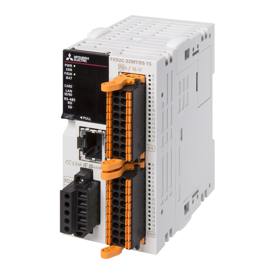
OUTLINE Part Names Front panel Connector type Spring clamp terminal block type When the front covers are open [11] [17] [16] [12] [15] [13] [10] [14] Name Description Expansion adapter connecting When connecting an expansion adapter, secure it with these hooks. hooks Built-in RS-485 communication Terminal block for connection with RS-485-compatible devices... -
Page 30: Side
Name Description DISP switch Switches input/output of the I/O display LED. Output connector Connector for connecting output signal cables. For details on the terminal layout, refer to Page 39 Terminal Layout. [10] DIN rail mounting hook Hook for mounting a CPU module on a DIN rail of DIN46277 (35 mm wide). [11] Input terminal Terminals for input. - Page 31 Bottom side Name Description Battery cover Cover for protecting the battery connecting connector. Power connector for CPU module Connector for connecting power cables. RS-485 terminal resistor selector switch Switch for switching terminal resistance for built-in RS-485 communication. Use a tool such as a screwdriver to operate the RS-485 terminal resistance selector switch. Make sure that the tip of a tool does not damage the switch or case.
-
Page 32: Chapter 2 Specifications
SPECIFICATIONS The CPU module specifications are explained below. Generic Specifications Item Specifications *2*3 Operating ambient temperature -20 to 55, non-freezing Storage ambient temperature -25 to 75, non-freezing Operating ambient humidity 5 to 95%RH, non-condensation Storage ambient humidity 5 to 95%RH, non-condensation *5*6 Vibration resistance ... -
Page 33: Power Supply Specifications
■Expansion adapter For information concerning the dielectric withstand voltage and insulation resistance of each expansion adapter, refer to manuals of each expansion adapter. ■Intelligent function module For information concerning dielectric withstand voltage and insulation resistance of each intelligent function module, refer to manuals of each intelligent function module. -
Page 34: Input Specifications
Input Specifications The CPU module input specifications are explained below. 24 V DC input (sink/source) Input numbers in the table indicate the CPU module umbers. Item Specifications No. of input points FX5UC-32MT/ 16 points FX5UC-64MT/ 32 points FX5UC-96MT/ 48 points Connection type FX5UC-MT/D(SS) Connector... - Page 35 Item Specifications Input signal format FX5UC-MT/D No-voltage contact input (Input sensor form) NPN open collector transistor FX5UC-MT/DS No-voltage contact input Sink: NPN open collector transistor Source: PNP open collector transistor Input circuit insulation Photo-coupler insulation Indication of input operation LED is lit when input is on (DISP switch: IN) Input circuit configuration FX5UC-MT/D Fuse...
-
Page 36: Output Specifications
Output Specifications The CPU module output specifications are explained below. Transistor output Item Output specifications No. of output points FX5UC-32MT/ 16 points FX5UC-64MT/ 32 points FX5UC-96MT/ 48 points Connection type FX5UC-MT/D(SS) Connector FX5UC-32MT/DS(S)-TS Spring clamp terminal block Output type FX5UC-MT/D(S-TS) Transistor/sink output FX5UC-MT/DSS(-TS) Transistor/source output... -
Page 37: Performance Specifications
Performance Specifications Item Specifications Control system Stored-program repetitive operation Input/output control system Refresh system (Direct access input/output allowed by specification of direct access input/output [DX, DY]) Programming Programming language Ladder diagram (LD), structured text (ST), function block diagram/ladder diagram (FBD/LD) specifications Programming extension function Function block (FB), function (FUN), label programming (local/global) - Page 38 Number of device points Item Base Max. number of points No. of user device points Input relay (X) 1024 points The total number of X and Y assigned to input/output points is up to 256 points. Output relay (Y) 1024 points Internal relay (M) 32768 points (can be changed with parameter) Latch relay (L)
-
Page 39: Communication Specifications
Communication Specifications The built-in Ethernet and built-in RS-485 communication specifications are as explained below. Built-in Ethernet communication For details of built-in Ethernet communication, refer to the following. MELSEC iQ-F FX5 User's Manual (Ethernet Communication) MELSEC iQ-F FX5 User's Manual (SLMP) CC-Link IE Field Network Basic Reference Manual Item Specifications... -
Page 40: Built-In Rs-485 Communication
Mass (weight) FX5UC-32MT/D 42.1 mm Approx. 0.2 kg FX5UC-32MT/DSS FX5UC-64MT/D 62.2 mm Approx. 0.3 kg FX5UC-64MT/DSS FX5UC-96MT/D 82.3 mm Approx. 0.35 kg FX5UC-96MT/DSS • Exterior color Main body: Munsell 0.6B7.6/0.2 • Accessories Manual supplied with product FX2NC-100MPCB power cable: 1 m FX2NC-100BPCB power cable: 1 m(FX5UC-MT/D only) -
Page 41: Terminal Layout
Spring clamp terminal block type Unit: mm 93.7 Model Mass (weight) FX5UC-32MT/DS-TS 48.1 mm Approx. 0.25 kg FX5UC-32MT/DSS-TS • Exterior color Main body: Munsell 0.6B7.6/0.2 • Accessories Manual supplied with product FX2NC-100MPCB power cable: 1 m Terminal Layout Built-in RS-485 terminal European-type terminal block RDA (RXD+) RDB (RXD-) - Page 42 Notch Notch COM0 COM0 COM0 COM0 COM1 COM1 FX5UC-96MT/D FX5UC-96MT/DSS Input Input Input Input Input Input Notch Notch COM0 COM0 COM1 COM1 COM2 COM2 ...
- Page 43 Input/output terminal FX5UC-32MT/DS-TS FX5UC-32MT/DSS-TS Input Input Output Output COM0 COM0 Power connector (Red) (Black) 3 Ground (Green) 2 SPECIFICATIONS 2.9 Terminal Layout...
-
Page 44: Chapter 3 Product List
• FX5UC-64MT/D • FX5-C16EX/DS • FX5-C16EYT/DSS • FX5-4DA-ADP Connector • FX5UC-64MT/DSS • FX5-4AD-PT-ADP • FX5-C32EX/D • FX5-C32EYT/D conversion module • FX5UC-96MT/D • FX5-C32EX/DS • FX5-C32EYT/DSS • FX5-4AD-TC-ADP • FX5-CNV-IFC • FX5UC-96MT/DSS • FX5-C32EX/DS-TS • FX5-C32EYT/D-TS Communication • FX5UC-32MT/DS-TS • FX5-C32EYT/DSS-TS Extension power •... -
Page 45: Cpu Module
64 points 32 points 32 points 24 V DC Transistor Connector (sink) (sink) FX5UC-64MT/DSS 24 V DC Transistor (sink/source) (source) FX5UC-96MT/D 96 points 48 points 48 points 24 V DC Transistor Connector (sink) (sink) FX5UC-96MT/DSS 24 V DC Transistor (sink/source) (source) The model name of the CPU module can be checked on the nameplate on the right side. -
Page 46: Extension Module
Extension Module Extension modules are used to expand inputs/outputs, functions, and others. The two connection types, extension connector type and extension cable type, are provided for extension modules. Extension connector type Extension cable type • • Pullout tab Extension connector Extension cable FX5-CNV-IFC or FX5-C1PS-5V is required to use modules of extension cable type. - Page 47 Input module Input modules are used to expand inputs. ■Extension connector type Model Number of input/output points Input type Output Input/ Current consumption type output Total No. No. of No. of 5 V DC 24 V DC External 24 V DC connection of points input...
- Page 48 ■Extension cable type Model Number of input/output points Input type Output Input/ Current consumption type output Total No. No. of No. of 5 V DC power 24 V DC power connection of points input output supply supply type points points FX5-8EYR/ES 8 points ...
-
Page 49: Intelligent Function Module
High-speed pulse input/output module The high-speed pulse input/output module is a product for extending the high-speed input/output. Model No. of input/output points Input type Output Input/ Current consumption type output Total No. No. of No. of 5 V DC power 24 V DC power connection of points... - Page 50 ■Network Model Function No. of occupied Current consumption input/output 5 V DC power 24 V DC External 24 V DC points supply power supply power supply FX5-CCLIEF Intelligent device station for CC-Link IE Field 8 points 10 mA 230 mA network FX5-CCL-MS Master station/intelligent device station for CC-...
-
Page 51: Extension Power Supply Module
■Network Model Function No. of occupied Current consumption input/output 5 V DC power 24 V DC External 24 V DC points supply power supply power supply FX3U-16CCL-M Master station for CC-Link (compatible with Ver. 8 points 240 mA 2.00 and Ver. -
Page 52: Bus Conversion Module
Bus conversion module Bus conversion modules are used to connect FX3 intelligent functions modules in FX5UC systems. For details of the specifications of each bus conversion module, refer to the hardware manual of each product. Model Function No. of occupied Current consumption input/output 5 V DC power supply... -
Page 53: Terminal Module
Terminal Module For details of the terminal modules, refer to Page 178 Terminal Module. Model Function No. of occupied Current consumption input/output 5 V DC power 24 V DC External 24 V DC points supply power supply power supply ... -
Page 54: Chapter 4 System Configuration
SYSTEM CONFIGURATION Configuration of a whole system The configuration of an entire system is shown below as an example. For assignment of the module numbers for extension module, refer to Page 74 Module number of extension modules. Configuration of a whole system Expansion CPU module FX5 extension module... -
Page 55: Rules Of System Configuration
Rules of System Configuration The system configuration must meet the following four requirements. Number of connected extension devices The number of extension devices that can be connected to a single system of FX5UC CPU modules is limited. For details, refer to Page 55 Limitations on the Number of Connected Extension Devices. System configuration example using input/output modules and intelligent modules for connecting. - Page 56 Current consumption The power to the extension devices is supplied from a CPU module, powered input/output module or extension power supply module. The number of extension devices that can be connected must be determined from the power supply capacity of the CPU module or extension power supply module.
-
Page 57: Limitations On The Number Of Connected Extension Devices
Limitations on the Number of Connected Extension Devices Number of connected expansion adapters There is a limitation on the number of expansion adapters connected to the FX5UC CPU module as follows. Type Limitation Communication adapter Up to 2 adapters can be connected Analog adapter Up to 4 adapters can be connected Expansion adapter... - Page 58 Connection to the CPU module There is a limitation on the number of extension modules connected to the FX5UC CPU module as follows. The number of modules connected on the right side of the CPU module must be as follows. Type Limitation Total No.
- Page 59 Connection to the extension power supply module There is a limitation on the number of extension modules connected to the extension power supply module as follows. The number of connected modules from the right side of the extension power supply module to the next extension power supply module added later must be as follows.
-
Page 60: Limitation On The Number Of Input/Output Points
Limitation on the Number of Input/Output Points With the FX5UC CPU modules, a total of 512 points including the number of input/output points of extension devices (max. 256 points) and the number of remote I/O points (max. 384 points) can be controlled. Number of input/output points on whole system Up to 512 points 1. -
Page 61: Calculation Of The Number Of Remote I/O Points
Total number of input/output points of the CPU module and I/O modules Count the total number of input/output points of the CPU module and I/O modules. To obtain the total number of input/output points, count the input points (X0 and more) and output points (Y0 and more) of the CPU module and I/O modules. - Page 62 CC-Link IE field network Basic remote I/O Remote I/O points that are used in CC-Link IE field network Basic are calculated as "number of occupied stations 64 points”. Maximum number of CC-Link IE field Actually used CC-Link IE field network Basic remote I/O points network Basic remote I/O points ...
-
Page 63: Limitation On Current Consumption
Limitation on Current Consumption Power required for expansion adapters and extension modules is supplied from the CPU module, powered input/output module or extension power supply module. The number of extension devices that can be connected must be determined from the capacity of the power supply. Power supply check from the CPU module (current consumption calculation) Check if power can be supplied to extension devices with the power supply capacity of the CPU module. - Page 64 Check if expansion to the CPU module is permitted. • 5 V DC power supply 5 V DC Current consumption Calculation result power supply capacity Total number of CPU module extension devices 0 mA 720 mA 630 mA 90 mA •...
-
Page 65: Power Supply Check From The Powered Input/Output Module (Current Consumption Calculation)
Power supply check from the powered input/output module (current consumption calculation) If 5 V DC and 24 V DC power supplies of the CPU module are insufficient and system cannot be extended, add a powered input/output module. Check if power can be supplied to extension modules with the power supply capacity of the powered input/output module. Powered Connector Expansion... -
Page 66: Power Supply Check From Extension Power Supply Module (Current Consumption Calculation)
Check if expansion to the extension power supply module is permitted. • 5 V DC power supply Capacity of 5 V DC Current consumption Calculation result power supply Total of current Powered input/output consumed by extension module module 0 mA mA ≥... - Page 67 If the ambient temperature exceeds 40, use the extension power supply module at the following current values within the derating range. Derating curve Output current [mA] 5 V DC 1200 24 V DC Ambient temperature [] Check the current consumption of extension devices. (Page 44 Extension Module) Type Model...
-
Page 68: Rules Of System Configuration And Examples Of Reconfiguration
Rules of System Configuration and Examples of Reconfiguration The rules of system configuration are explained below referring to a sample system configuration using expansion adapter, I/ O module, and intelligent function module. System configuration example The following system configuration is under consideration. CC-Link To CC-Link master station... - Page 69 Check on limitations when using extension devices Check the use of the extension devices. ■Use of the module of extension cable type (Page 54 Modules of extension cable type) Limitations Judgement When using the extension cable type module, FX5-CNV-IFC or FX5-C1PS-5V should be connected. ■Use of the bus conversion module (Page 54 Bus conversion module) Limitations...
- Page 70 ■Number of remote I/O points (Page 59 Calculation of the number of remote I/O points) Network No. of remote I/O points AnyWireASLINK 64 points Maximum number of Remote I/O points Remote I/O points ≤ 384 points 64 points ■Total number of I/O points and remote I/O points (Page 58 Limitation on the Number of Input/Output Points) Calculation Max.
-
Page 71: System Reconfiguration Example
Capacity of 5 V DC Current consumption Calculation result power supply Total of current CPU module consumed by extension module 720 mA 1150 mA -430 mA Capacity of 24 V Current consumption Calculation result DC power supply Total of current CPU module consumed by extension module... - Page 72 Check of limitation on the number of modules Check if the example system configuration is within the connectable-module range. ■Number of connected expansion adapters (Page 55 Number of connected expansion adapters) Type No. of modules used Limitations Judgment Expansion adapter (Communication) Up to 2 ■Number of connected extension modules •...
- Page 73 Check on limitations when using extension devices Check on limitations when using the extension devices. ■Use of the module of extension cable type (Page 54 Modules of extension cable type) Limitations Judgement When using the extension cable type module, FX5-CNV-IFC or FX5-C1PS-5V should be connected. ■Use of the bus conversion module (Page 54 Bus conversion module) Limitations...
- Page 74 ■Number of remote I/O points (Page 59 Calculation of the number of remote I/O points) Network No. of remote I/O points AnyWireASLINK 64 points Maximum number of Remote I/O points Remote I/O points ≤ 384 points 64 points ■Total number of I/O points and remote I/O points (Page 58 Limitation on the Number of Input/Output Points) Max.
- Page 75 ■ Check of power supply from the extension power supply module (Page 64 Power supply check from extension power supply module (current consumption calculation)) Power supply capacity of the extension power supply module Type Model Power supply capacity 5 V DC power supply 24 V DC power supply Extension power supply module FX5-C1PS-5V...
-
Page 76: Numbers And Assignment In System
Numbers and Assignment in System Input/output numbers and module numbers in an FX5UC system are explained. Module input/output number The input/output numbers are octal numbers. Input is assigned to "X" and output to "Y." Input/output numbers are used for communication of ON/OFF data between I/O modules and the CPU module. •... -
Page 77: Chapter 5 Installation
INSTALLATION Installation Location Use the PLC under the environmental conditions complying with the generic specifications (Page 30 Generic Specifications). Installation location in enclosure To prevent temperature rise, do not mount the PLC on the floor or ceiling, or in the vertical direction. Always mount the PLC horizontally on the wall as shown in the following figure. -
Page 78: Layout In Enclosure
Configuration in 2 stages with extended extension cable FX5UC CPU module Extended extension cable • FX5-30EC Powered • FX5-65EC input/output module Another equipment ≥50mm Layout in enclosure The PLC components can be laid out in one stage or in two stages, upper and lower. The connecting procedures in each case are explained below. -
Page 79: Examination For Installing Method In Enclosure
Examination for Installing Method in Enclosure Examine the installation location of PLC considering the environmental conditions (Page 30 Generic Specifications). When extension cables are used for the connection, install the products keeping a space of about 2 mm between them. Installing on DIN rail •... -
Page 80: Procedures For Installing On And Detaching From Din Rail
Procedures for Installing on and Detaching from DIN Rail The CPU module can be installed on a DIN46277 rail (35 mm wide). Preparation for installation Connecting extension devices Some extension devices must be mounted on the CPU module before the module is installed in the enclosure. •... -
Page 81: Installation Of Extension Modules (Extension Cable Type)
Installation of extension modules (extension cable type) Push out the DIN rail mounting hook (A in the right figure) of the Back side extension module (extension cable type). Fit the upper edge of the DIN rail mounting groove (B in the right figure) onto the DIN rail. -
Page 82: Procedures For Installing Directly (With M4 Screws)
Procedures for Installing Directly (with M4 Screws) The product can be installed directly in the enclosure (with screws). Position the holes so that there is a gap of about 2 mm between the products. Hole pitches for direct mounting The product mounting hole pitches are shown below. For pitch that varies depending on the product, refer to the table. -
Page 83: Hole Pitches When Extension Module Connected
Hole pitches when extension module connected Unit: mm FX5-CNV-BUS FX5-16EX/ES FX3U-1PG *1 The gap between products is 2 mm. Installation of extension module (extension cable type) Make mounting holes on the mounting surface Rear panel Rear panel according to the external dimensions diagram. Push in the DIN rail mounting hook (A in the right figure) of the extension module (extension cable type). -
Page 84: Connecting Methods For Cpu Module And Extension Devices
Connecting Methods for CPU Module and Extension Devices This section explains the connection methods for extension devices. Connection of extension devices The connection method varies depending on the combination of products, i.e., the CPU module, expansion adapters, and extension modules. The connecting methods are explained with the following configuration example. -
Page 85: Connecting Method B - Connection Of An Extension Module (Extension Connector Type)
Connecting method B - connection of an extension module (extension connector type) This subsection explains how to connect the extension module (extension connector type). Slide the hook for coupling the extension module (A in the right figure) of the existing module (left side). Remove the subsequent extension connector cover (B in the right figure). -
Page 86: Connecting Method C - Connection Of A Connector Conversion Module (Extension Connector Type) Or The Extension Power Supply Module And An Extension Module (Extension Cable Type)
Connecting method C - connection of a connector conversion module (extension connector type) or the extension power supply module and an extension module (extension cable type) This subsection explains how to connect the extension module (extension cable type) to the connector conversion module (extension connector type) or the extension power supply module. -
Page 87: Connecting Method E - Connection Of Extended Extension Cable And Connector Conversion Adapter
Connecting method E - connection of extended extension cable and connector conversion adapter This subsection explains the procedures for connecting an extended extension cable and FX5-CNV-BC to the extension cable of the FX5 extension module. Separate the case of FX5-CNV-BC into two pairs as shown right figure. -
Page 88: Connection Of Power Cables
Connection of power cables Power cable connection of the CPU module, extension power supply module and I/O modules The power must be supplied to the FX5UC CPU module, FX5-C1PS-5V, FX5-CEX/D, and FX5-C32ET/D. Use the power cable for CPU modules to supply the power to the FX5UC CPU module and FX5-C1PS-5V. To supply the power to FX5-CEX/D and FX5-C32ET/D, use two power connectors (upper and lower) on each module for crossover wiring. -
Page 89: Removal Of Power Cables
Removal of power cables Hold part "a" on the connecter of the power cable with your fingers, and remove the cable in the direction of the arrow. Example: FX5UC-32MT/D Push here with fingers. Precautions If the power cable is removed by force, the cable may break. Connection of I/O cables I/O connectors ■Cable connection to I/O connectors... - Page 90 • Terminal module I/O cable Terminal module ■Preparation of I/O connectors • Suitable connector (commercial item) Use 20-pin (1-key) sockets conforming to MIL-C-83503. Check that the sockets do not interfere with peripheral parts including connector covers in advance. • I/O cables (Mitsubishi option) I/O cables on which connectors are attached are prepared.
-
Page 91: Chapter 6 Wiring
WIRING Wiring Preparations Wiring procedure Before wiring, make sure that the source power supply is off. Prepare the parts for wiring. Prepare cables and crimp terminals required for wiring. (Page 90 Cable Connecting Procedure) Connect the power cable. Connect the cable to the power connector. Provide the protection circuit described in this chapter for the power supply circuit. -
Page 92: Cable Connecting Procedure
Cable Connecting Procedure The cable connecting procedure is explained below. European-type terminal block Wire the European-type terminal block in accordance with the following specifications. Suitable wiring No. of wire per terminal Wire size Tightening torque Single wire, Strand wire Ferrule with insulation sleeve Terminal block for built-in One wire 0.3 to 0.5 mm... -
Page 93: Spring Clamp Terminal Block
■Tool For tightening terminals, use a small, commercially-available screwdriver with a straight tip. The recommended shape is shown in the figure on the right. ■Precautions With straight tip When a precision screwdriver with a small grip is used, the specified tightening torque cannot be obtained. Use the following screwdriver or equivalent product (grip diameter: 25 mm) to obtain the tightening torque specified above. - Page 94 Removing and installing the terminal block Follow the below procedures to remove and install the terminal block. ■Lever position to lock and release A 3-step stopper is attached to prevent the lever from rotating, facilitating installation and removal of the terminal block. When removing or installing the terminal block, move the lever to the corresponding position.
-
Page 95: Screw Terminal Block
Connection and disconnection of the cable Spring clamp terminal block is the push-in type, therefore, wiring without a tool is possible by simply inserting the connecting terminal to the terminal block. However, the push-in type does not support stranded wire, and a tool is required for connecting cables. - Page 96 Wire end treatment Crimp terminal size differs depending on terminal screw size and wiring methods used. • Use crimp terminals of the following sizes. ■M3 terminal screw • When a single wire is connected to a single terminal φ3.2 Terminal screw Crimp terminal 6.2 mm or less φ3.2...
-
Page 97: Grounding
Grounding Perform the following. • Perform class D grounding (Grounding resistance: 100 or less). • Ground the PLC independently when possible. • If the PLC cannot be grounded independently, perform the "Shared grounding" shown below. Other Other Other equipment equipment equipment Independent grounding... -
Page 98: Power Supply Wiring
Power Supply Wiring Examples of DC power supply wiring Provide a 24 V DC power supply to FX5UC CPU module and other modules. Use dedicated connectors to provide the power supply. (Refer to Page 86 Connection of power cables.) Power supply wiring example of FX5UC-32MT/D FX5-4DA-ADP 24 V DC Circuit... - Page 99 Power supply wiring example of FX5UC-32MT/DSS 24 V DC Circuit protector FX5-4DA-ADP Power ON FX5UC-32MT/DSS Emergency stop Class D FX5-C32EX/DS grounding Fuse FX5-C32ET/DSS 24 V DC 24 V DC FX5-C1PS-5V Power supply for loads connected to PLC output terminals For details of the emergency stop operation, FX5-C32EYT/DSS refer to "DESIGN PRECAUTIONS".
-
Page 100: Input Wiring
Input Wiring The input wiring of the CPU modules, I/O modules, and terminal modules is explained below. 24 V DC input For input specifications of the CPU modules, refer to Page 32 Input Specifications. For input specifications of the I/O modules, refer to Page 160 Input specifications. For input specifications of the terminal modules, refer to Page 179 Input specifications. - Page 101 Handling of 24 V DC input ■Input terminal • Sink-input-dedicated type When a no-voltage contact or NPN open collector transistor output is connected between an input (X) terminal and the [COM] terminal and the circuit is closed, the input (X) turns on. At this time, the LED corresponding to the DISP switch lights up.
- Page 102 ■Input circuit • Function of an input circuit The primary and secondary circuits for input are insulated with photocoupler, and the second circuit is provided with a C- R filter. The C-R filter is designed to prevent malfunctions caused by chattering of the input contact and noise from input line. Input has a response delay switching from ON to OFF and OFF to ON, shown in the following table.
- Page 103 ■In the case of input device with built-in parallel resistance Use a device with a parallel resistance Rp (k) of the following value or more. Item Specifications Parallel resistance Rp (k) FX5UC-32MT/ X0 to X5 FX5UC-64MT/, X0 to X7 FX5UC-96MT/ High-speed pulse input/output module X0 to X5 FX5UC-32MT/...
- Page 104 ■ In the case of 2-wire proximity switch Use a two-wire proximity switch whose leakage current, I is 1.5 mA or less when the switch is off. If the resistance is larger than leakage current, I of 1.5 mA, connect a bleeder resistance Rb (k), obtained by the following formula as shown in the following figure.
-
Page 105: Input Wiring Example
Input wiring example When a sink-input-dedicated CPU module is used Power FX5UC-32MT/D connector Fuse 24 V DC Class D grounding 3-wire sensor Input Input connector impedance Power connector FX5-C32EX/D Input connector FX5-CNV-IFC 2-wire sensor FX5-16EX/ES Input terminal *1 The grounding resistance should be 100 or less. *2 Handle the power supply circuit properly in accordance with "Power Supply Wiring". - Page 106 When a CPU module common to sink and source inputs is used ■Sink input wiring Power FX5UC-32MT/DSS connector Fuse 24 V DC Class D grounding COM0 3-wire sensor Input connector Input impedance FX5-C32EX/DS COM0 Input connector FX5-CNV-IFC 2-wire sensor FX5-16EX/ES Input terminal *1 The grounding resistance should be 100 ...
- Page 107 ■Source input wiring Power FX5UC-32MT/DSS connector Fuse 24 V DC Class D grounding COM0 3-wire sensor Input connector Input impedance FX5-C32EX/DS COM0 Input connector FX5-CNV-IFC 2-wire sensor FX5-16EX/ES Input terminal *1 The grounding resistance should be 100 or less. *2 Handle the power supply circuit properly in accordance with "Power Supply Wiring".
-
Page 108: Input Wiring Examples Of Terminal Modules
Input wiring examples of terminal modules FX-16E-TB, FX-32E-TB Connectable models: FX5UC-MT/D, FX5-CEX/D, FX5-C32ET/D 0 to 7 (Smaller numbers) 0 to 7 (Larger numbers) Input number of PLC Vacant terminal 3-wire sensor 24 V DC Fuse FX-16E-TB/UL, FX-32E-TB/UL Connectable models: FX5UC-MT/DSS, FX5-CEX/DS, FX5-C32ET/DSS •... - Page 109 • In the case of source wiring 0 to 7 (Larger numbers) 0 to 7 (Smaller numbers) COM0 Input number of PLC Vacant terminal 3-wire sensor PNP 24 V DC Fuse *1 Replace this number with the one of the connected connector. FX-16EX-A1-TB Connectable models: FX5UC-MT/D, FX5-CEX/D, FX5-C32ET/D 0 to 3...
-
Page 110: Output Wiring
Output Wiring The output wiring of the CPU modules, I/O modules, and terminal modules is explained below. Transistor output For output specifications of the CPU modules, refer to Page 34 Output Specifications. For output specifications of the I/O modules, refer to Page 162 Output specifications. For output specifications of the terminal modules, refer to Page 180 Output specifications. - Page 111 For the output module (extension cable type), input/output module (extension cable type), powered input/output module and high-speed pulse input/output module, the transistor output type is a 4-point or 8-point common output type. • Sink output • Source output Connect each COM (number) terminal to the minus side of Connect +V...
- Page 112 ■Output current Maximum load differs for each module. For specifications of each module, refer to the following. For output specifications of the CPU modules, refer to Page 34 Output Specifications. For output specifications of the I/O modules, refer to Page 162 Output specifications. For output specifications of the terminal modules, refer to Page 180 Output specifications.
-
Page 113: Relay Output
Relay output For output specifications of the I/O modules, refer to Page 162 Output specifications. For output specifications of the terminal modules, refer to Page 180 Output specifications. Product life of relay output contacts The product life of relay contacts varies considerably depending on the load type used. Note that loads generating reverse electromotive force or rush current may cause poor contact or welding of contacts which may lead to considerable reduction of the contact product life. - Page 114 Handling of relay output ■Output terminal One common terminal is used for 4 or 8 relay output points. The common terminal blocks can drive loads of different circuit voltage systems (for example: 100 V AC and 24 V DC). Load 24 V DC Fuse COM0...
- Page 115 ■Contact protection circuit for inductive loads An internal protection circuit for the relays is not provided for the relay output circuit in this product. It is recommended to use inductive loads with built-in protection circuits. When using loads without built-in protection circuits, insert an external contact protection circuit, etc.
-
Page 116: Triac Output
Triac output For output specifications of the terminal modules, refer to Page 180 Output specifications. Handling of triac output ■Output terminal Four triac output points are covered by one common terminal. The common terminal blocks can drive loads of different circuit voltage systems (Example: 100 V AC and 24 V DC). - Page 117 Wiring precautions ■Protection circuit for load short-circuiting A short-circuit at a load connected to an output terminal could cause burnout at the output element or the PCB. To prevent this, a protection fuse should be inserted at the output. Load Fuse COM1 Terminal...
-
Page 118: Output Wiring Example
Output wiring example Transistor output ■Sink output type FX5UC-32MT/D COM0 5-30 V DC COM0 Load Fuse Fuse Fuse Inductive load FX5-C32EYT/D COM0 COM0 Load Fuse FX5-CNV-IFC FX5-16EYT/ES COM0 Load Fuse *1 "•" represents a vacant terminal. 6 WIRING 6.6 Output Wiring... - Page 119 ■Source output type FX5UC-32MT/DSS Fuse 5-30 V DC Load Inductive load FX5-C32EYT/DSS Fuse Load FX5-CNV-IFC FX5-16EYT/ESS Fuse Load *1 "•" represents a vacant terminal. 6 WIRING 6.6 Output Wiring...
- Page 120 Relay output FX5UC-32MT/D COM0 24 V DC COM0 Load Fuse FX5-CNV-IFC FX5-8EYR-ES COM0 Load Fuse AC power supply 100 to 240 V COM1 Load Fuse *1 "•" represents a vacant terminal. 6 WIRING 6.6 Output Wiring...
-
Page 121: Output Wiring Examples Of Terminal Modules
Output wiring examples of terminal modules FX-16E-TB, FX-32E-TB Connectable models: FX5UC-MT/D, FX5-CEYT/D, FX5-C32ET/D 0 to 7 (Smaller numbers) 0 to 7 (Larger numbers) COM0 Output number of PLC Vacant terminal Fuse Fuse Fuse 24 V *1 Replace this number with the one of the connected connector. FX-16E-TB/UL, FX-32E-TB/UL Connectable models: FX5UC-MT/DSS, FX5-CEYT/DSS, FX5-C32ET/DSS 0 to 7 (Larger numbers) - Page 122 FX-16EYR-TB, FX-16EYR-ES-TB/UL Connectable models FX-16EYR-TB: FX5UC-MT/D, FX5-CEYT/D, FX5-C32ET/D FX-16EYR-ES-TB/UL: FX5UC-MT/DSS, FX5-CEYT/DSS, FX5-C32ET/DSS 0 to 7 Smaller numbers 0 to 7 Larger numbers PLC output 0 1 2 3 4 5 6 7 0 1 2 3 4 5 6 7 Relay power supply COM1...
- Page 123 FX-16EYT-ES-TB/UL Connectable models: FX5UC-MT/D, FX5-CEYT/D, FX5-C32ET/D PLC output 0 1 2 3 4 5 6 7 0 1 2 3 4 5 6 7 Photocoupler power supply COM1 COM2 COM3 COM4 COM1 COM2 COM3 COM4 Fuse Fuse 24 V For external wiring precautions, refer to Page 110 Wiring precautions. FX-16EYT-ESS-TB/UL Connectable models: FX5UC-MT/DSS, FX5-CEYT/DSS, FX5-C32ET/DSS PLC output...
- Page 124 FX-16EYS-TB Connectable models: FX5UC-MT/D, FX5-CEYT/D, FX5-C32ET/D Surge absorbers are connected to each output. PLC output 0 1 2 3 4 5 6 7 0 1 2 3 4 5 6 7 Photocoupler power supply COM1 COM2 COM3 COM4 COM1 COM2 COM3 COM4 Fuse...
-
Page 125: Examples Of Wiring For Various Uses
Examples of Wiring for Various Uses Notes about examples of wiring The examples of wiring are given under the following conditions. ■Input/output number The input/output numbers are the actual numbers on the program (They may differ from the numbers shown on the product terminals). - Page 126 1-phase 1-input (S/W) The wiring examples in this section use the following settings. When settings other than those in the table are used, use the examples shown in the following figures as references for wiring. CH to be used Pulse input mode External preset input External enable input Operation mode...
- Page 127 2-phase 2-input The wiring examples in this section use the following settings. When settings other than those in the table are used, use the examples shown in the following figures as references for wiring. CH to be used Pulse input mode External preset input External enable input Operation mode...
-
Page 128: Interruption
Interruption Examples of wiring for when the input interruption function is used are shown below. The same wiring is used for the pulse catch and pulse width measurement functions. When capturing pulses of a response frequency of 50 to 200 kHz, refer to Page 102 When a high-speed pulse is captured. -
Page 129: Digital Switch
Digital switch When DSW instructions are used Examples of wiring for capturing values from a 4-digit digital switch to the data register D100 are given below. For the instructions, refer to MELSEC iQ-F FX5 Programming Manual (Instructions, Standard Functions/Function Blocks). ■Example of program SM400 D100... - Page 130 When BIN instructions are used Examples of wiring for capturing values from a 2-digit digital switch to the data register D102 are given below. For the instructions, refer to MELSEC iQ-F FX5 Programming Manual (Instructions, Standard Functions/Function Blocks). ■Example of program SM400 K2X10 D102 ■Example of wiring...
-
Page 131: Input Matrix
Input matrix Examples of wiring to take ON/OFF status of 24 switches by using MTR instructions are given below. For the instructions, refer to MELSEC iQ-F FX5 Programming Manual (Instructions, Standard Functions/Function Blocks). Programming examples SM400 Wiring examples • Sink wiring The example is the wiring for the input/output of the FX5UC-32MT/D. -
Page 132: Seven Segment With Latch
Seven segment with latch For the instructions, refer to MELSEC iQ-F FX5 Programming Manual (Instructions, Standard Functions/Function Blocks). When SEGL instructions are used Examples of wiring for displaying the current value of D100 on the 4-digit 7-segment display are given below. ■Example of program SM400 SEGL... - Page 133 When BCD instructions are used Examples of wiring for displaying the current value of D100 on the 2-digit 7-segment display are given below. ■Example of program SM400 D100 K2Y10 ■Examples of wiring • Sink wiring The example is the wiring for the input/output of the FX5UC-32MT/D. FX5UC-32MT/D Transistor output (sink) COM0...
-
Page 134: Chapter 7 Operation Adjustment
OPERATION ADJUSTMENT Preparation for Operation Preliminary inspection Incorrect connection of the power supply terminal, contact of the DC input wire and power supply wire, or short-circuiting of output wires may result in serious damage. Before applying power, check that the power supply and ground terminals are connected correctly and input/output devices are wired properly. -
Page 135: Connection With A Personal Computer
Reboot the system. Reboot the system by any of the following methods. • Turning off and on the power • Resetting the CPU module (Page 135 Resetting method) Check errors. Check the ERR LED of the CPU module. If an error has occurred, check the contents of the error with Module Diagnostics (CPU Diagnostics) of the engineering tool and eliminate its cause. -
Page 136: Operation And Test
■Serial connection FX5-232ADP COM port (COM1) RS-232 cable (FX-232CAB-1) GX Works3 settings Item Selection item Internal setting Input value PC side I/F Serial/USB RS-232C COM Port COM1 Transmission Speed 115.2Kbps PLC side I/F PLC Module PLC Mode FX5CPU Other Station Setting No Specification Check at Communication Time 30 seconds... -
Page 137: Running, Stopping, And Resetting
Running, Stopping, and Resetting Methods of running, stopping, and resetting The following two methods of running, stopping, and resetting the FX5UC CPU modules are provided. Using the RUN/STOP/RESET switch The operation status of the CPU module can be changed with the RUN/STOP/RESET switch. Setting the RUN/STOP/RESET switch to the RUN position runs the program. -
Page 138: Chapter 8 Maintenance And Inspection
MAINTENANCE AND INSPECTION Daily Inspection Perform the following inspections on a daily basis. Item Inspection item Description Installation status Mounting status of the The module should be securely mounted. of the module module Looseness of cover The cover should not be off. Connection Looseness of terminal Retighten the terminal screws. -
Page 139: Battery
Battery Part names The Latch device memory and clock data upon power interruption. The battery is not incorporated in the CPU module during shipment from the factory. Order it if necessary. Parameter setting is required to back up the device memory and clock data. (Page 138 Setting an optional battery using the engineering tool) External appearance Name... -
Page 140: Battery Replacement
Setting an optional battery using the engineering tool The following setting is required when the capacity of the latch device/latch label is increased using the optional battery. Note that the battery does not back up the data if the following setting is not provided. Select the Navigation window[Parameter][FX5UCPU][CPU Parameter][Memory/Device Setting][Device/Label Memory Area Setting][Option Battery Setting][Mounted] Battery replacement... - Page 141 Replacement procedure If the battery voltage is reduced, replace it following the procedure below. Even with the battery removed, the built-in capacitor holds the data of the memory for the power interruption time (20 sec.). Battery replacement steps 3 and 4 must be completed within 20 seconds. If the time taken for battery replacement is longer than the power interruption time, the data of the memory may be lost.
-
Page 142: Special Relay For Low Battery Voltage
Special relay for low battery voltage Prepare a system which allows constant external monitoring of the battery status, using a GOT, etc. • SM52 (SM8005) The special relay turns ON when the battery voltage is less than the specified value. The special relay turns OFF when the battery voltage returns is normal. -
Page 143: Chapter 9 Troubleshooting
If the PWR LED still does not turn on even after the items shown above are checked, there may be a hardware issue. Consult your local Mitsubishi Electric representative. Checking the BAT LED If the BAT LED is flashing, check the following items. -
Page 144: Checking The Err Led
• Fit a noise filter onto the power supply line. If the ERR LED still does not turn off even after the items shown above are checked, there may be a hardware issue. Consult your local Mitsubishi Electric representative. Checking the P.RUN LED If the P.RUN LED is turned off, check the status of the ERR LED and take corrective actions. -
Page 145: Troubleshooting Using The Engineering Tool
Troubleshooting using the engineering tool Check the error or history using the engineering tool, and identify the error cause. More detailed information on the error as well as the error cause and action to be taken can be checked by using the engineering tool. The engineering tool has the following functions for troubleshooting. -
Page 146: Event History
Event history This function displays the event information, such as errors that occurred in the CPU module, expansion board, expansion adapter and network errors. Since information collected before the CPU module is powered off or reset can also be displayed, the error cause can be identified based on the errors. -
Page 147: Error Status And Operations On Occurrence Of An Error
Stop The module is unable to continue its operation due to a Perform troubleshooting. If the error still persists, consult your hardware issue. local Mitsubishi Electric representative. Moderate Stop The module is unable to carry out programs or continue the... -
Page 148: Backing Up The Data
Backing Up the Data Saving the following information immediately after the occurrence of an error helps analyzing the cause of the error. • Parameters, programs, and device memory • Error histories Backing up parameters, programs, and device memory The procedure for backing up parameters, programs, and device memory by using an engineering tool is explained below. [Online] ... -
Page 149: Troubleshooting For Each Symptom
The output may be turned on unintentionally in the program. Review user program (Duplicate coils or RST instructions). ■When the output does not turn off There may be a hardware issue. Consult your local Mitsubishi Electric representative. Input does not turn on... -
Page 150: Plc Write, Plc Read
The boot operation may be being performed. Read the parameters and review the boot file settings with the engineering tool. If the boot operation is not being performed, there may be a hardware issue. Consult your local Mitsubishi Electric representative. -
Page 151: Appendix
APPENDIX Appendix 1 How to Check the Date of Manufacture Check the date of manufacture of the product as follows. • Nameplate • Module front surface (CPU module only) Checking the nameplate The date of manufacture of the product can be checked from the manufacturer's serial number "S/N" indicated on the nameplate of the product.. -
Page 152: Appendix 2 Standards
EC directive. Compliance to EMC directive and LVD directive of the entire mechanical module should be checked by the user/ manufacturer. For more details please contact to the local Mitsubishi Electric sales site. Requirement for compliance with EMC directive... - Page 153 Requirement for Compliance with LVD directive The following products have shown compliance through direct testing (of the identified standards below) and design analysis (through the creation of a technical construction file) to the European Directive for Low Voltage (2014/35/EU) when used as directed by the appropriate documentation.
- Page 154 Mitsubishi Electric recommends that shielded cables be used. If no other EMC protection is provided, users may experience temporary loss of accuracy between +10%/-10% in very heavy industrial areas.
- Page 155 • Control cabinet - The control cabinet must be conductive. - Ground the control cabinet with the thickest possible grounding cable. - To ensure that there is electric contact between the control cabinet and its door, connect the cabinet and its doors with thick wires.
-
Page 156: Appendix 3 Precautions For Operating Ambient Temperature
Appendix 3 Precautions for Operating Ambient Temperature This section describes precautions when the device is used at an operating ambient temperature below 0. Precaution when used at an operating ambient temperature below 0 • With some exceptions, the operating ambient temperature is -20 to 55 for the FX5 PLCs manufactured in June 2016 onwards. -
Page 157: Appendix 4 I/O Module
Appendix 4 I/O Module Product configuration There are various types of I/O modules. They differ in supply voltage, number of input/output points, input form, output form, and input/output connection type. I/O module Number of Input/output Power supply Input type Output type input/output points connection type PLC internal... - Page 158 Output module : Sink, : Source Sink Source ■Extension connector type Model Input Output Input/output connection Type No. of Common wiring Type No. of Common wiring type points system points system ■Output extension/sink output only Sink FX5-C16EYT/D Transistor Connector ...
- Page 159 ■Extension cable type Model Input Output Input/output connection Type No. of Common wiring Type No. of Common wiring type points system points system ■Input/output extension/sink and source input/relay output only FX5-16ER/ES 24 V DC Sink Source Relay Screw terminal block ■Input/output extension/sink and source input/sink output only FX5-16ET/ES...
-
Page 160: Specifications
Specifications The general specifications are the same as those for the CPU module. (Page 30 Generic Specifications) Power Supply Specifications ■Input module Item Specifications Voltage rating 24 V DC (supplied from external power supply) 5 V DC (supplied from PLC) Current consumption (5 V DC) FX5-C16EX/... - Page 161 ■Powered input/output module Item Specifications Voltage rating 24 V DC Voltage fluctuation range +20%, -30% Allowable instantaneous power failure time Operation can be continued upon occurrence of instantaneous power failure for 5 ms or less. Power fuse 250 V, 3.15 A time-lag fuse Rush current 50 A max.
- Page 162 Input specifications There is the simultaneous ON ratio of available PLC inputs or outputs with respect to the ambient temperature. For details, refer to Page 34 Input/Output Derating Curve. Item Specifications No. of input points FX5-C16EX/ 16 points FX5-C32EX/ 32 points FX5-C32ET/...
- Page 163 Item Specifications Input circuit configuration FX5-CEX/D, 24 V DC FX5-C32ET/D Photocoupler FX5-CEX/DS, Sink input wiring Source input wiring 24 V DC FX5-C32ET/DSS 24 V DC Photocoupler Photocoupler FX5-C32EX/DS-TS, Sink input wiring Source input wiring 24 V DC 24 V DC FX5-C32ET/DS(S)-TS, Photocoupler Photocoupler...
- Page 164 Output specifications There is the simultaneous ON ratio of available PLC inputs or outputs with respect to the ambient temperature. For details, refer to Page 34 Input/Output Derating Curve. ■Transistor output (sink output) Item Specifications No. of output points FX5-C16EYT/D 16 points FX5-C32EYT/D(-TS) 32 points...
- Page 165 Item Specifications Output circuit configuration FX5-CEYT/D(-TS), Load FX5-C32ET/D(S-TS) DC power supply COM0 Fuse COM0 DC power supply COM1 Fuse COM1 FX5-EYT/ES, Load FX5-16ET/ES, FX5-32ET/DS, DC power supply FX5-16ET/ES-H COM0 Fuse DC power supply COM1 Fuse ■Transistor output (source output) Item Specifications No.
- Page 166 Item Specifications Response time OFFON FX5-CEYT/DSS(-TS), 0.2 ms or less/100 mA (at 24 V DC) FX5-C32ET/DSS(-TS) FX5-EYT/ESS, 0.2 ms or less/200 mA (at 24 V DC) FX5-16ET/ESS, FX5-32ET/DSS Y0, Y1, Y4, Y5: 2.5 s or less/10 mA (at 5-24 V DC) FX5-16ET/ESS-H Y2, Y3, Y6, Y7: 0.2 ms or less/200 mA (at 24 V DC) ONOFF...
- Page 167 ■Relay output Item Specifications No. of output points FX5-8EYR/ES 8 points FX5-16EYR/ES 16 points FX5-16ER/ES 8 points FX5-32ER/DS 16 points Connection type Screw terminal block (M3 screws) Output type Relay External power supply 30 V DC or less 240 V AC or less (250 V AC or less when the module does not comply with CE, UL, or cUL standards) Output circuit insulation Mechanical insulation...
-
Page 168: External Dimensions And Component Names
External dimensions and component names Input module, Output module ■Extension connector type • Connector type Unit: mm External dimensions Model W: mm FX5-C16EX/D, FX5-C16EX/DS 14.6 FX5-C16EYT/D, FX5-C16EYT/DSS FX5-C32EX/D, FX5-C32EX/DS 20.1 FX5-C32EYT/D, FX5-C32EYT/DSS Part names Name Description Extension connector Connector connected to extend modules PWR LED Indicates whether the input modules/output modules is powered or not. - Page 169 Part names Name Description Extension connector Connector connected to extend modules PWR LED Indicates whether the input modules/output modules is powered or not. Lit: Powered Off: Not powered or hardware error I/O display LED Lit when input or output is on. I/O terminal Terminals for input, or output.
- Page 170 Input/output module ■Extension connector type • Connector type Unit: mm External dimensions Model W: mm FX5-C32ET/D, FX5-C32ET/DSS 20.1 Part names Name Description Extension connector Connector connected to extend modules PWR LED Indicates whether the input/output modules are powered or not. Lit: Powered Off: Not powered or hardware error I/O display LED...
- Page 171 Name Description Input display LED Lit when input is on. Input terminal Terminals for input. For details on the terminal layout, refer to Page 172 Terminal layout. Output terminal Terminals for output. For details on the terminal layout, refer to Page 172 Terminal layout. Output display LED Lit when output is on.
- Page 172 Powered input/output module 2-4.5 mounting holes [5] [6] Unit: mm 140 (mounting hole pitch) (mounting hole pitch) [Without cover] [10] External dimensions Model W: mm FX5-32ER/DS, FX5-32ET/DS, FX5-32ET/DSS Part names Name Description Extension connector cover (for preceding module) Cover for protecting the extension connector cover (for preceding module). Terminal block cover Cover for protecting the terminal block.
- Page 173 High-speed pulse input/output module Unit: mm Without cover 2-4.5 mounting holes External dimensions Model W: mm FX5-16ET/ES-H, FX5-16ET/ESS-H Part names Name Description Input display LED, Output display Lit when input or output is on. POWER LED Indicates whether the input modules/output modules is powered or not. Lit: Powered Off: Not powered or hardware error Pullout tab...
-
Page 174: Terminal Layout
Terminal layout Extension connector type FX5-C16EX/D FX5-C32EX/D FX5-C32EX/DS-TS FX5-C16EYT/D Input Input Output Input Notch Smaller Notch Notch numbers COM0 COM0 Input Input Larger numbers FX5-C16EX/DS FX5-C32EX/DS FX5-C16EYT/DSS Input Output Input Notch Smaller Notch Notch numbers... - Page 175 FX5-C32EYT/D FX5-C32EYT/D-TS FX5-C32ET/D FX5-C32ET/DS-TS Output Output Input Input Smaller Notch Notch numbers COM0 COM0 COM0 COM0 Output Output Output Output Larger numbers COM1 COM1 COM0 COM0 COM1 COM1 COM0 COM0 FX5-C32EYT/DSS FX5-C32EYT/DSS-TS FX5-C32ET/DSS FX5-C32ET/DSS-TS Output...
- Page 176 Extension cable type FX5-8EX/ES FX5-8EYR/ES FX5-8EYT/ESS FX5-16ER/ES FX5-8EYT/ES FX5-16ET/ES FX5-16ET/ES-H FX5-16EX/ES FX5-16EYR/ES FX5-16EYT/ESS FX5-16ET/ESS FX5-16EYT/ES FX5-16ET/ESS-H Smaller Smaller Smaller numbers numbers numbers Larger Larger Larger numbers numbers numbers FX5-32E/D FX5-32ER/DS, FX5-32ET/DS COM0 COM1 COM2 COM3 FX5-32ET/DSS APPX Appendix 4 I/O Module...
-
Page 177: Appendix 5 Connector Conversion Module
Appendix 5 Connector Conversion Module Connector conversion modules are used to connect FX5 extension modules (extension cable type) in FX5UC systems. External dimensions and component names Unit: mm External dimensions Model W: mm FX5-CNV-IFC 14.6 Part names Name Description Extension connector (for preceding The extension connector that connects to the preceding module (the CPU module side). -
Page 178: Appendix 6 Sd Memory Card
Appendix 6 SD Memory Card An SD memory card is installed in the CPU module to perform the following operation. • Operate using the project data in the SD memory card. • Storing data that is collected by the data logging function to the SD memory card. Part names This section describes the part names of the SD memory card. -
Page 179: Insertion And Removal Of The Sd Memory Card
Formatting To use any SD memory card in the CPU module, the card must be formatted. In the initial state after purchase, the SD memory card is not formatted. Insert the SD memory card to a CPU module and format the SD memory card using the engineering tool before use. -
Page 180: Appendix 7 Terminal Module
Appendix 7 Terminal Module Product configuration Terminal modules are used to convert connector-type I/O terminals into terminal blocks. By using terminal blocks (built-in element Option cable or type) dedicated to input or output, capturing of AC input signals user-created cable and format conversion into the relay/transistor/triac output can be performed. -
Page 181: Specifications
Specifications Exterior color, accessories Item Specifications Exterior color Munsell 0.08GY/7.64/0.81 Accessories Input/output number label, terminal block layout card Input specifications ■FX-16EX-A1-TB Item Specifications Input type AC input Input signal voltage 100 to 120 V AC +10% -15% 50/60 Hz Input signal current 4.7 mA/100 V AC 50 Hz 6.2 mA/110 V AC 60 Hz Input impedance... - Page 182 Output specifications ■Relay output (FX-16EYR-TB, FX-16EYR-ES-TB/UL) Item Specifications Output type Relay External voltage 250 V AC or less, 30 V DC or less Max. load Resistance load 2 A/point The total load current per common terminals (four points) should be 8 A or less. Inductive load 80 VA Min.
- Page 183 ■Transistor/sink output (FX-16EYT-TB, FX-16EYT-ES-TB/UL) Item Specifications Output type Transistor/sink output External voltage 5-30 V DC Max. load Resistance load 0.5 A/point The total load current per common terminals (four points) should be 0.8 A or less. Inductive load 12 W/24 V DC ...
- Page 184 ■Transistor/source output (FX-16EYT-ESS-TB/UL) Item Specifications Output type Transistor/source output External voltage 5-30 V DC Max. load Resistance load 0.5 A/point The total load current per common terminals (four points) should be 0.8 A or less. Inductive load 12 W/24 V DC ...
- Page 185 ■Triac output (FX-16EYS-TB, FX-16EYS-ES-TB/UL) Item Specifications Output type Triac (SSR) External voltage 85 to 242 V AC Max. load Resistance load 0.3 A/point The total load current per common terminals (four points) should be 0.8 A or less. Inductive load 15 VA/100 V AC 36 VA/200 V AC Min.
-
Page 186: External Dimensions And Component Names
External dimensions and component names • FX-16E-TB, FX-16E-TB/UL • FX-32E-TB, FX-32E-TB/UL • FX-16EX-A1-TB • FX-16EYR-TB, FX-16EYR-ES-TB/UL, FX-16EYT-TB, FX-16EYT-ES-TB/UL, FX-16EYT-ESS-TB/UL, FX-16EYS-TB, FX-16EYS-ES-TB/UL Unit: mm (inches) Name Description CN1 connector Connector for connecting input signal cables or output signal cables for CN1 CN2 connector Connector for connecting input signal cables or output signal cables for CN2 (FX-32E-TB and FX-32E-TB/UL only) -
Page 187: Terminal Layout
Terminal layout • FX-16E-TB, FX-16E-TB/UL Smaller numbers Larger numbers • FX-32E-TB, FX-32E-TB/UL Smaller numbers Larger numbers CN1 CN2 Smaller numbers Larger numbers • FX-16EX-A1-TB POWER Smaller numbers Larger numbers COM1 COM2 COM3 COM4 COM1 COM2 COM3 COM4 • FX-16EYR-TB, FX-16EYR-ES-TB/UL, FX-16EYT-TB, FX-16EYT-ES-TB/UL, FX-16EYT-ESS-TB/UL, FX-16EYS-TB, FX-16EYS-ES-TB/UL Smaller numbers Larger numbers COM1... -
Page 188: Internal Circuit
Internal circuit FX-16E-TB, FX-32E-TB 0 to 7 (Smaller numbers) 0 to 7 (Larger numbers) (20) (10) (19) (18) (17) (16) (15) (14) (13) (12) (11) (20) (10) (19) (18) (17) (16) (15) (14) (13) (12) (11) 0 to 7 (Smaller numbers) 0 to 7 (Larger numbers) *1 Replace this number with the one of the connected connector. - Page 189 FX-16E-TB/UL, FX-32E-TB/UL 0 to 7 (Smaller numbers) 0 to 7 (Larger numbers) (20) (10) COM0 (19) COM0 (18) (17) (16) (15) (14) (13) (12) (11) (20) (10) COM0 (19) COM0 (18) (17) (16) (15) (14) (13) (12) (11) 0 to 7 (Smaller numbers) 0 to 7 (Larger numbers) *1 Replace this number with the one of the connected connector.
- Page 190 FX-16EX-A1-TB (20) (10) (19) (18) Photocoupler Photocoupler (17) (16) (15) (14) (13) (12) (11) Photocoupler Photocoupler 0 to 3 4 to 7 0 to 4 to COM1 COM2 COM3 COM4 COM1 COM2 COM3 COM4 0 to 7 Larger numbers 0 to 7 Smaller numbers FX-16EYR-TB...
- Page 191 FX-16EYR-ES-TB/UL (20) (10) (19) (18) (17) (16) (15) (14) (13) (12) (11) 0 1 2 3 4 5 6 7 0 1 2 4 5 6 7 COM1 COM2 COM3 COM4 COM1 COM2 COM3 COM4 0 to 7 Smaller numbers 0 to 7 Larger numbers *1 Replace this number with the one of the connected connector.
- Page 192 FX-16EYT-ES-TB/UL (20) (10) Photo- (19) coupler k k (18) Photo- (17) coupler (16) (15) (14) (13) Photo- (12) coupler k k (11) Photo- coupler 0 to 7 Smaller numbers 0 to 7 Larger numbers 0 1 2 3 4 5 6 7 0 1 2 3 4 5 6 7...
- Page 193 FX-16EYS-TB (20) (10) COM0 (19) COM0 k k (18) Photo- (17) Photo- thyristor (16) thyristor (15) (14) (13) (12) k k (11) Photo- Photo- thyristor thyristor 0 to 7 Smaller numbers 0 to 7 Larger numbers Surge absorbers are connected to each output. 0 1 2 3 4 5 6 7 0 1 2 3...
-
Page 194: Appendix 8 Precautions For Battery Transportation
Appendix 8 Precautions for Battery Transportation When transporting lithium batteries, follow required transportation regulations. Batteries used in the FX5UC CPU modules are classified as follows. Control-subject product Built-in None (FX5UC CPU modules do not include batteries when shipped from the factory.) Battery only (spare parts and optional parts) Model Battery type... -
Page 195: Appendix 9 Handling Of Batteries And Devices With Built-In Batteries In Eu Member States
Appendix 9 Handling of Batteries and Devices with Built-in Batteries in EU Member States This section describes the precautions for disposing of waste batteries in EU member states and exporting batteries and/or devices with built-in batteries to EU member states. Disposal precautions In EU member states, there is a separate collection system for waste batteries. -
Page 196: Appendix 10Added And Changed Functions
Appendix 10 Added and Changed Functions The functions added or changed with the CPU module and engineering tool, and the supported CPU modules' firmware version and engineering tool software version are given below. • The firmware version can be confirmed with module diagnostics (CPU diagnostics). Refer to Page 143 Module diagnostics (CPU diagnostics) for details on the module diagnostics (CPU diagnostics). -
Page 197: Index
INDEX ......27 .......27 BAT LED RD LED . -
Page 198: Revisions
SAFETY PRECAUTIONS, Section 2.1, 2.3, 2.4, 5.1, 6.2, 6.6, Appendix 2, 4, 7 This manual confers no industrial property rights or any rights of any other kind, nor does it confer any patent licenses. Mitsubishi Electric Corporation cannot be held responsible for any problems involving industrial property rights which may occur as a result of using the contents noted in this manual. -
Page 199: Warranty
WARRANTY Please confirm the following product warranty details before using this product. Gratis Warranty Term and Gratis Warranty 2. Onerous repair term after discontinuation of production Range If any faults or defects (hereinafter "Failure") found to Mitsubishi shall accept onerous product repairs for be the responsibility of Mitsubishi occurs during use of seven (7) years after production of the product is the product within the gratis warranty term, the... -
Page 200: Trademarks
TRADEMARKS Microsoft and Windows are either registered trademarks or trademarks of Microsoft Corporation in the United States and/or other countries. Ethernet is a trademark of Xerox Corporation. Anywire and ANYWIREASLINK is a trademark of Anywire Corporation. MODBUS is a registered trademark of Schneider Electric SA. - Page 202 Manual number: JY997D61401J Model: FX5UC-U-HW-E Model code: 09R558 When exported from Japan, this manual does not require application to the Ministry of Economy, Trade and Industry for service transaction permission. HEAD OFFICE: TOKYO BUILDING, 2-7-3 MARUNOUCHI, CHIYODA-KU, TOKYO 100-8310, JAPAN Specifications are subject to change without notice.
Need help?
Do you have a question about the FX5UC-96MT/D and is the answer not in the manual?
Questions and answers